EP0198103B1 - Circuit pour augmenter la pente des phénomènes transitoires de signaux couleur - Google Patents
Circuit pour augmenter la pente des phénomènes transitoires de signaux couleur Download PDFInfo
- Publication number
- EP0198103B1 EP0198103B1 EP85104771A EP85104771A EP0198103B1 EP 0198103 B1 EP0198103 B1 EP 0198103B1 EP 85104771 A EP85104771 A EP 85104771A EP 85104771 A EP85104771 A EP 85104771A EP 0198103 B1 EP0198103 B1 EP 0198103B1
- Authority
- EP
- European Patent Office
- Prior art keywords
- input
- output
- digital
- signal
- color
- Prior art date
- Legal status (The legal status is an assumption and is not a legal conclusion. Google has not performed a legal analysis and makes no representation as to the accuracy of the status listed.)
- Expired
Links
- 230000015654 memory Effects 0.000 claims description 41
- 238000010586 diagram Methods 0.000 description 6
- 230000000630 rising effect Effects 0.000 description 5
- 230000007704 transition Effects 0.000 description 4
- 230000006870 function Effects 0.000 description 3
- 230000000295 complement effect Effects 0.000 description 2
- 230000005540 biological transmission Effects 0.000 description 1
- 230000015572 biosynthetic process Effects 0.000 description 1
- 230000005669 field effect Effects 0.000 description 1
- 230000010354 integration Effects 0.000 description 1
- 239000002699 waste material Substances 0.000 description 1
Images


Classifications
-
- H—ELECTRICITY
- H04—ELECTRIC COMMUNICATION TECHNIQUE
- H04N—PICTORIAL COMMUNICATION, e.g. TELEVISION
- H04N9/00—Details of colour television systems
- H04N9/64—Circuits for processing colour signals
- H04N9/646—Circuits for processing colour signals for image enhancement, e.g. vertical detail restoration, cross-colour elimination, contour correction, chrominance trapping filters
Definitions
- the invention relates to a circuit arrangement for steepening color signal jumps in color television receivers with an edge steepness detector which emits a switching signal when a predeterminable amplitude threshold value is exceeded, by means of which a replacement signal is applied to the respective output of the two color difference channels for the duration of their system-related rise time, cf. the preamble of claim 1.
- p. 1-13 Stepping up of color signal jumps and luminance signal delay with the TDA 4560 circuit».
- the bandwidth of the color difference channel which is greatly reduced in comparison to the bandwidth of the luminance channel and which is only about 1/5 of that of the luminance channel in the television standards common today, leads to color signal jumps, for example at the edges of the usual test color bar signal, the color transitions are blurred and out of focus, since the small transmission bandwidth results in an approximately 5 times as long duration of the color signal transition as compared to the assigned luminance signal transition.
- the relatively flat color signal transitions at the edges are increased, which is essentially achieved by a corresponding delay in the color difference and luminance signals in conjunction with a distributed edge in the color difference signals at the end of the delay by corresponding analog circuits, since the color difference signals and the luminance signal are like Usually available and processed in analog form.
- the invention characterized in the claims is based on the object of modifying the principle described above in analog circuits so that it can be used in color television receivers known per se with digital signal processing (cf. “Electronics”, August 11, 1981, pages 97 to 103) , wherein the edge steepness detector should respond not only to one criterion, namely the predeterminable amplitude threshold value according to the arrangement described above, but to a further criterion.
- the digital color difference signals yr, yb are in the baseband at the frequency of the clock signal f, which has four times the color subcarrier frequency, i.e. the individual data words follow one another at this frequency. If a subharmonic of the clock signal f, for example the color subcarrier frequency itself, is selected for the color difference signal demodulation, as can be the case with known digital color television receivers, these digital signals are to be brought to the aforementioned signal repetition frequency of the clock signal f by digital interpolation.
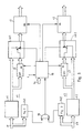
- a separate circuit branch is now provided for each of the two color difference signals yr, yb, which have the same structure with respect to one another, the circuit branch z1 being assigned to the red color difference channel and the circuit branch z2 being assigned to the blue color difference channel.
- the red color difference signal yr is at the input of the first retarder v1 or the first digital slope detector fsl.
- the output of the first delay v1 is at the input of the first memory s1 and at one input of the first switch us1, while the output of the first memory s1 is connected to the other input of the first switch us1, the output of which is at the input of the first output register r1.
- the second circuit branch z2 to which the blue color difference signals yb are fed on the input side is constructed identically as far as the individual subcircuits and their connection to one another are concerned and contains the respective second digital slope detector fs2, delay device v2, memory s2, changeover switch us2 and output register r2.
- the respective output signal of the two edge steepness detectors fsl, fs2 is supplied from the first or second input of the OR gate og, the output of which is connected to the first input of the sequential control system.
- the clock signal f is fed to its second input and the digital signal hz is fed to its third input, with which the hold time corresponding to the duration of the system-related rise time of the color difference channels can be specified.
- the various outputs of the sequential control system ab are connected to the respective memory transfer input en of the first and second memory s1, s2 and of the first and second output register r1, r2 and to the respective switch control input of the two changeover switches usl, us2.
- the sequential control system controls the subcircuits just mentioned in such a way that in the corresponding memory s1 or s2 a red or
- Blue color difference signal value yrl or yb1 is read.
- This intermediate value of the holding time is preferably in the middle.
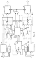
- FIG. 2 again shows in the form of a block diagram an embodiment of the arrangement according to FIG. 1.
- the development essentially consists in the fact that the first and second memories s1, s2 according to FIG. 1 are replaced by the third and fourth memories s3, s4 is supplemented, the signal flow is connected in parallel to the respective first-mentioned memory, and that the two change-over switches us1, us2 according to FIG. 1 are expanded to multiple change-over switches us1 ', us2' in such a way that in each case a further input with the output of the third or fourth memory s3, s4 is connected.
- the aforementioned designing part of FIG. 2 relates to the sequence control from FIG. 1.
- the counter c2 counting the clock signal f, the decoder dc and the AND gate us are provided for this.
- the start input st of the counter c2, with which the count is enabled, is connected to the output of the OR gate og, while the stop input sp is controlled by the decoder dc.
- This is also the digital signal hz, cf. Fig. 1, supplied.
- the decoding of the counter readings of the counter c2 takes place in such a way that the red or blue color difference signal value yr1 'or yb1' occurring at the end of the first third of the holding time is in the first or second memory s1, s2, but in the third or fourth memory s3, s4 the red or blue color difference signal value yr2 or yb2 occurring at the end of the second third of the holding time is read.
- the clock signal f is located at one input of the mentioned AND gate u2, while at the other input one of the outputs of the decoder dc is connected and its output is connected to the memory transfer input en of the first and second output registers r1, r2.
- FIG. 3 A preferred embodiment of the circuit for the edge steepness detectors fs1, fs2 is shown in FIG. 3 in the form of a block diagram. From the input for the color difference signal yr or yb, the first digital differentiator d1, the digital magnifier bb and the minuend input m of the first digital comparator k1 are connected in series in terms of signal flow. Its subtrahend input s is supplied with the digital signal ta corresponding to the amplitude threshold value.
- the magnitude generator bb gives at its output such digital values which are no longer signed with respect to their input value, and which therefore lack the sign bit, for example.
- B. in one or two's complement representation generates the corresponding positive digital number, for which purpose it contains a complement back converter in this case.
- a comparator is to be understood here as a digital circuit which compares the digital signals present at the two inputs to determine which of the two signals is larger than the other. Since this comparison of the arithmetic operation is purely formally closer to forming a difference than that of an addition, although the actual internal connection of such comparators is more similar to that of adders than that of subtractors, the two inputs are used for the sake of clarity as in the case of a subtractor with a minuend input or subtrahend input. Designated entrance. Three signals for “Minuend greater than Subtrahend”, “Subtrahend greater than Minuend” and “Minuend equal to Subtrahend” are suitable as logical output signals, and accordingly, as provided below, there are corresponding outputs with the names just mentioned.
- the enable input eb of the first counter c1, which counts the clock signal f, and the input of the second digital differentiator d2 are connected to the minuend-larger-subtrahend output ms of the first comparator k1.
- the counter status outputs of the first counter c1 are at the input of the fifth memory s5, the output of which is connected to the minuend input m of the second digital comparator k2.
- a digital signal tt corresponding to the time threshold value is supplied to its subtrahend input s.
- the reset input re of the first counter c1, the memory transfer input en of the fifth memory s5 and the first input of the first AND gate u1 are at the output of the second differentiating element d2.
- the subtrahend greater-minuend output sm of the second comparator k2 is connected to the second input of the second AND gate u2, the output of which leads to the OR gate according to FIG. 1 or 2.
- the subcircuits d1, bb, k1, d2 and, as already mentioned c1, are circuits operated on the clock signal f.
- FIG. 4a shows the assumed course of one of the two color difference signals yr or yb, it being noted that for the sake of clarity, the mode of presentation customary for analog signals has been chosen for the sake of clarity.
- FIG. 4b shows the output signal of the absolute value generator b and the amplitude threshold value corresponding to the digital signal ta. The time threshold value corresponding to the digital signal tt is also shown.
- FIG. 4c finally shows the course of the presumed color difference signal corresponding to the course according to FIG. 4a, but distributed in terms of waste, as occurs at the output of the output register r1, r2 according to FIG. 1 or 2.
- the comparison of FIGS. 4a and c shows that the last flank drawn on the right in these two figures is distributed. Since during this flank both the amplitude threshold value and the time threshold value are undershot (cf. the use of the subtrahend greater-minuend output sm of the second comparator k2), the steepening function becomes effective.
- the first comparator k1 emits a signal at the minuend-greater-subtrahend output ms as long as the output signal of the absolute value generator bb is greater than the amplitude threshold.
- the first counter c1 can count the clock signals until it is reset by a signal formed by means of the second differentiating element d2 from the trailing edge of the output signal of the first comparator kl.
- the counter reading of the counter c1 that was reached shortly before is transferred to the fifth memory s5 and compared with the time threshold value by means of the second comparator k2. If this is greater than the time period measured by means of the counter c1, the function already mentioned above runs.
- 5 serves to explain the formation of the distributed flank.
- 5a shows the flat course of an edge used for explanation.
- the distance between the points drawn into the curve in FIGS. 5a and b is intended to illustrate the period of the clock signal f.
- 5c shows the curve at the respective memory transfer input en of the output registers r1, r2.
- the signal which was periodically present at these inputs in time with the clock signal f is stopped, so to speak, so that no signals are transferred into the output registers r1, r2 over several clock periods, but rather at the end of the “Clocking” of the memory transfer input and the read signal remains in these registers.
- the signal values yr1 ', ybl' or yr2, yb2 read into the memories sl, s2 or s3, s4 at the end of the first third and the second third of the slowly rising flank of FIG. 5a are after the "timing" of the respective Memory input of the output registers r1, r2 at the beginning of the edge to be distributed, at the end of the first or second third of this edge to be distributed into the output registers r1, r2.
- the arrow drawn on the far right between FIGS. 5a and 5b is intended to illustrate that at the end of the flat edge of FIG. 5a the distributed edge according to FIG. 5b has reached the corresponding signal value.
- the time period for which the "timing" of the memory transfer inputs en of the output registers r1, r2 is "interrupted” according to FIG. 5c corresponds to the digital signal hz fed to the sequence control from FIG. 1 or the decoder dc according to FIG.
- circuit arrangement according to the invention can be easily implemented in a monolithically integrated form, wherein, since only digital circuits are used, the integration by means of insulating layer field-effect transistors, that is to say the use of so-called MOS technology, is particularly advantageous.
Landscapes
- Engineering & Computer Science (AREA)
- Multimedia (AREA)
- Signal Processing (AREA)
- Processing Of Color Television Signals (AREA)
Claims (3)
Priority Applications (5)
| Application Number | Priority Date | Filing Date | Title |
|---|---|---|---|
| DE8585104771T DE3571370D1 (en) | 1985-04-19 | 1985-04-19 | Steepening circuit for colour signal transients |
| EP85104771A EP0198103B1 (fr) | 1985-04-19 | 1985-04-19 | Circuit pour augmenter la pente des phénomènes transitoires de signaux couleur |
| CN86101799.4A CN1008873B (zh) | 1985-04-19 | 1986-03-20 | 彩色信号阶跃增陡电路 |
| US06/853,479 US4729014A (en) | 1985-04-19 | 1986-04-18 | Digital circuit for steepening color-signal transitions |
| JP61089850A JPS61244186A (ja) | 1985-04-19 | 1986-04-18 | カラー信号変化部の縁部を急峻にする回路装置 |
Applications Claiming Priority (1)
| Application Number | Priority Date | Filing Date | Title |
|---|---|---|---|
| EP85104771A EP0198103B1 (fr) | 1985-04-19 | 1985-04-19 | Circuit pour augmenter la pente des phénomènes transitoires de signaux couleur |
Publications (2)
| Publication Number | Publication Date |
|---|---|
| EP0198103A1 EP0198103A1 (fr) | 1986-10-22 |
| EP0198103B1 true EP0198103B1 (fr) | 1989-07-05 |
Family
ID=8193458
Family Applications (1)
| Application Number | Title | Priority Date | Filing Date |
|---|---|---|---|
| EP85104771A Expired EP0198103B1 (fr) | 1985-04-19 | 1985-04-19 | Circuit pour augmenter la pente des phénomènes transitoires de signaux couleur |
Country Status (5)
| Country | Link |
|---|---|
| US (1) | US4729014A (fr) |
| EP (1) | EP0198103B1 (fr) |
| JP (1) | JPS61244186A (fr) |
| CN (1) | CN1008873B (fr) |
| DE (1) | DE3571370D1 (fr) |
Families Citing this family (15)
| Publication number | Priority date | Publication date | Assignee | Title |
|---|---|---|---|---|
| JPS6439185A (en) * | 1987-08-04 | 1989-02-09 | Victor Company Of Japan | Enhancing circuit |
| JPH0822072B2 (ja) * | 1987-09-04 | 1996-03-04 | 日本ビクター株式会社 | 搬送色信号処理回路 |
| JP2503614B2 (ja) * | 1988-12-28 | 1996-06-05 | 三菱電機株式会社 | 映像信号輪郭補正装置 |
| US4935806A (en) * | 1988-12-30 | 1990-06-19 | Zenith Electronics Corporation | Chroma noise reduction and transient improvement |
| DE4009730A1 (de) * | 1990-03-27 | 1991-10-02 | Philips Patentverwaltung | Schaltungsanordnung zur versteilerung von signalflanken |
| ATE128309T1 (de) * | 1990-05-21 | 1995-10-15 | Siemens Ag | Verfahren zur farbkantenverbesserung bei der darstellung von farbfernsehbildern und fernsehgerät zur durchführung des verfahrens. |
| KR930011971B1 (ko) * | 1991-01-29 | 1993-12-23 | 삼성전자 주식회사 | 색신호 경계면 보정장치 |
| KR940006623B1 (ko) * | 1991-02-01 | 1994-07-23 | 삼성전자 주식회사 | 영상신호 처리 시스템 |
| JP3151624B2 (ja) * | 1991-02-25 | 2001-04-03 | アライド・シグナル・インコーポレーテツド | デイジタルビデオ量子器 |
| JP2719470B2 (ja) * | 1991-11-19 | 1998-02-25 | 三洋電機株式会社 | 色輪郭補正回路 |
| US5369446A (en) * | 1992-04-30 | 1994-11-29 | Thomson Consumer Electronics, Inc. | Video signal processor employing edge replacement, preshoots and overshoots for transient enhancement |
| US5374964A (en) * | 1993-08-04 | 1994-12-20 | Matsushita Electric Corporation Of America | Circuit and method for controlling abnormally slow transitions in color television signals |
| KR0130814B1 (en) * | 1993-12-18 | 1998-04-11 | Samsung Electronics Co Ltd | A contour correction method and apparatus of video signal |
| DE19639572A1 (de) * | 1996-09-26 | 1998-04-02 | Philips Patentverwaltung | Verfahren und Anordnung zur Farbkantenversteilerung |
| US6657677B1 (en) * | 2000-01-12 | 2003-12-02 | Koninklijke Philips Electronics N.V. | Method and apparatus for improving conversion from SD to HDTV |
Family Cites Families (5)
| Publication number | Priority date | Publication date | Assignee | Title |
|---|---|---|---|---|
| DE1562170B1 (de) * | 1968-03-19 | 1970-08-27 | Fernseh Gmbh | System zur Erhoehung der Schaerfe von Farbuebergaengen in Farbfernsehbildern |
| CH642211A5 (de) * | 1979-03-08 | 1984-03-30 | Siemens Ag Albis | Korrekturschaltung zur verbesserung der konturenschaerfe von fernsehbildern. |
| US4414564A (en) * | 1981-12-28 | 1983-11-08 | Magnavox Consumer Electronics Company | Nonlinear edge peaking system and method |
| DE3223580A1 (de) * | 1982-06-24 | 1983-12-29 | Philips Patentverwaltung Gmbh, 2000 Hamburg | Schaltungsanordnung zum erhoehen der schaerfe von farbkanten |
| US4542475A (en) * | 1982-11-23 | 1985-09-17 | Rca Corporation | Sampled data filter system as for a digital TV |
-
1985
- 1985-04-19 EP EP85104771A patent/EP0198103B1/fr not_active Expired
- 1985-04-19 DE DE8585104771T patent/DE3571370D1/de not_active Expired
-
1986
- 1986-03-20 CN CN86101799.4A patent/CN1008873B/zh not_active Expired
- 1986-04-18 JP JP61089850A patent/JPS61244186A/ja active Pending
- 1986-04-18 US US06/853,479 patent/US4729014A/en not_active Expired - Fee Related
Also Published As
| Publication number | Publication date |
|---|---|
| DE3571370D1 (en) | 1989-08-10 |
| CN1008873B (zh) | 1990-07-18 |
| US4729014A (en) | 1988-03-01 |
| JPS61244186A (ja) | 1986-10-30 |
| CN86101799A (zh) | 1986-10-15 |
| EP0198103A1 (fr) | 1986-10-22 |
Similar Documents
| Publication | Publication Date | Title |
|---|---|---|
| EP0198103B1 (fr) | Circuit pour augmenter la pente des phénomènes transitoires de signaux couleur | |
| EP0224302B1 (fr) | Circuit d'augmentation de la netteté de bords colorés | |
| DE2856551C3 (de) | Farbfernsehempfänger | |
| DE2115958C3 (de) | Variable Verzögerungsanordnung zur Einstellung der Phasenbeziehung zwischen zwei Signalen | |
| DE2628737A1 (de) | Fernsehempfaenger mit einer einrichtung zur gleichzeitigen wiedergabe mehrerer programme | |
| DE3207028C2 (de) | Anordnung zur Verbesserung des Kontrastes eines quantisierten impulsförmigen Videosignals | |
| EP0333273A2 (fr) | Générateur de signal de commande pour le traitement d'un signal vidéo | |
| DE1912866B2 (de) | Schaltungsanordnung zur Trennung eines Farbbildsignalgemisches in seine Färb und Videosignalkomponenten | |
| DE69106400T2 (de) | Automatisches Verfahren zur Farbfernsehnormidentifizierung. | |
| DE2652935A1 (de) | Verfahren und anordnung zur bildfrequenzwandlung | |
| EP0105998A1 (fr) | Circuit intégré d'un filtre numérique pour le canal de luminance d'appareils de télévision en couleurs | |
| CH641618A5 (de) | Wiedergabegeraet fuer ein auf einem aufzeichnungstraeger aufgezeichnetes farbfernsehsignal. | |
| DE3402230C2 (fr) | ||
| EP0111704B1 (fr) | Enregistreur vidéo avec enregistrement d'une porteuse de son | |
| DE69323550T2 (de) | Videospeicher | |
| DE2435265C2 (de) | System zur digitalen Übertragung von Farbfernsehsignalen | |
| EP0457931B1 (fr) | Procédé d'amélioration de bords colorés par visualisation d'images de télévision en couleur et récepteur de télévision pour sa mise en oeuvre | |
| DE2616593A1 (de) | System zur umschaltung zwischen zwei farbfernsehsignalen | |
| DE2364629A1 (de) | System zur codierung von video-signalen nach dem sogenannten differenzsignalverfahren | |
| DE2658449A1 (de) | Fernsehempfaenger mit einer einrichtung zur darstellung eines bildausschnitts als ausschnittsvergroesserung | |
| EP0307512A1 (fr) | Circuit découpeur de données numériques pour des signaux de télétexte | |
| DE3878019T2 (de) | Vorrichtung zur verarbeitung eines pal-videosignals. | |
| DE3139612C2 (de) | Transkodierschaltung | |
| DE2241485C3 (de) | Steuerschaltung für einen PAL-Farbfernsehdecoder | |
| DE3107567A1 (de) | Signalabtast-torschaltung |
Legal Events
| Date | Code | Title | Description |
|---|---|---|---|
| PUAI | Public reference made under article 153(3) epc to a published international application that has entered the european phase |
Free format text: ORIGINAL CODE: 0009012 |
|
| 17P | Request for examination filed |
Effective date: 19860416 |
|
| AK | Designated contracting states |
Kind code of ref document: A1 Designated state(s): DE FR GB IT NL |
|
| 17Q | First examination report despatched |
Effective date: 19881020 |
|
| GRAA | (expected) grant |
Free format text: ORIGINAL CODE: 0009210 |
|
| AK | Designated contracting states |
Kind code of ref document: B1 Designated state(s): DE FR GB IT NL |
|
| REF | Corresponds to: |
Ref document number: 3571370 Country of ref document: DE Date of ref document: 19890810 |
|
| GBT | Gb: translation of ep patent filed (gb section 77(6)(a)/1977) | ||
| ET | Fr: translation filed | ||
| ITF | It: translation for a ep patent filed | ||
| PLBE | No opposition filed within time limit |
Free format text: ORIGINAL CODE: 0009261 |
|
| STAA | Information on the status of an ep patent application or granted ep patent |
Free format text: STATUS: NO OPPOSITION FILED WITHIN TIME LIMIT |
|
| 26N | No opposition filed | ||
| ITTA | It: last paid annual fee | ||
| REG | Reference to a national code |
Ref country code: FR Ref legal event code: DL |
|
| PGFP | Annual fee paid to national office [announced via postgrant information from national office to epo] |
Ref country code: FR Payment date: 19950313 Year of fee payment: 11 |
|
| PGFP | Annual fee paid to national office [announced via postgrant information from national office to epo] |
Ref country code: GB Payment date: 19950327 Year of fee payment: 11 |
|
| PGFP | Annual fee paid to national office [announced via postgrant information from national office to epo] |
Ref country code: DE Payment date: 19950421 Year of fee payment: 11 |
|
| PGFP | Annual fee paid to national office [announced via postgrant information from national office to epo] |
Ref country code: NL Payment date: 19950430 Year of fee payment: 11 |
|
| PG25 | Lapsed in a contracting state [announced via postgrant information from national office to epo] |
Ref country code: GB Effective date: 19960419 |
|
| PG25 | Lapsed in a contracting state [announced via postgrant information from national office to epo] |
Ref country code: NL Effective date: 19961101 |
|
| GBPC | Gb: european patent ceased through non-payment of renewal fee |
Effective date: 19960419 |
|
| PG25 | Lapsed in a contracting state [announced via postgrant information from national office to epo] |
Ref country code: FR Effective date: 19961227 |
|
| PG25 | Lapsed in a contracting state [announced via postgrant information from national office to epo] |
Ref country code: DE Effective date: 19970101 |
|
| NLV4 | Nl: lapsed or anulled due to non-payment of the annual fee |
Effective date: 19961101 |
|
| REG | Reference to a national code |
Ref country code: FR Ref legal event code: ST |