EP0198103B1 - Steepening circuit for colour signal transients - Google Patents
Steepening circuit for colour signal transients Download PDFInfo
- Publication number
- EP0198103B1 EP0198103B1 EP85104771A EP85104771A EP0198103B1 EP 0198103 B1 EP0198103 B1 EP 0198103B1 EP 85104771 A EP85104771 A EP 85104771A EP 85104771 A EP85104771 A EP 85104771A EP 0198103 B1 EP0198103 B1 EP 0198103B1
- Authority
- EP
- European Patent Office
- Prior art keywords
- input
- output
- digital
- signal
- color
- Prior art date
- Legal status (The legal status is an assumption and is not a legal conclusion. Google has not performed a legal analysis and makes no representation as to the accuracy of the status listed.)
- Expired
Links
- 230000015654 memory Effects 0.000 claims description 41
- 238000010586 diagram Methods 0.000 description 6
- 230000000630 rising effect Effects 0.000 description 5
- 230000007704 transition Effects 0.000 description 4
- 230000006870 function Effects 0.000 description 3
- 230000000295 complement effect Effects 0.000 description 2
- 230000005540 biological transmission Effects 0.000 description 1
- 230000015572 biosynthetic process Effects 0.000 description 1
- 230000005669 field effect Effects 0.000 description 1
- 230000010354 integration Effects 0.000 description 1
- 239000002699 waste material Substances 0.000 description 1
Images


Classifications
-
- H—ELECTRICITY
- H04—ELECTRIC COMMUNICATION TECHNIQUE
- H04N—PICTORIAL COMMUNICATION, e.g. TELEVISION
- H04N9/00—Details of colour television systems
- H04N9/64—Circuits for processing colour signals
- H04N9/646—Circuits for processing colour signals for image enhancement, e.g. vertical detail restoration, cross-colour elimination, contour correction, chrominance trapping filters
Definitions
- the invention relates to a circuit arrangement for steepening color signal jumps in color television receivers with an edge steepness detector which emits a switching signal when a predeterminable amplitude threshold value is exceeded, by means of which a replacement signal is applied to the respective output of the two color difference channels for the duration of their system-related rise time, cf. the preamble of claim 1.
- p. 1-13 Stepping up of color signal jumps and luminance signal delay with the TDA 4560 circuit».
- the bandwidth of the color difference channel which is greatly reduced in comparison to the bandwidth of the luminance channel and which is only about 1/5 of that of the luminance channel in the television standards common today, leads to color signal jumps, for example at the edges of the usual test color bar signal, the color transitions are blurred and out of focus, since the small transmission bandwidth results in an approximately 5 times as long duration of the color signal transition as compared to the assigned luminance signal transition.
- the relatively flat color signal transitions at the edges are increased, which is essentially achieved by a corresponding delay in the color difference and luminance signals in conjunction with a distributed edge in the color difference signals at the end of the delay by corresponding analog circuits, since the color difference signals and the luminance signal are like Usually available and processed in analog form.
- the invention characterized in the claims is based on the object of modifying the principle described above in analog circuits so that it can be used in color television receivers known per se with digital signal processing (cf. “Electronics”, August 11, 1981, pages 97 to 103) , wherein the edge steepness detector should respond not only to one criterion, namely the predeterminable amplitude threshold value according to the arrangement described above, but to a further criterion.
- the digital color difference signals yr, yb are in the baseband at the frequency of the clock signal f, which has four times the color subcarrier frequency, i.e. the individual data words follow one another at this frequency. If a subharmonic of the clock signal f, for example the color subcarrier frequency itself, is selected for the color difference signal demodulation, as can be the case with known digital color television receivers, these digital signals are to be brought to the aforementioned signal repetition frequency of the clock signal f by digital interpolation.
- a separate circuit branch is now provided for each of the two color difference signals yr, yb, which have the same structure with respect to one another, the circuit branch z1 being assigned to the red color difference channel and the circuit branch z2 being assigned to the blue color difference channel.
- the red color difference signal yr is at the input of the first retarder v1 or the first digital slope detector fsl.
- the output of the first delay v1 is at the input of the first memory s1 and at one input of the first switch us1, while the output of the first memory s1 is connected to the other input of the first switch us1, the output of which is at the input of the first output register r1.
- the second circuit branch z2 to which the blue color difference signals yb are fed on the input side is constructed identically as far as the individual subcircuits and their connection to one another are concerned and contains the respective second digital slope detector fs2, delay device v2, memory s2, changeover switch us2 and output register r2.
- the respective output signal of the two edge steepness detectors fsl, fs2 is supplied from the first or second input of the OR gate og, the output of which is connected to the first input of the sequential control system.
- the clock signal f is fed to its second input and the digital signal hz is fed to its third input, with which the hold time corresponding to the duration of the system-related rise time of the color difference channels can be specified.
- the various outputs of the sequential control system ab are connected to the respective memory transfer input en of the first and second memory s1, s2 and of the first and second output register r1, r2 and to the respective switch control input of the two changeover switches usl, us2.
- the sequential control system controls the subcircuits just mentioned in such a way that in the corresponding memory s1 or s2 a red or
- Blue color difference signal value yrl or yb1 is read.
- This intermediate value of the holding time is preferably in the middle.
- FIG. 2 again shows in the form of a block diagram an embodiment of the arrangement according to FIG. 1.
- the development essentially consists in the fact that the first and second memories s1, s2 according to FIG. 1 are replaced by the third and fourth memories s3, s4 is supplemented, the signal flow is connected in parallel to the respective first-mentioned memory, and that the two change-over switches us1, us2 according to FIG. 1 are expanded to multiple change-over switches us1 ', us2' in such a way that in each case a further input with the output of the third or fourth memory s3, s4 is connected.
- the aforementioned designing part of FIG. 2 relates to the sequence control from FIG. 1.
- the counter c2 counting the clock signal f, the decoder dc and the AND gate us are provided for this.
- the start input st of the counter c2, with which the count is enabled, is connected to the output of the OR gate og, while the stop input sp is controlled by the decoder dc.
- This is also the digital signal hz, cf. Fig. 1, supplied.
- the decoding of the counter readings of the counter c2 takes place in such a way that the red or blue color difference signal value yr1 'or yb1' occurring at the end of the first third of the holding time is in the first or second memory s1, s2, but in the third or fourth memory s3, s4 the red or blue color difference signal value yr2 or yb2 occurring at the end of the second third of the holding time is read.
- the clock signal f is located at one input of the mentioned AND gate u2, while at the other input one of the outputs of the decoder dc is connected and its output is connected to the memory transfer input en of the first and second output registers r1, r2.
- FIG. 3 A preferred embodiment of the circuit for the edge steepness detectors fs1, fs2 is shown in FIG. 3 in the form of a block diagram. From the input for the color difference signal yr or yb, the first digital differentiator d1, the digital magnifier bb and the minuend input m of the first digital comparator k1 are connected in series in terms of signal flow. Its subtrahend input s is supplied with the digital signal ta corresponding to the amplitude threshold value.
- the magnitude generator bb gives at its output such digital values which are no longer signed with respect to their input value, and which therefore lack the sign bit, for example.
- B. in one or two's complement representation generates the corresponding positive digital number, for which purpose it contains a complement back converter in this case.
- a comparator is to be understood here as a digital circuit which compares the digital signals present at the two inputs to determine which of the two signals is larger than the other. Since this comparison of the arithmetic operation is purely formally closer to forming a difference than that of an addition, although the actual internal connection of such comparators is more similar to that of adders than that of subtractors, the two inputs are used for the sake of clarity as in the case of a subtractor with a minuend input or subtrahend input. Designated entrance. Three signals for “Minuend greater than Subtrahend”, “Subtrahend greater than Minuend” and “Minuend equal to Subtrahend” are suitable as logical output signals, and accordingly, as provided below, there are corresponding outputs with the names just mentioned.
- the enable input eb of the first counter c1, which counts the clock signal f, and the input of the second digital differentiator d2 are connected to the minuend-larger-subtrahend output ms of the first comparator k1.
- the counter status outputs of the first counter c1 are at the input of the fifth memory s5, the output of which is connected to the minuend input m of the second digital comparator k2.
- a digital signal tt corresponding to the time threshold value is supplied to its subtrahend input s.
- the reset input re of the first counter c1, the memory transfer input en of the fifth memory s5 and the first input of the first AND gate u1 are at the output of the second differentiating element d2.
- the subtrahend greater-minuend output sm of the second comparator k2 is connected to the second input of the second AND gate u2, the output of which leads to the OR gate according to FIG. 1 or 2.
- the subcircuits d1, bb, k1, d2 and, as already mentioned c1, are circuits operated on the clock signal f.
- FIG. 4a shows the assumed course of one of the two color difference signals yr or yb, it being noted that for the sake of clarity, the mode of presentation customary for analog signals has been chosen for the sake of clarity.
- FIG. 4b shows the output signal of the absolute value generator b and the amplitude threshold value corresponding to the digital signal ta. The time threshold value corresponding to the digital signal tt is also shown.
- FIG. 4c finally shows the course of the presumed color difference signal corresponding to the course according to FIG. 4a, but distributed in terms of waste, as occurs at the output of the output register r1, r2 according to FIG. 1 or 2.
- the comparison of FIGS. 4a and c shows that the last flank drawn on the right in these two figures is distributed. Since during this flank both the amplitude threshold value and the time threshold value are undershot (cf. the use of the subtrahend greater-minuend output sm of the second comparator k2), the steepening function becomes effective.
- the first comparator k1 emits a signal at the minuend-greater-subtrahend output ms as long as the output signal of the absolute value generator bb is greater than the amplitude threshold.
- the first counter c1 can count the clock signals until it is reset by a signal formed by means of the second differentiating element d2 from the trailing edge of the output signal of the first comparator kl.
- the counter reading of the counter c1 that was reached shortly before is transferred to the fifth memory s5 and compared with the time threshold value by means of the second comparator k2. If this is greater than the time period measured by means of the counter c1, the function already mentioned above runs.
- 5 serves to explain the formation of the distributed flank.
- 5a shows the flat course of an edge used for explanation.
- the distance between the points drawn into the curve in FIGS. 5a and b is intended to illustrate the period of the clock signal f.
- 5c shows the curve at the respective memory transfer input en of the output registers r1, r2.
- the signal which was periodically present at these inputs in time with the clock signal f is stopped, so to speak, so that no signals are transferred into the output registers r1, r2 over several clock periods, but rather at the end of the “Clocking” of the memory transfer input and the read signal remains in these registers.
- the signal values yr1 ', ybl' or yr2, yb2 read into the memories sl, s2 or s3, s4 at the end of the first third and the second third of the slowly rising flank of FIG. 5a are after the "timing" of the respective Memory input of the output registers r1, r2 at the beginning of the edge to be distributed, at the end of the first or second third of this edge to be distributed into the output registers r1, r2.
- the arrow drawn on the far right between FIGS. 5a and 5b is intended to illustrate that at the end of the flat edge of FIG. 5a the distributed edge according to FIG. 5b has reached the corresponding signal value.
- the time period for which the "timing" of the memory transfer inputs en of the output registers r1, r2 is "interrupted” according to FIG. 5c corresponds to the digital signal hz fed to the sequence control from FIG. 1 or the decoder dc according to FIG.
- circuit arrangement according to the invention can be easily implemented in a monolithically integrated form, wherein, since only digital circuits are used, the integration by means of insulating layer field-effect transistors, that is to say the use of so-called MOS technology, is particularly advantageous.
Landscapes
- Engineering & Computer Science (AREA)
- Multimedia (AREA)
- Signal Processing (AREA)
- Processing Of Color Television Signals (AREA)
Description
Die Erfindung betrifft eine Schaltungsanordnung zur Versteilerung von Farbsignalsprüngen in Farbfernsehempfängern mit einem Flankensteilheitsdetektor, der bei Überschreiten eines vorgebbaren Amplituden-Schwellwerts ein Schaltsignal abgibt, durch das an den jeweiligen Ausgang der beiden Farbdifferenzkanäle für die Dauer von deren systembedingter Anstiegszeit ein Ersatzsignal gelegt wird, vgl. den Oberbegriff des Anspruchs 1. Eine derartige Schaltungsanordnung ist in der Veröffentlichung der Firma Valvo «Technische Information 840228 (= 28.02.1984) S. 1-13: Versteilerung von Farbsignalsprüngen und Leuchtdichtesignal-Verzögerung mit der Schaltung TDA 4560» beschrieben.The invention relates to a circuit arrangement for steepening color signal jumps in color television receivers with an edge steepness detector which emits a switching signal when a predeterminable amplitude threshold value is exceeded, by means of which a replacement signal is applied to the respective output of the two color difference channels for the duration of their system-related rise time, cf. the preamble of
Die im Vergleich zur Bandbreite des Leuchtdichtekanals stark verringerte Bandbreite des Farbdifferenzkanals, die bei den heute üblichen Fernsehnormen nur etwa 1/5 von der des Leuchtdichtekanals beträgt, führt dazu, daß bei Farbsignalsprüngen, also beispielsweise an den Kanten des üblichen Test-Farb-Balkensignals, die Farbübergänge verwaschen und unscharf sind, da aus der kleinen Übertragungsbandbreite eine etwa 5mal so lange Dauer des Farbsignalübergangs im Vergleich zum zugeordneten Leuchtdichtesignal-Übergang resultiert. Mit der vorbeschriebenen Schaltung werden die relativ flach verlaufenden Farbsignalübergänge an Kanten versteilert, was im wesentlichen durch entsprechende Verzögerung der Farbdifferenz- und des Leuchtdichtesignals in Verbindung mit einer versteilerten Flanke der Farbdifferenzsignale am Ende der Verzögerung durch entsprechende Analogschaltungen erfolgt, da die Farbdifferenzsignale und das Leuchtdichtesignal wie üblich in analoger Form vorliegen und verarbeitet werden.The bandwidth of the color difference channel, which is greatly reduced in comparison to the bandwidth of the luminance channel and which is only about 1/5 of that of the luminance channel in the television standards common today, leads to color signal jumps, for example at the edges of the usual test color bar signal, the color transitions are blurred and out of focus, since the small transmission bandwidth results in an approximately 5 times as long duration of the color signal transition as compared to the assigned luminance signal transition. With the circuit described above, the relatively flat color signal transitions at the edges are increased, which is essentially achieved by a corresponding delay in the color difference and luminance signals in conjunction with a distributed edge in the color difference signals at the end of the delay by corresponding analog circuits, since the color difference signals and the luminance signal are like Usually available and processed in analog form.
Demgegenüber liegt der in den Ansprüchen gekennzeichneten Erfindung die Aufgabe zugrunde, das bei Analogschaltungen vorbeschriebene Prinzip so zu modifizieren, daß es bei an sich bekannten Farbfernsehempfängern mit digitaler Signalverarbeitung (vgl. «Electronics», 11.August 1981, Seiten 97 bis 103) anwendbar ist, wobei der Flankensteilheitsdetektor nicht nur auf ein Kriterium, nämlich den vorgebbaren Amplituden-Schwellwert entsprechend der vorbeschriebenen Anordnung, sondern auf ein weiteres Kriterium ansprechen soll.In contrast, the invention characterized in the claims is based on the object of modifying the principle described above in analog circuits so that it can be used in color television receivers known per se with digital signal processing (cf. “Electronics”, August 11, 1981, pages 97 to 103) , wherein the edge steepness detector should respond not only to one criterion, namely the predeterminable amplitude threshold value according to the arrangement described above, but to a further criterion.
Über die in der Aufgabenlösung bereits liegenden Vorteile hinausgehende Vorteile ergeben sich aus der nun folgenden Beschreibung der Erfindung anhand der Figuren der Zeichnungen.
- Fig. 1 zeigt in Form eines Blockschaltbildes ein erstes Ausführungsbeispiel der Erfindung;
- Fig. 2 zeigt ebenfalls in Form eines Blockschaltbildes eine ausgestaltende Weiterbildung der Anordnung nach Fig. 1;
- Fig. 3 zeigt als Blockschaltbild eine Ausführungsform für die Flankensteilheitsdetektoren in den Fig. 1 und 2;
- Fig. 4 zeigt verschiedene Kurven zur Erläuterung der prinzipiellen Wirkungsweise der Erfindung, und
- Fig. 5 zeigt Kurven zur Erläuterung der Wirkungsweise der Weiterbildung nach Fig. 2.
- Fig. 1 shows in the form of a block diagram a first embodiment of the invention;
- FIG. 2 also shows in the form of a block diagram an embodiment of the arrangement according to FIG. 1;
- Fig. 3 shows a block diagram of an embodiment for the slope detector in Figs. 1 and 2;
- Fig. 4 shows various curves to explain the principle of operation of the invention, and
- FIG. 5 shows curves to explain the mode of operation of the development according to FIG. 2.
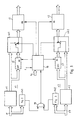
Beim Blockschaltbild der Fig. 1 liegen die digitalen Farbdifferenz-Signale yr, yb im Basisband mit der Frequenz des Taktsignals f, das die vierfache Farbhilfsträgerfrequenz hat, vor, d.h. die einzelnen Datenwörter folgen mit dieser Frequenz aufeinander. Falls für die Farbdifferenzsignal-Demodulation eine Subharmonische des Taktsignals f, also beispielsweise die Farbhilfsträgerfrequenz selbst, gewählt ist, wie dies bei bekannten digitalen Farbfernsehempfängern der Fall sein kann, so sind diese Digitalsignale durch digitale Interpolation auf die erwähnte Signalfolgefrequenz des Taktsignals f zu bringen.In the block diagram of Fig. 1, the digital color difference signals yr, yb are in the baseband at the frequency of the clock signal f, which has four times the color subcarrier frequency, i.e. the individual data words follow one another at this frequency. If a subharmonic of the clock signal f, for example the color subcarrier frequency itself, is selected for the color difference signal demodulation, as can be the case with known digital color television receivers, these digital signals are to be brought to the aforementioned signal repetition frequency of the clock signal f by digital interpolation.
In Fig. 1 ist nun für jedes der beiden Farbdifferenzsignale yr, yb ein eigener Schaltungszweig vorgesehen, die untereinander gleichen Aufbau haben, wobei dem Rot-Farbdifferenzkanal der Schaltungszweig z1 und dem Blau-Farbdifferenzkanal der Schaltungszweig z2 zugeordnet ist. Im Schaltungszweig z1 liegt das Rot-Farbdifferenzsignal yr am Eingang des ersten Verzögerers v1 bzw. des ersten digitalen Flankensteilheitsdetektors fsl. Der Ausgang des ersten Verzögerers v1 liegt am Eingang des ersten Speichers s1 und am einen Eingang des ersten Umschalters usl, wahrend der Ausgang des ersten Speichers s1 am anderen Eingang des ersten Umschalters us1 angeschlossen ist, dessen Ausgang am Eingang des ersten Ausgangsregisters r1 liegt.In Fig. 1, a separate circuit branch is now provided for each of the two color difference signals yr, yb, which have the same structure with respect to one another, the circuit branch z1 being assigned to the red color difference channel and the circuit branch z2 being assigned to the blue color difference channel. In the circuit branch z1, the red color difference signal yr is at the input of the first retarder v1 or the first digital slope detector fsl. The output of the first delay v1 is at the input of the first memory s1 and at one input of the first switch us1, while the output of the first memory s1 is connected to the other input of the first switch us1, the output of which is at the input of the first output register r1.
Der zweite Schaltungszweig z2, dem die Blau-Farbdifferenzsignale yb eingangsseitig zugeführt sind, ist, was die einzelnen Teilschaltungen und deren Verbindung untereinander betrifft, identisch aufgebaut und enthält den jeweils zweiten digitalen Flankensteilheitsdetektor fs2, Verzögerer v2, Speicher s2, Umschalter us2 und Ausgangsregister r2.The second circuit branch z2, to which the blue color difference signals yb are fed on the input side, is constructed identically as far as the individual subcircuits and their connection to one another are concerned and contains the respective second digital slope detector fs2, delay device v2, memory s2, changeover switch us2 and output register r2.
Das jeweilige Ausgangssignal der beiden Flankensteilheitsdetktoren fsl, fs2 ist vom ersten bzw. zweiten Eingang des ODER-Gatters og zugeführt, dessen Ausgang mit dem ersten Eingang der Ablaufsteuerung ab verbunden ist. Deren zweitem Eingang ist das Taktsignal f und deren drittem Eingang das Digitalsignal hz zugeführt, mit dem die der Dauer der systembedingten Anstiegszeit der Farbdifferenzkanäle entsprechende Haltezeit vorgegeben werden kann. Die verschiedenen Ausgänge der Ablaufsteuerung ab sind mit dem jeweiligen Speicherübernahme-Eingang en des ersten und zweiten Speichers s1, s2 sowie des ersten und zweiten Ausgangsregisters r1, r2 und mit dem jeweiligen Schalter-Steuereingang der beiden Umschalter usl, us2 verbunden.The respective output signal of the two edge steepness detectors fsl, fs2 is supplied from the first or second input of the OR gate og, the output of which is connected to the first input of the sequential control system. The clock signal f is fed to its second input and the digital signal hz is fed to its third input, with which the hold time corresponding to the duration of the system-related rise time of the color difference channels can be specified. The various outputs of the sequential control system ab are connected to the respective memory transfer input en of the first and second memory s1, s2 and of the first and second output register r1, r2 and to the respective switch control input of the two changeover switches usl, us2.
Die Ablaufsteuerung ab steuert die eben erwähnten Teilschaltungen derart, daß in den entsprechenden Speicher s1 bzw. s2 ein bei einem Zwischenwert der Haltezeit auftretender Rot- bzw.The sequential control system controls the subcircuits just mentioned in such a way that in the corresponding memory s1 or s2 a red or
Blau-Farbdifferenzsignal-Wert yrl bzw. yb1 eingelesen wird. Dieser Zwischenwert der Haltezeit liegt vorzugsweise in ihrer Mitte. Ferner bewirkt die Ablaufsteuerung, daß der Speicherinhalt des jeweiligen Speichers s1, s2 über den zugeordneten Umschalter us1 bzw. us2 beim entsprechenden Zwischenwert, vorzugsweise bei der Hälfte, der versteilerten Anstiegsflanke in das zugeordnete Ausgangsregister r1 bzw. r2 eingelesen wird, während dagegen zu allen anderen Zeiten als zum Zeitpunkt des Zwischenwerts der versteilerten Anstiegsflanke der Eingang des zugeordneten Ausgangsregisters zum Ausgang des entsprechenden Verzögerers v1 bzw. v2 durchgeschaltet ist.Blue color difference signal value yrl or yb1 is read. This intermediate value of the holding time is preferably in the middle. Furthermore, the Sequence control that the memory content of the respective memory s1, s2 is read in via the assigned changeover switch us1 or us2 at the corresponding intermediate value, preferably half, of the distributed rising edge in the assigned output register r1 or r2, while at other times than at Time of the intermediate value of the distributed rising edge of the input of the assigned output register to the output of the corresponding delay v1 or v2 is switched through.
Die Fig. 2 zeigt wiederum in Form eines Blockschaltbilds eine ausgestaltende Weiterbildung der Anordnung nach Fig. 1. Die Weiterbildung besteht im wesentlichen darin, daß der erste bzw. zweite Speicher s1, s2 nach Fig. 1 durch den dritten bzw. vierten Speicher s3, s4 ergänzt ist, der signalflußmäßig dem jeweils ersterwähnten Speicher parallelgeschaltet ist, und daß die beiden Umschalter us1, us2 nach Fig. 1 zu Mehrfachumschaltern us1', us2' derart erweitert sind, daß jeweils ein weiterer Eingang mit dem Ausgang des dritten bzw. vierten Speichers s3, s4 verbunden ist.FIG. 2 again shows in the form of a block diagram an embodiment of the arrangement according to FIG. 1. The development essentially consists in the fact that the first and second memories s1, s2 according to FIG. 1 are replaced by the third and fourth memories s3, s4 is supplemented, the signal flow is connected in parallel to the respective first-mentioned memory, and that the two change-over switches us1, us2 according to FIG. 1 are expanded to multiple change-over switches us1 ', us2' in such a way that in each case a further input with the output of the third or fourth memory s3, s4 is connected.
Der erwähnte ausgestaltende Teil der Fig. 2 betrifft die Ablaufsteuerung ab nach Fig. 1. In Fig. 2 sind hierfür der das Taktsignal f zählende Zähler c2, der Decoder dc sowie das UND-Gatter us vorgesehen. Der Starteingang st des Zählers c2, mit dem die Zählung freigegeben wird, ist mit dem Ausgang des ODER-Gatters og verbunden, während der Stopeingang sp vom Decoder dc angesteuert ist. Diesem ist auch das Digitalsignal hz, vgl. Fig. 1, zugeführt.The aforementioned designing part of FIG. 2 relates to the sequence control from FIG. 1. In FIG. 2, the counter c2 counting the clock signal f, the decoder dc and the AND gate us are provided for this. The start input st of the counter c2, with which the count is enabled, is connected to the output of the OR gate og, while the stop input sp is controlled by the decoder dc. This is also the digital signal hz, cf. Fig. 1, supplied.
Die Decodierung der Zählerstände des Zählers c2 erfolgt derart, daß in den ersten bzw. zweiten Speicher s1, s2 der am Ende des ersten Drittels der Haltezeit auftretende Rot- bzw. Blau-Farbdifferenzsignal-Wert yr1' bzw. yb1', dagegen in den dritten bzw. vierten Speicher s3, s4 der am Ende des zweiten Drittels der Haltezeit auftretende Rot- bzw. Blau-Farbdifferenzsignal-Wert yr2 bzw. yb2 eingelesen wird. Diese Speicherinhalte der vier Speicher s1...s4 gelangen über die beiden Umschalter us1', us2' am Ende des ersten bzw. zweiten Drittels der versteilerten Anstiegsflanke in das jeweilige Ausgangsregister r1, r2, und deren jeweiliger Eingang ist außer am Ende des ersten und des zweiten Drittels der versteilerten Anstiegsflanke zum Ausgang des ersten bzw. zweiten Verzögerers v1, v2 durchgeschaltet.The decoding of the counter readings of the counter c2 takes place in such a way that the red or blue color difference signal value yr1 'or yb1' occurring at the end of the first third of the holding time is in the first or second memory s1, s2, but in the third or fourth memory s3, s4 the red or blue color difference signal value yr2 or yb2 occurring at the end of the second third of the holding time is read. These memory contents of the four memories s1 ... s4 reach the respective output register r1, r2 via the two changeover switches us1 ', us2' at the end of the first or second third of the distributed rising edge, and their respective input is except at the end of the first and of the second third of the distributed rising edge to the output of the first and second retarders v1, v2.
Am einen Eingang des erwähnten UND-Gatters u2 liegt das Taktsignal f, während an dessen anderem Eingang einer der Ausgänge des Decoders dc angeschlossen ist und dessen Ausgang mit dem Speicherübernahme-Eingang en des ersten und zweiten Ausgangsregisters r1, r2 verbunden ist.The clock signal f is located at one input of the mentioned AND gate u2, while at the other input one of the outputs of the decoder dc is connected and its output is connected to the memory transfer input en of the first and second output registers r1, r2.
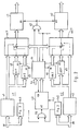
In Fig. 3 ist in Form eines Blockschaltbilds eine bevorzugte Ausführungsform der Schaltung für die Flankensteilheitsdetektoren fs1, fs2 gezeigt. Vom Eingang für das Farbdifferenzsignal yr bzw. yb aus liegen signaflußmäßig das erste digitale Differenzierglied d1, der digitale Betragsbildner bb und der Minuend-Eingang m des ersten digitalen Komparators k1 in Reihe. Dessen Subtrahend-Eingang s ist das dem Amplituden-Schwellwert entsprechende Digitalsignal ta zugeführt.A preferred embodiment of the circuit for the edge steepness detectors fs1, fs2 is shown in FIG. 3 in the form of a block diagram. From the input for the color difference signal yr or yb, the first digital differentiator d1, the digital magnifier bb and the minuend input m of the first digital comparator k1 are connected in series in terms of signal flow. Its subtrahend input s is supplied with the digital signal ta corresponding to the amplitude threshold value.
Der Betragsbildner bb gibt an seinem Ausgang jeweils solche Digitalwerte, die bezüglich ihres Eingangswerts nicht mehr vorzeichenbehaftet sind, denen also beispielsweise das Vorzeichenbit fehlt. Dies bedeutet schaltungstechnisch, daß der Betragsbildner bb einen Schaltungsteil enthält, der aus negativen Digitalzahlen z. B. in Einer- oder Zweier-Komplementdarstellung die entsprechende positive Digitalzahl erzeugt, wozu er in diesem Falle einen Komplement-Rückwandler enthält.The magnitude generator bb gives at its output such digital values which are no longer signed with respect to their input value, and which therefore lack the sign bit, for example. In terms of circuitry, this means that the amount generator bb contains a circuit part that consists of negative digital numbers such. B. in one or two's complement representation generates the corresponding positive digital number, for which purpose it contains a complement back converter in this case.
Unter einem Komparator soll hier eine Digitalschaltung verstanden werden, die einen Vergleich der an den beiden Eingängen anliegenden Digitalsignale dahingehend vornimmt, welches der beiden Signale größer als das andere ist. Da diese Vergleichsbildung der Rechenoperation einer Differenzbildung rein formal näher steht als der einer Addition, obwohl die konkrete Innenschaltung solcher Komparatoren denen von Addierern ähnlicher ist als denen von Subtrahierern, werden aus Eindeutigkeitsgründen die beiden Eingänge wie bei einem Subtrahierer mit Minuend-Eingang bzw. Subtrahend-Eingang bezeichnet. Als logische Ausgangssignale kommen drei Signale für «Minuend größer Subtrahend», «Subtrahend größer Minuend» und «Minuend gleich Subtrahend» als sinnvoll in Betracht, und dementsprechend sind, wie im folgenden vorgesehen ist, entsprechende Ausgänge mit den eben genannten Bezeichnungen vorhanden. Am Minuend-größer-Subtrahend-Ausgang eines Komparators tritt bei vorausgesetzter positiver Logik also der positivere zweier Binärpegel auf, wenn und solange der Minuend größer als der Subtrahend ist. Es ist selbstverständlich, daß im Bedarfsfall der an diesem Ausgang auftretende negativere der beiden Binärpegel dazu dienen kann, die Funktion «Minuend kleiner Subtrahend» zu signalisieren, was dann allerdings negativer Logik entsprechen würde.A comparator is to be understood here as a digital circuit which compares the digital signals present at the two inputs to determine which of the two signals is larger than the other. Since this comparison of the arithmetic operation is purely formally closer to forming a difference than that of an addition, although the actual internal connection of such comparators is more similar to that of adders than that of subtractors, the two inputs are used for the sake of clarity as in the case of a subtractor with a minuend input or subtrahend input. Designated entrance. Three signals for “Minuend greater than Subtrahend”, “Subtrahend greater than Minuend” and “Minuend equal to Subtrahend” are suitable as logical output signals, and accordingly, as provided below, there are corresponding outputs with the names just mentioned. With positive logic assuming positive logic, the more positive two binary levels occur at the minuend-larger-subtrahend output if and as long as the minuend is larger than the subtrahend. It goes without saying that, if necessary, the more negative of the two binary levels occurring at this output can serve to signal the "Minuend less subtrahend" function, which would then correspond to negative logic.
Beim Flankensteilheitsdetektor nach Fig. 3 sind ferner der Enable-Eingang eb des das Taktsignal f zählenden ersten Zählers c1 und der Eingang des zweiten digitalen Differenzierglieds d2 mit dem Minuend-größer-Subtrahend-Ausgang ms des ersten Komparators k1 verbunden. Die Zählerstandausgänge des ersten Zählers c1 liegen am Eingang des fünften Speichers s5, dessen Ausgang am Minuend-Eingang m des zweiten digitalen Komparators k2 angeschlossen ist. Dessen Subtrahend-Eingang s ist ein dem Zeitschwellwert entsprechendes Digitalsignal tt zugeführt.3, the enable input eb of the first counter c1, which counts the clock signal f, and the input of the second digital differentiator d2 are connected to the minuend-larger-subtrahend output ms of the first comparator k1. The counter status outputs of the first counter c1 are at the input of the fifth memory s5, the output of which is connected to the minuend input m of the second digital comparator k2. A digital signal tt corresponding to the time threshold value is supplied to its subtrahend input s.
Der Reset-Eingang re des ersten Zählers c1, der Speicherübernahmeeingang en des fünften Speichers s5 und der erste Eingang des ersten UND-Gatters u1 liegen am Ausgang des zweiten Differenzierglieds d2. Schließlich ist der Subtrahend-größer-Minuend-Ausgang sm des zweiten Komparators k2 mit dem zweiten Eingang des zweiten UND-Gatters u2 verbunden, dessen Ausgang zum ODER-Gatter nach Fig. 1 oder 2 führt. Die Teilschaltungen d1, bb, k1, d2 und, wie bereits erwähnt c1, sind am Taktsignal f betriebene Schaltungen.The reset input re of the first counter c1, the memory transfer input en of the fifth memory s5 and the first input of the first AND gate u1 are at the output of the second differentiating element d2. Finally, the subtrahend greater-minuend output sm of the second comparator k2 is connected to the second input of the second AND gate u2, the output of which leads to the OR gate according to FIG. 1 or 2. The subcircuits d1, bb, k1, d2 and, as already mentioned c1, are circuits operated on the clock signal f.
Zur Veranschaulichung der Wirkungsweise der erfindungsgemäßen Schaltungsanordnung sollen die Fig. 4 und 5 dienen. Fig. 4a zeigt den angenommenen Verlauf eines der beiden Farbdifferenzsignale yr, bzw. yb, wobei angemerkt sei, daß für die Darstellung in diesen Figuren aus Anschaulichkeitsgründen die für Analogsignale übliche Darstellungsweise gewählt ist.4 and 5 are intended to illustrate the mode of operation of the circuit arrangement according to the invention. FIG. 4a shows the assumed course of one of the two color difference signals yr or yb, it being noted that for the sake of clarity, the mode of presentation customary for analog signals has been chosen for the sake of clarity.
Die Fig. 4b zeigt das Ausgangssignal des Betragsbildners b sowie den dem Digitalsignal ta entsprechenden Amplitudenschwellwert. Ferner ist der dem Digitalsignal tt entsprechende Zeit- Schwellwert eingezeichnet. Die Fig. 4c zeigt schließlich den dem Verlauf nach Fig. 4a entsprechenden, jedoch abfallversteilerten Verlauf des vorausgesetzten Farbdifferenzsignals, wie es am Ausgang des Ausgangsregisters r1, r2 nach Fig. 1 oder 2 auftritt. Der Vergleich der Fig. 4a und c zeigt, daß die letzte, rechts in diesen beiden Figuren gezeichnete Flanke versteilert ist. Da während dieser Flanke sowohl der Amplitudenschwellwert überschritten als auch der Zeitschwellwert unterschritten ist (vgl. die Verwendung des Subtrahend-größer-Minuend-Ausgangs sm des zweiten Komparators k2), wird die Versteilerungsfunktion wirksam. Der erste Komparator k1 gibt nämlich am Minuend-größer-Subtrahend-Ausgang ms solange ein Signal ab, wie das Ausgangssignal des Betragsbildners bb größer als der Amplituden- schwellwert ist. Während dieser Zeit kann der erste Zähler c1 die Taktsignale zählen, bis er von einem mittels des zweiten Differenzierglieds d2 aus der Rückflanke des Ausgangssignals des ersten Komparators kl gebildeten Signal wieder zurückgesetzt wird. Der kurz zuvor erreichte Zählerstand des Zählers c1 wird in den fünften Speicher s5 übernommen und mittels des zweiten Komparators k2 mit dem Zeitschwellwert verglichen. Ist dieser größer als die mittels des Zählers c1 gemessene Zeitdauer, so läuft die oben bereits erwähnte Funktion ab.4b shows the output signal of the absolute value generator b and the amplitude threshold value corresponding to the digital signal ta. The time threshold value corresponding to the digital signal tt is also shown. FIG. 4c finally shows the course of the presumed color difference signal corresponding to the course according to FIG. 4a, but distributed in terms of waste, as occurs at the output of the output register r1, r2 according to FIG. 1 or 2. The comparison of FIGS. 4a and c shows that the last flank drawn on the right in these two figures is distributed. Since during this flank both the amplitude threshold value and the time threshold value are undershot (cf. the use of the subtrahend greater-minuend output sm of the second comparator k2), the steepening function becomes effective. The first comparator k1 emits a signal at the minuend-greater-subtrahend output ms as long as the output signal of the absolute value generator bb is greater than the amplitude threshold. During this time, the first counter c1 can count the clock signals until it is reset by a signal formed by means of the second differentiating element d2 from the trailing edge of the output signal of the first comparator kl. The counter reading of the counter c1 that was reached shortly before is transferred to the fifth memory s5 and compared with the time threshold value by means of the second comparator k2. If this is greater than the time period measured by means of the counter c1, the function already mentioned above runs.
Die Fig. 5 dient zur Erläuterung der Bildung der versteilerten Flanke. Fig. 5a zeigt dabei den flachen Verlauf einer zur Erläuterung herangezogenen Flanke. Der Abstand zwischen den in den Fig. 5a und b in den Kurvenverlauf eingezeichneten Punkte soll dabei die Periodendauer des Taktsignals f veranschaulichen. Die Fig. 5c zeigt den Kurvenverlauf am jeweiligen Speicherübernahmeeingang en der Ausgangsregister r1, r2. Beim zwischen den Fig. 5a und b links eingezeichneten Pfeil wird das zuvor an diesen Eingängen im Takt des Taktsignals f periodisch anliegende Signal sozusagen gestoppt, so daß über mehrere Taktperioden hinweg keine Signale in die Ausgangsregister r1, r2 übernommen werden, sondern das am Ende der «Taktung» des Speicherübernahmeeingangs en eingelesene Signal in diesen Registern stehenbleibt. Die am Ende des ersten Drittels und des zweiten Dritteis der langsam ansteigenden Flanke der Fig. 5a in die Speicher sl, s2 bzw. s3, s4 eingelesenen Signalwerte yr1', ybl' bzw. yr2, yb2 weraen, nachdem die «Taktung» des jeweiligen Speicnerübernahmeeingangs der Ausgangsregi- ster r1, r2 zu Beginn der zu versteilernden Flanke wieder eingesetzt hat, am Ende des ersten bzw. zweiten Drittels dieser zu versteilernden Flanke in die Ausgangsregister r1, r2 übernommen. Der ganz rechts zwischen den Fig. 5a und 5b eigezeichnete Pfeil soll veranschaulichen, daß am Ende der flachen Flanke von Fig. 5a die versteilerte Flanke nach Fig. 5b den entsprechenden Signalwert erreicht hat.5 serves to explain the formation of the distributed flank. 5a shows the flat course of an edge used for explanation. The distance between the points drawn into the curve in FIGS. 5a and b is intended to illustrate the period of the clock signal f. 5c shows the curve at the respective memory transfer input en of the output registers r1, r2. In the arrow drawn in between FIGS. 5a and b, the signal which was periodically present at these inputs in time with the clock signal f is stopped, so to speak, so that no signals are transferred into the output registers r1, r2 over several clock periods, but rather at the end of the “Clocking” of the memory transfer input and the read signal remains in these registers. The signal values yr1 ', ybl' or yr2, yb2 read into the memories sl, s2 or s3, s4 at the end of the first third and the second third of the slowly rising flank of FIG. 5a are after the "timing" of the respective Memory input of the output registers r1, r2 at the beginning of the edge to be distributed, at the end of the first or second third of this edge to be distributed into the output registers r1, r2. The arrow drawn on the far right between FIGS. 5a and 5b is intended to illustrate that at the end of the flat edge of FIG. 5a the distributed edge according to FIG. 5b has reached the corresponding signal value.
Die Zeitdauer, für die nach Fig. 5c die «Taktung» der Speicherübernahmeeingänge en der Ausgangsregister r1, r2 «unterbrochen» ist, entspricht dem der Ablaufsteuerung ab nach Fig. 1 bzw. dem Decoder dc nach Fig. 2 zugeführten Digitalsignal hz.The time period for which the "timing" of the memory transfer inputs en of the output registers r1, r2 is "interrupted" according to FIG. 5c corresponds to the digital signal hz fed to the sequence control from FIG. 1 or the decoder dc according to FIG.
Die erfindungsgemäße Schaltungsanordnung läßt sich ohne weiteres in monolithisch integrierter Form realisieren, wobei, da auschließlich Digitalschaltungen benutzt werden, die Integrierung mittels Isolierschicht-Feldeffekt-Transistoren, also die Anwendung der sogenannten MOS-Technik besonders vorteilhaft ist.The circuit arrangement according to the invention can be easily implemented in a monolithically integrated form, wherein, since only digital circuits are used, the integration by means of insulating layer field-effect transistors, that is to say the use of so-called MOS technology, is particularly advantageous.
Claims (3)
Priority Applications (5)
| Application Number | Priority Date | Filing Date | Title |
|---|---|---|---|
| EP85104771A EP0198103B1 (en) | 1985-04-19 | 1985-04-19 | Steepening circuit for colour signal transients |
| DE8585104771T DE3571370D1 (en) | 1985-04-19 | 1985-04-19 | Steepening circuit for colour signal transients |
| CN86101799.4A CN1008873B (en) | 1985-04-19 | 1986-03-20 | Circuit arrangement for steepening color-signal transitions |
| JP61089850A JPS61244186A (en) | 1985-04-19 | 1986-04-18 | Circuit device for steeping rim of color signal changing section |
| US06/853,479 US4729014A (en) | 1985-04-19 | 1986-04-18 | Digital circuit for steepening color-signal transitions |
Applications Claiming Priority (1)
| Application Number | Priority Date | Filing Date | Title |
|---|---|---|---|
| EP85104771A EP0198103B1 (en) | 1985-04-19 | 1985-04-19 | Steepening circuit for colour signal transients |
Publications (2)
| Publication Number | Publication Date |
|---|---|
| EP0198103A1 EP0198103A1 (en) | 1986-10-22 |
| EP0198103B1 true EP0198103B1 (en) | 1989-07-05 |
Family
ID=8193458
Family Applications (1)
| Application Number | Title | Priority Date | Filing Date |
|---|---|---|---|
| EP85104771A Expired EP0198103B1 (en) | 1985-04-19 | 1985-04-19 | Steepening circuit for colour signal transients |
Country Status (5)
| Country | Link |
|---|---|
| US (1) | US4729014A (en) |
| EP (1) | EP0198103B1 (en) |
| JP (1) | JPS61244186A (en) |
| CN (1) | CN1008873B (en) |
| DE (1) | DE3571370D1 (en) |
Families Citing this family (15)
| Publication number | Priority date | Publication date | Assignee | Title |
|---|---|---|---|---|
| JPS6439185A (en) * | 1987-08-04 | 1989-02-09 | Victor Company Of Japan | Enhancing circuit |
| JPH0822072B2 (en) * | 1987-09-04 | 1996-03-04 | 日本ビクター株式会社 | Carrier color signal processing circuit |
| JP2503614B2 (en) * | 1988-12-28 | 1996-06-05 | 三菱電機株式会社 | Video signal contour correction device |
| US4935806A (en) * | 1988-12-30 | 1990-06-19 | Zenith Electronics Corporation | Chroma noise reduction and transient improvement |
| DE4009730A1 (en) * | 1990-03-27 | 1991-10-02 | Philips Patentverwaltung | CIRCUIT FOR THE AMPLIFICATION OF SIGNAL FLANKS |
| ATE128309T1 (en) * | 1990-05-21 | 1995-10-15 | Siemens Ag | METHOD FOR COLOR EDGE IMPROVEMENT IN THE DISPLAY OF COLOR TELEVISION IMAGES AND TELEVISION DEVICE FOR CARRYING OUT THE METHOD. |
| KR930011971B1 (en) * | 1991-01-29 | 1993-12-23 | 삼성전자 주식회사 | Color signal border sharpness compensation circuit |
| KR940006623B1 (en) * | 1991-02-01 | 1994-07-23 | 삼성전자 주식회사 | Image signal processing system |
| EP0573513B1 (en) * | 1991-02-25 | 1995-10-04 | AlliedSignal Inc. | Digital video quantizer |
| JP2719470B2 (en) * | 1991-11-19 | 1998-02-25 | 三洋電機株式会社 | Color contour correction circuit |
| US5369446A (en) * | 1992-04-30 | 1994-11-29 | Thomson Consumer Electronics, Inc. | Video signal processor employing edge replacement, preshoots and overshoots for transient enhancement |
| US5374964A (en) * | 1993-08-04 | 1994-12-20 | Matsushita Electric Corporation Of America | Circuit and method for controlling abnormally slow transitions in color television signals |
| KR0130814B1 (en) * | 1993-12-18 | 1998-04-11 | Samsung Electronics Co Ltd | A contour correction method and apparatus of video signal |
| DE19639572A1 (en) * | 1996-09-26 | 1998-04-02 | Philips Patentverwaltung | Process and arrangement for color edge distribution |
| US6657677B1 (en) | 2000-01-12 | 2003-12-02 | Koninklijke Philips Electronics N.V. | Method and apparatus for improving conversion from SD to HDTV |
Family Cites Families (5)
| Publication number | Priority date | Publication date | Assignee | Title |
|---|---|---|---|---|
| DE1562170B1 (en) * | 1968-03-19 | 1970-08-27 | Fernseh Gmbh | System for increasing the sharpness of color transitions in color television pictures |
| CH642211A5 (en) * | 1979-03-08 | 1984-03-30 | Siemens Ag Albis | CORRECTION CIRCUIT TO IMPROVE THE SHARPNESS OF TELEVISION PICTURES. |
| US4414564A (en) * | 1981-12-28 | 1983-11-08 | Magnavox Consumer Electronics Company | Nonlinear edge peaking system and method |
| DE3223580A1 (en) * | 1982-06-24 | 1983-12-29 | Philips Patentverwaltung Gmbh, 2000 Hamburg | CIRCUIT ARRANGEMENT FOR INCREASING THE SHARPNESS OF COLOR EDGES |
| US4542475A (en) * | 1982-11-23 | 1985-09-17 | Rca Corporation | Sampled data filter system as for a digital TV |
-
1985
- 1985-04-19 DE DE8585104771T patent/DE3571370D1/en not_active Expired
- 1985-04-19 EP EP85104771A patent/EP0198103B1/en not_active Expired
-
1986
- 1986-03-20 CN CN86101799.4A patent/CN1008873B/en not_active Expired
- 1986-04-18 US US06/853,479 patent/US4729014A/en not_active Expired - Fee Related
- 1986-04-18 JP JP61089850A patent/JPS61244186A/en active Pending
Also Published As
| Publication number | Publication date |
|---|---|
| CN86101799A (en) | 1986-10-15 |
| US4729014A (en) | 1988-03-01 |
| CN1008873B (en) | 1990-07-18 |
| JPS61244186A (en) | 1986-10-30 |
| EP0198103A1 (en) | 1986-10-22 |
| DE3571370D1 (en) | 1989-08-10 |
Similar Documents
| Publication | Publication Date | Title |
|---|---|---|
| EP0198103B1 (en) | Steepening circuit for colour signal transients | |
| EP0224302B1 (en) | Circuitry for increasing the sharpness of colour edges | |
| DE2856551C3 (en) | Color television receiver | |
| DE2115958C3 (en) | Variable delay arrangement for setting the phase relationship between two signals | |
| DE2628737A1 (en) | TELEVISION RECEIVER WITH A DEVICE FOR THE SIMULTANEOUS PLAYBACK OF MULTIPLE PROGRAMS | |
| DE3207028C2 (en) | Arrangement for improving the contrast of a quantized pulse-shaped video signal | |
| EP0333273A2 (en) | Control signal generator for processing a video signal | |
| DE1912866B2 (en) | Circuit arrangement for the separation of a color image signal mixture into its color and video signal components | |
| DE69106400T2 (en) | Automatic procedure for color television standard identification. | |
| DE2652935A1 (en) | METHOD AND ARRANGEMENT FOR IMAGE FREQUENCY CONVERSION | |
| EP0105998A1 (en) | Integrated digital filter circuit for the luminance channel of colour television sets | |
| CH641618A5 (en) | PLAYBACK FOR A COLOR TELEVISION SIGNAL RECORDED ON A RECORDING CARRIER. | |
| DE3402230C2 (en) | ||
| EP0111704B1 (en) | Video recorder capable of recording a sound carrier | |
| DE69323550T2 (en) | VIDEO STORAGE | |
| DE2435265C2 (en) | System for the digital transmission of color television signals | |
| EP0457931B1 (en) | Method to improve colour edges by displaying colour television pictures | |
| DE2616593A1 (en) | SYSTEM FOR SWITCHING BETWEEN TWO COLOR TV SIGNALS | |
| DE2364629A1 (en) | SYSTEM FOR CODING VIDEO SIGNALS ACCORDING TO THE SO-CALLED DIFFERENTIAL SIGNAL PROCEDURE | |
| DE2658449A1 (en) | TELEVISION RECEIVER WITH A DEVICE FOR THE DISPLAY OF A PICTURE SECTION AS A SECTION ENLARGEMENT | |
| EP0307512A1 (en) | Digital data slicing circuit for teletext signals | |
| DE3878019T2 (en) | DEVICE FOR PROCESSING A PAL VIDEO SIGNAL. | |
| DE3139612C2 (en) | Transcoding circuit | |
| DE2241485C3 (en) | Control circuit for a PAL color television decoder | |
| DE3107567A1 (en) | Signal sampling gate circuit |
Legal Events
| Date | Code | Title | Description |
|---|---|---|---|
| PUAI | Public reference made under article 153(3) epc to a published international application that has entered the european phase |
Free format text: ORIGINAL CODE: 0009012 |
|
| 17P | Request for examination filed |
Effective date: 19860416 |
|
| AK | Designated contracting states |
Kind code of ref document: A1 Designated state(s): DE FR GB IT NL |
|
| 17Q | First examination report despatched |
Effective date: 19881020 |
|
| GRAA | (expected) grant |
Free format text: ORIGINAL CODE: 0009210 |
|
| AK | Designated contracting states |
Kind code of ref document: B1 Designated state(s): DE FR GB IT NL |
|
| REF | Corresponds to: |
Ref document number: 3571370 Country of ref document: DE Date of ref document: 19890810 |
|
| GBT | Gb: translation of ep patent filed (gb section 77(6)(a)/1977) | ||
| ET | Fr: translation filed | ||
| ITF | It: translation for a ep patent filed | ||
| PLBE | No opposition filed within time limit |
Free format text: ORIGINAL CODE: 0009261 |
|
| STAA | Information on the status of an ep patent application or granted ep patent |
Free format text: STATUS: NO OPPOSITION FILED WITHIN TIME LIMIT |
|
| 26N | No opposition filed | ||
| ITTA | It: last paid annual fee | ||
| REG | Reference to a national code |
Ref country code: FR Ref legal event code: DL |
|
| PGFP | Annual fee paid to national office [announced via postgrant information from national office to epo] |
Ref country code: FR Payment date: 19950313 Year of fee payment: 11 |
|
| PGFP | Annual fee paid to national office [announced via postgrant information from national office to epo] |
Ref country code: GB Payment date: 19950327 Year of fee payment: 11 |
|
| PGFP | Annual fee paid to national office [announced via postgrant information from national office to epo] |
Ref country code: DE Payment date: 19950421 Year of fee payment: 11 |
|
| PGFP | Annual fee paid to national office [announced via postgrant information from national office to epo] |
Ref country code: NL Payment date: 19950430 Year of fee payment: 11 |
|
| PG25 | Lapsed in a contracting state [announced via postgrant information from national office to epo] |
Ref country code: GB Effective date: 19960419 |
|
| PG25 | Lapsed in a contracting state [announced via postgrant information from national office to epo] |
Ref country code: NL Effective date: 19961101 |
|
| GBPC | Gb: european patent ceased through non-payment of renewal fee |
Effective date: 19960419 |
|
| PG25 | Lapsed in a contracting state [announced via postgrant information from national office to epo] |
Ref country code: FR Effective date: 19961227 |
|
| PG25 | Lapsed in a contracting state [announced via postgrant information from national office to epo] |
Ref country code: DE Effective date: 19970101 |
|
| NLV4 | Nl: lapsed or anulled due to non-payment of the annual fee |
Effective date: 19961101 |
|
| REG | Reference to a national code |
Ref country code: FR Ref legal event code: ST |