EP0197777B1 - Vorrichtung und Verfahren zum Brikettieren von faserigem Erntegut oder dergleichen - Google Patents
Vorrichtung und Verfahren zum Brikettieren von faserigem Erntegut oder dergleichen Download PDFInfo
- Publication number
- EP0197777B1 EP0197777B1 EP86302514A EP86302514A EP0197777B1 EP 0197777 B1 EP0197777 B1 EP 0197777B1 EP 86302514 A EP86302514 A EP 86302514A EP 86302514 A EP86302514 A EP 86302514A EP 0197777 B1 EP0197777 B1 EP 0197777B1
- Authority
- EP
- European Patent Office
- Prior art keywords
- crop
- compression
- roller
- protrusions
- column
- Prior art date
- Legal status (The legal status is an assumption and is not a legal conclusion. Google has not performed a legal analysis and makes no representation as to the accuracy of the status listed.)
- Expired
Links
Images


Classifications
-
- B—PERFORMING OPERATIONS; TRANSPORTING
- B30—PRESSES
- B30B—PRESSES IN GENERAL
- B30B15/00—Details of, or accessories for, presses; Auxiliary measures in connection with pressing
- B30B15/06—Platens or press rams
- B30B15/065—Press rams
-
- B—PERFORMING OPERATIONS; TRANSPORTING
- B30—PRESSES
- B30B—PRESSES IN GENERAL
- B30B11/00—Presses specially adapted for forming shaped articles from material in particulate or plastic state, e.g. briquetting presses, tabletting presses
- B30B11/02—Presses specially adapted for forming shaped articles from material in particulate or plastic state, e.g. briquetting presses, tabletting presses using a ram exerting pressure on the material in a moulding space
- B30B11/027—Particular press methods or systems
-
- B—PERFORMING OPERATIONS; TRANSPORTING
- B30—PRESSES
- B30B—PRESSES IN GENERAL
- B30B11/00—Presses specially adapted for forming shaped articles from material in particulate or plastic state, e.g. briquetting presses, tabletting presses
- B30B11/16—Presses specially adapted for forming shaped articles from material in particulate or plastic state, e.g. briquetting presses, tabletting presses using pocketed rollers, e.g. two co-operating pocketed rollers
-
- B—PERFORMING OPERATIONS; TRANSPORTING
- B30—PRESSES
- B30B—PRESSES IN GENERAL
- B30B11/00—Presses specially adapted for forming shaped articles from material in particulate or plastic state, e.g. briquetting presses, tabletting presses
- B30B11/18—Presses specially adapted for forming shaped articles from material in particulate or plastic state, e.g. briquetting presses, tabletting presses using profiled rollers
-
- B—PERFORMING OPERATIONS; TRANSPORTING
- B30—PRESSES
- B30B—PRESSES IN GENERAL
- B30B11/00—Presses specially adapted for forming shaped articles from material in particulate or plastic state, e.g. briquetting presses, tabletting presses
- B30B11/20—Roller-and-ring machines, i.e. with roller disposed within a ring and co-operating with the inner surface of the ring
-
- B—PERFORMING OPERATIONS; TRANSPORTING
- B30—PRESSES
- B30B—PRESSES IN GENERAL
- B30B15/00—Details of, or accessories for, presses; Auxiliary measures in connection with pressing
- B30B15/30—Feeding material to presses
- B30B15/302—Feeding material in particulate or plastic state to moulding presses
- B30B15/308—Feeding material in particulate or plastic state to moulding presses in a continuous manner, e.g. for roller presses, screw extrusion presses
-
- Y—GENERAL TAGGING OF NEW TECHNOLOGICAL DEVELOPMENTS; GENERAL TAGGING OF CROSS-SECTIONAL TECHNOLOGIES SPANNING OVER SEVERAL SECTIONS OF THE IPC; TECHNICAL SUBJECTS COVERED BY FORMER USPC CROSS-REFERENCE ART COLLECTIONS [XRACs] AND DIGESTS
- Y10—TECHNICAL SUBJECTS COVERED BY FORMER USPC
- Y10S—TECHNICAL SUBJECTS COVERED BY FORMER USPC CROSS-REFERENCE ART COLLECTIONS [XRACs] AND DIGESTS
- Y10S425/00—Plastic article or earthenware shaping or treating: apparatus
- Y10S425/23—Hay wafering or pelletizing means
Definitions
- the present invention relates to an apparatus for forming into self-supporting products of comminuted and uncomminuted fibrous crop and similarly structured materials, e. g. paper, mixed wastes, wood shavings and saw dust, etc.
- briquetting has been adopted as a matter of convenience to mean the making from fibrous crop and like materials of briquettes, wafers, blocks or any other self-supporting product. It is emphasised that this term does not impose any limitations on the size or shape of these products.
- Crop briquettes are small blocks or wafers of hay, straw, grain or other crops, or of mixtures of such materials. They are normally produced by first chopping or grinding the materials and then extruding them through roller- or piston-fed dies.
- the existing comminution and extrusion processes are very energy- demanding, the output of briquettes is low and production costs are high. It is also necessary at times to mix binding agents with the material to ensure adequate durability of the briquettes.
- a less energy-demanding alternative to extrusion is to compress material in a closed-ended die.
- dense, durable crop briquettes can be made with finely comminuted dry crops.
- uncomminuted materials especially hay and straw
- acceptable briquette density and durability can only be obtained at impractically high compaction pressures.
- gear wheels are used to produce a variable ratio of crushed and whole forage material for subsequent processing into briquettes in a later mechanism (not disclosed).
- gear wheels have teeth so shaped and angled that crop trapped between them is laterally extruded.
- US-4 182 604 a pair of obliquely related wheels simultaneously compress and advance hay fed between them. Teeth on each wheel trap quantities of hay in pockets formed between them, and compression is, essentially along two axes simultaneously and uniformly.
- French patent specification 882 365 discloses a rotary press for producing fuel briquettes by compressing charcoal or peat between two co- operating rotors, one of which is radially finned and the other of which is circumferentially channel led to receive these fins. Although possibly adequate for use with the raw materials envisaged, it is thought that the French press would be unlikely to produce satisfactory articles from fibrous crop and like materials.
- An object of the present invention is to provide a system which will at least to a large extent overcome the limitations and shortcomings of the existing methods and mechanisms for producing crop briquettes.
- an apparatus for forming self-supporting products from fibrous crop or like materials comprises first and second rotary compression members arranged so that opposed annular closing faces of the compression members cooperate to define the principal pressure-generating surfaces of a compression space for a charge of the materials, axially-aligned longitudinal rib protrusions extending radially from the closing face of a first one of said compression members to abut the closing face of the second one of said compression members and to define axially parallel first walls of the compression space, axially-spaced circumferential rib protrusions extending radially from the other of said opposed closing faces to abut the closing face of said first compression member and to define axially transverse second walls of the compression space, said longitudinal and circumferential rib protrusions being tapered towards their radially outer edges, drive means operative to rotate the two compression members in opposite rotational senses to one another, and generally tapering projections extending into the spaces bounded by said longitudinal and circumferential rib protrusions but to
- At least one of the two rotors takes the form of a ring.
- means are provided which are operable to pre-cut material before it is compressed to maximum density.
- the apparatus includes feed means for supplying a column of material to the compression rotors and operative to move one face of the column at a different velocity to that of the opposite face thereof.
- the apparatus includes feed means for supplying a column of material to the compression rotors, said feed means presenting protrusions tapering in the direction of crop travel through the apparatus so as in operation to cause the crop to assume a transverse wave form.
- the feed means may comprise a reciprocating piston with projections from the piston face spaced apart in plan view and tapering in side view, or vice versa, so as in operation to cause the crop charge to assume a transverse wave form.
- the projections are fins.
- leading edges of the projections provide a cutting effect.
- the feed means may comprise a profiled rotor presenting tapering protrusions when viewed in the direction of crop travel through the apparatus so as in operation to cause the crop to assume a transverse wave form.
- the protrusions provide a cutting effect.
- the transverse length-defining rotor protrusions are ribs of semi-circular, parabolic or arcuate cross-section.
- the rotor protrusions include an intermediate rib of semi-circular, parabolic or arcuate cross-section operative to form a full- width central briquette indentation.
- the one or more projections may be of a resilient nature to allow for some deformation on compression.
- the apparatus comprises a mobile crop briquetting press with integral facilities for collecting crop from the ground and forming it into a pre-compacted column for feeding into the nip of the compression rotors.
- One such integral crop-collecting and column-forming and advancing mechanism might comprise an in-line pick-up, horizontal stub augers or vertical rotors preceding a sweep-fork or swingingram feed system, and two pairs of oppositely located, orbitally actuated, crop gripping and advancing, converging walls forming a pre-compaction chamber.
- two banks of toothed rollers might be used for feeding the rotary press or a roller-supported belt or cleated-chain type conveyor might be used instead.
- a further alternative is a crop-walker type feed system.
- the mobile crop briquetting press is constructed for attachment to a pick-up baler, for example as a trailed unit, on to another pick-up device.
- feed means are provided for modifying the dimensions of a crop column emanating from the pre-compaction device to make the column dimensionally compatible with the briquetting press and to provide or augment the force necessary to feed the material into the press.
- a feed roller system or a supported belt or cleated-chain conveyor could have considerable relevance and importance.
- the drive to the feed system could be related to the compression mechanism or vice versa e. g. the feed system too could be activated intermittently and with it, the drive to the compression rotors.
- the protrusion-providing elements of the rotors used to compress the charge are preferably attached to rims which may be shrunk or keyed on to, or otherwise attached to, plain cores of the rotors. This facilitates replacement of worn or damaged pieces or changing the design of the product-forming attachments, e. g. to vary product size. It may be desirable in such cases to introduce some form of yielding between the two compression rotors, for example, to accommodate a momentary overload or a foreign object.
- the intended products are not continuous slabs or bands of high-density material, then incomplete separation of the products by the compression members may be prevented by means operable to pre-cut the material before it is compressed to maximum density.
- the drive means may be operable to rotate the rotors at different peripheral speeds to one another while if the one or more protrusions are provided on both rotors then the drive means must ensure that the rotors rotate in synchronism.
- the apparatus includes control means for varying the speed of the feed means in dependence on the measured or estimated density or average density of the material being compressed in the compression space.
- tension in the structural components joining the rotor centres together provides a particularly good indicator.
- the control of briquette density may instead be related to some parameter of the column-forming or feed mechanisms upstream of the product-forming system. For example, where a piston is used in the column-forming or feed mechanism, then the piston force needed for compaction or the tensile forces generated across the outlet of the forming chute for the material may be used to yield signals which will allow adjustment of the press rotor speed in anticipation of changes in the nip region.
- the invention also extends to products formed using the apparatus of the present invention.
- Figures 1 (a) and 1 (b) of the drawings show a roller press 50 for continuous briquette production in which the upper roller 52 is provided around its circumference with transverse rows of briquette length-defining tooth-like protrusions 54 and interspersed blunt elements 55 to achieve a central indentation effect.
- the lower roller carries continuous circumferential ribs 59 which taper outwardly from the outer leading edges towards the roller centre, the inner ones of the ribs 59 being arranged so that they form a double bevel and the outer ones of the ribs 59 forming single bevels.
- the upper roller 52 and lower roller 57 have a fixed centre distance and counter-rotate in the direction of the arrows shown so that a pre-compacted crop column fed into the nip of the rollers from the left is gradually compressed and formed into briquettes which are separated from each other by the action of the length- and width-defining ribs.
- FIG. 1(b) The view in the direction of arrows AA shows in Figure 1(b) a section through the protrusions 55 on the upper roller, which are designed to cause indentations in the centre region 61 of each briquette 62 ( Figure 1a), and through the tapered width-defining circumferential ribs 59 on the lower roller 57.
- the lower roller 57 carrying the briquette width-defining ribs 59 may be driven at speeds which differ from those of the upper roller 52.
- a 'smearing' and heating effect may be induced on the briquette surfaces in contact with the lower roller 57 and the ribs thereon, particularly if the peripheral speed of the lower roller is faster than that of the upper roller.
- the inverse speed differential with the upper roller moving faster constitutes a convenient device to effectively reduce the depth of the crop column being fed into the press 50 by increasing the speed of advancement of the upper portion of the horizontally pressurised column.
- the speed adjustment may be affected automatically in response to variations in the driving torque of the rollers or to other changes reflecting variation of wafer density, for example the tension in the members connecting the roller centres.
- any selected briquette density can be maintained relatively simply, especially if the drive to the rollers is provided hydraulically.
- Figure 1(c) shows enlarged front views of two designs of tranverse briquette length-defining protrusions suitable for items 54 in Figure 1 (a). Particular attention is drawn to the fact that the sides of the protrusions complement the width-defining ribs on the lower rotor, being bevel led to prevent crop from being trapped in the interfaces.
- Figure 2(a) shows an alternative design of rotary press which differs from the press 50 of Figure 1(a) in requiring rotational synchronisation of the two rollers 64, 65.
- the lower roller 65 is fitted with protrusions 68 which effect the indentations 70 in the centre region of the wafer 71. This makes it necessary for the briquette length-defining protrusions 73 on the upper roller 64 to intermesh accurately.
- the view in the direction of arrows BB in Figure 2(b) gives the cross-sectional surface details of the two rollers.
- any of the rotary press arrangements described above in accordance with the present invention be it twin-roller or ring-and-roller, advantage may be gained from the transverse briquette length-defining ribs, as opposed to the circumferential width-defining ribs, being semi-circular, parabolic or arcuate in cross-section.
- FIG. 3(a) is a plan or side view of a rotary force feeding and crop compaction system which is particularly suited for long, fibrous crop materials.
- intermeshing star rotors 84, 85 of the feed section 87 converge towards the nip of the press rollers 89, 90 on both sides of the crop path.
- FIG. 3(b) is a view of one set of feed rollers taken along the line D - D in Figure 3(a).
- Figures 4(a) and 4(b) depict an alternative feed system 92 for the rollers 89, 90 consisting of two sets of converging crop 'walkers' 94, 95 the toothed bars of each set being joined together by at least two crank shafts 97, 98 which cause the teeth on adjacent bars to engage the crop alternately and force it into the mouth of the press.
- Figure 4(b) is a view of one set of toothed bars taken along the line E - E and part in section for clarity.
- roller or rollers 84 defining one side of the feed duct may be driven at a speed different from that of the roller or rollers 85 opposite.
- the transversely defined crop layers will be advanced faster on one side than the other and become 'slewed'.
- this is a further method of maintaining the optimal charge rate of a briquetting press, optionally in conjunction with a press roller speed control.
- Figure 5(a) shows, on a reduced scale, a two-roller system for differentially advancing the layers of material 100 being forced through a duct in the direction of the arrows.
- the speed of the upper roller 102 is higher than that of the lower roller 103, resulting in the angling of the layers indicated and in an increase in the rate of advancement of the column as a whole.
- a driven roller or series of rollers need be provided only on one side, to achieve the slewing and column width reduction effects.
- the principle is equally applicable to advancing a crop column faster at the top or bottom. This is a convenient way of reducing the height of the crop column emanating from a conventional, unmodified pick-up baler, so that the briquetting roller width can be kept small, for example to 200 - 250 mm.
- a change of direction may be brought about in addition to any required reduction in column height or width, as determined by roller speed.
- the common axis of a twin-roller briquetting press need not necessarily lie in the same plane nor at right angles to the direction of crop flow from any pre- compacting mechanism.
- Figure 5(b) shows how a single crop advancing roller 105 in a converging pressurised feed duct 107 may be used to orientate the crop layers favourable for transfer to the briquetting rollers 109,110.
- the layers of material 111 are advanced more on first contact with the roller 110 carrying the circumferential briquette width-defining ribs and this compensates for the slightly poorer crop conveying capability of that roller.
- Figure 5(c) is an example of an arrangement in which rollers 112 - 115 are being used to achieve a change of direction plus a reduction in column width for material 116. Some or all of the rollers shown around the outer bend of the duct 117 are optional. If they are driven, their peripheral speed, relative to that of the single roller 118 at the inner bend, determines the inclination of the slices and the modified width of the crop column.
- Any roller for differentially advancing crop column in the manner described with reference to Figures 3(a), 5(a), 5(b) or 7(c) may be fluted or polygonal in cross-section or it may be spiked, ribbed or provided with teeth. In the direction of rotation, any leading edges or faces should preferably be reclined relative to the radial plane to ensure easy and clean disengagement from contact with the crop.
- FIG. 6 An alternative arrangement of feeding the material from the end of a pressurised duct into the nip of a twin-roller press is shown in Figure 6, which may be regarded optionally as a plan view or a side elevation.
- the common axis of the two press rollers 160,161 in this embodiment lies at an angle to the direction of crop advancement in such a way that one of the rollers (160), preferably that which carries the transverse briquette length-defining ribs, intrudes into the crop path opposite a set of crop 'walkers' 163, as previously described with reference to Figures 4(a) and 4(b).
- the arrangement gives the advantages of saving one array of 'walkers' and of reducing the maximum width or height dimension of a twin-roller briquetting press.
- the number of protrusions on the piston face may be varied; if only one is used, then a 'herringbone' effect will be achieved.
- the protrusions may be provided in the plane perpendicular to that shown.
- the length of the feed duct between the end of the piston travel and the compaction mechanism preceding the briquetting rollers can be varied in accordance with requirements.
- the crop walkers 94, 95 are replaced by a curved arrangement of overlapping and intermeshing star rollers of similar design to those shown in Figures 3(a) and 3(b) but without guides on the crop-engaging side of the set of rollers.
- Figure 7(b) is a sectional view on the line H - H in Figure 7(a). It shows the shape of the fin projections (168) on the piston face and that of the spring-loaded, pivoted hay dogs 173,174 on opposing feed chamber walls. During compaction of a new charge, the hay dogs are forced to retract at their trailing edges, but when the piston 171 returns for the next charge, the springs force the hay dogs into the chamber, to retain the previous charge.
- the chamber wall plates 175,176 are continued over the intermediate feed mechanism and the nip region of the briquetting rollers, to prevent crop from being squeezed out under pressure.
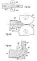
- Figure 8(a) shows an alternative arrangement for 'crimping' the crop column after formation by the primary compaction mechanism.
- the profiled rollers 178,179 may be undriven or driven and located as shown at 102 and 103 in Figure 5(a) at a variable centre distance.
- protrusions shown in Figures 7(a) and 7(b) may be sharpened at their leading edges, to achieve severing of crop during compression, at least in part of each charge.
- profiled rollers shown in Figure 8(a) were replaced by cylindrical spaces between sharpened discs, a cutting effect could also be achieved.
- Figure 8(b) is a view in direction of arrow A in Figure 8(a) and Figure 8(c) is a view in the direction of arrow B.
- the profiled rollers are shown mounted in fixed positions, their centre distance can be made adjustable, as mentioned earlier, or one roller may be arranged to be spring-loaded towards a limit stop in the direction of the other roller.
- Figures 9(a) and 9(b) show an alternative form of briquetting press, comprising essentially a large-diameter ring 120 and a smaller diameter roller 121 so placed inside the ring that the two components co-operate closely at the "12 o'clock" position 123. Jointly the ring and roller form a gradually converging, curved intake and pre-compaction region for crop entering at an angle as a pre-formed column beneath the roller.
- the ring 120 is supported on trunnion rollers 124 - 127 which have recesses to engage with a central rib 129 on the outer surfaces of the ring. In this way radial and axial support is provided.
- the roller 121 is supported in a heavy suspended saddle 131 which also carries a substantial backing roller 133 to support the main compressive load.
- the press roller is driven through reduction gears and is then geared to the ring at the required speed ratio, as illustrated, for example, in Figure 9(b).
- Briquette length- and width-defining protrusions, and elements (not shown) designed to give an additional indenting effect may be fitted to the co-operating surfaces of the press roller and ring in the combinations described previously in the context of the roller press configurations. If only the briquette width-defining circumferential ribs are fitted to one of the rotary components, it becomes possible to drive the ring and roller separately and, if desired, at differential speed.
- annular plate is attached to both sides of the ring 120.
- Briquettes made in the machine may be dislodged, if necessary, by optional scrapers and extracted from the press by means of a chute or the auger shown in Figure 9(a).
- a variation on the ring and roller press is possible by replacing the roller with a ring of similar diameter.
- FIG. 10(a) shows in plan view a pick-up baler 135 for collecting crop from the field comprising a pick-up device and a longitudinally reciprocating piston 137 for compacting the crop and force-feeding it through a converging duct 139 into the nip of a roller press 141.
- the press is designed as a trailed attachment to the baler and the common axis of the press roller centres lies at right angles to the crop flow. In an alternative embodiment (not shown) it may instead be designed to lie angularly displaced horizontally and/or vertically relative to the direction of crop flow.
- FIG 10(b) is a sectioned view in the direction of arrows GG in Figure 10(a) of the baler and trailed press.
- the baler is conventional in overall design, the height of the piston has been reduced to 250 mm. Absence of a knotting mechanism allows piston speed to be approximately doubled, relative to a conventional baler, and this permits normal throughput levels to be at least maintained.
- the operative height of the briquetting press rollers and the crop column guide plates relates to that of the baler piston. To achieve good feeding of the crop column into the nip of the briquetting rollers, the normal length of the bale chamber has been drastically shortened and the horizontal clearance between the downstream ends of the crop column guide plates is kept to around 300 mm.
Landscapes
- Engineering & Computer Science (AREA)
- Mechanical Engineering (AREA)
- Apparatuses For Bulk Treatment Of Fruits And Vegetables And Apparatuses For Preparing Feeds (AREA)
Claims (5)
dadurch gekennzeichnet,
Applications Claiming Priority (2)
| Application Number | Priority Date | Filing Date | Title |
|---|---|---|---|
| GB858509061A GB8509061D0 (en) | 1985-04-09 | 1985-04-09 | Briquetting fibrous crop &c material |
| GB8509061 | 1985-04-09 |
Publications (2)
| Publication Number | Publication Date |
|---|---|
| EP0197777A1 EP0197777A1 (de) | 1986-10-15 |
| EP0197777B1 true EP0197777B1 (de) | 1989-01-25 |
Family
ID=10577329
Family Applications (1)
| Application Number | Title | Priority Date | Filing Date |
|---|---|---|---|
| EP86302514A Expired EP0197777B1 (de) | 1985-04-09 | 1986-04-04 | Vorrichtung und Verfahren zum Brikettieren von faserigem Erntegut oder dergleichen |
Country Status (5)
| Country | Link |
|---|---|
| US (1) | US4798529A (de) |
| EP (1) | EP0197777B1 (de) |
| DE (1) | DE3661892D1 (de) |
| DK (1) | DK159086A (de) |
| GB (2) | GB8509061D0 (de) |
Families Citing this family (23)
| Publication number | Priority date | Publication date | Assignee | Title |
|---|---|---|---|---|
| MY101061A (en) * | 1986-03-13 | 1991-07-16 | Zenata Nv | Apparatus for briquetting coal |
| JPH02142732U (de) * | 1989-05-01 | 1990-12-04 | ||
| US5792485A (en) * | 1989-08-21 | 1998-08-11 | Korse; Theodorus H. | Pelleting press |
| GB2241919B (en) * | 1990-03-12 | 1993-06-02 | Marconi Electronic Devices | Method of manufacture |
| EP0498032A3 (en) * | 1991-02-02 | 1993-02-03 | Schaumann, Wilhelm H. | Process for preparing mineral feed or feed supplement nuggets |
| AT397216B (de) * | 1991-02-19 | 1994-02-25 | Zavernik Peter | Verfahren und vorrichtung zur herstellung von dreidimensionalen formkörpern aus einer flächigen bahn aus streckmetall |
| GB2261625B (en) * | 1991-10-31 | 1995-07-12 | Moy Park Ltd | Method and apparatus for sealing and/or shaping a food product |
| US5431942A (en) * | 1993-05-24 | 1995-07-11 | Moy Park Limited Of The Food Park | Method and apparatus for shaping food products |
| US6092753A (en) | 1993-06-01 | 2000-07-25 | Koenig; Larry E. | Material processing apparatus |
| JP4903334B2 (ja) | 1999-10-13 | 2012-03-28 | ノヴォ ノルディスク アー/エス | 細長の剤形を製造する方法 |
| GB0030340D0 (en) * | 2000-12-13 | 2001-01-24 | Sorex Ltd | Briquettes |
| US7452200B2 (en) * | 2005-03-30 | 2008-11-18 | Weyerhaeuser Company | Briquetting die for dispersible fiber briquettes |
| WO2007056685A2 (en) * | 2005-11-04 | 2007-05-18 | Wm. Wrigley Jr. Company | Apparatus for producing a center-filled confectionery and method |
| US20090047523A1 (en) * | 2007-08-13 | 2009-02-19 | Keedy Jr Vincent W | Production of discrete shaped article |
| US20090064569A1 (en) * | 2007-09-06 | 2009-03-12 | Abhay Kumar Khater | Pelletising of Fibrous Combustible Material at Variable Pressure and Variable Temperature |
| US20100040721A1 (en) * | 2008-08-12 | 2010-02-18 | Dec Roman T | Roller press for high pressure briquetting of biomass, low rank coals and other fibrous materials |
| JP5175693B2 (ja) * | 2008-11-21 | 2013-04-03 | 株式会社オーディオテクニカ | 米飯成形装置および同米飯成形装置の制御方法 |
| US20110219678A1 (en) * | 2010-03-12 | 2011-09-15 | Bepex International, Llc | Mold for forming compacted mass having a grooved surface |
| US8726800B2 (en) | 2010-08-23 | 2014-05-20 | 9177-4331 Québec inc. | Method and mechanical press system for the generation of densified cylindrical briquettes |
| EP2426243A1 (de) * | 2010-09-01 | 2012-03-07 | Benninger Zell GmbH | Vorrichtung und Verfahren zur Behandlung (Weichmachung) von kontinuierlich geförfertem Gut |
| DE102012017549B8 (de) * | 2012-09-05 | 2014-04-10 | Felix Kalverkamp | Vorrichtung zum Kompaktieren von Halmgut |
| CN108724795A (zh) * | 2018-06-13 | 2018-11-02 | 张家港天宇精梳羊毛有限公司 | 一种羊毛球堆高放置压缩装置 |
| JP7378083B2 (ja) * | 2019-12-24 | 2023-11-13 | パナソニックIpマネジメント株式会社 | 粉体成形装置 |
Family Cites Families (78)
| Publication number | Priority date | Publication date | Assignee | Title |
|---|---|---|---|---|
| US538475A (en) * | 1895-04-30 | Machine for making artificial fuel | ||
| DE59713C (de) * | E. STAUBER in Hamburg, Schlump Nr. 27 | Briketpresse | ||
| US492206A (en) * | 1893-02-21 | Machine for molding oval or other shapes from plastic material | ||
| US385697A (en) * | 1888-07-10 | Gustavis l | ||
| DE313674C (de) * | 1900-01-01 | |||
| US548155A (en) * | 1895-10-15 | Charles h | ||
| US785786A (en) * | 1904-03-25 | 1905-03-28 | Eduard Wolff | Machine for making corrugated wood sliver. |
| US1152468A (en) * | 1908-10-26 | 1915-09-07 | Zwoyer Fuel Company | Machine for making briquettes. |
| US1127925A (en) * | 1914-05-22 | 1915-02-09 | George Richard Schueler | Machine for compressing or molding plastic substances. |
| FR575946A (fr) * | 1924-01-25 | 1924-08-08 | Meguin A G | Presse à briquettes en forme de noix |
| DE673272C (de) * | 1935-08-02 | 1939-03-18 | Zeitzer Eisengiesserei Und Mas | Ringwalzenpresse |
| FR882365A (fr) * | 1942-01-26 | 1943-06-01 | Sahut | Presse à roues mouleuses pour la production d'agglomérés combustibles |
| US2367962A (en) * | 1943-02-13 | 1945-01-23 | Waterbury Co Inc | Apparatus for making all-plastic molded buttons |
| US2595865A (en) * | 1946-02-19 | 1952-05-06 | H C Rhodes | Doughnut forming machine |
| US2662246A (en) * | 1949-06-22 | 1953-12-15 | Monsanto Chemicals | Briquetting roll |
| GB713106A (en) * | 1951-11-28 | 1954-08-04 | Rose Brothers Ltd | Improvements in or relating to sweet-forming and wrapping machines |
| US2843879A (en) * | 1954-02-08 | 1958-07-22 | Komarek Greaves And Company | Method and apparatus for controlling material feed and air venting in briquetting machines |
| US2945259A (en) * | 1957-09-25 | 1960-07-19 | Kloeckner Humboldt Deutz Ag | Roller briquetting press for the briquetting of ore, coal or similar materials |
| US3024112A (en) * | 1958-07-10 | 1962-03-06 | Gen Foods Corp | Production of biscuits |
| BE581457A (de) * | 1958-08-12 | |||
| GB939759A (en) * | 1959-03-04 | 1963-10-16 | Massey Ferguson Services Nv | Apparatus for compacting hay or other forage crop |
| US3015199A (en) * | 1959-04-08 | 1962-01-02 | Ford Motor Co | Machine for compressing hay into cakes |
| US3149585A (en) * | 1960-01-05 | 1964-09-22 | Deere & Co | Material compressing machine |
| CA737226A (en) * | 1960-06-17 | 1966-06-28 | National Frost Protection Co. | Machine for forming pellets and the like |
| DE1176351B (de) * | 1960-10-07 | 1964-08-20 | Rudolph Scheffus Maschinenfabr | Strang- oder Bandpresse mit zwei walzen-aehnlichen Koerpern zum Zufuehren von Teigen, Pasten oder Fettmassen in die Druckkammer der Presse |
| NL285643A (de) * | 1961-11-20 | |||
| US3233393A (en) * | 1962-08-31 | 1966-02-08 | Massey Ferguson Services Nv | Machine for wafering standing forage crops |
| US3363588A (en) * | 1963-01-23 | 1968-01-16 | Deere & Co | Feed control means for forage crop wafering machine |
| GB1036931A (en) * | 1963-01-31 | 1966-07-20 | Cal Cube Inc | Improvements in machines and methods intended for pelletizing natural fodder |
| US3144840A (en) * | 1963-06-20 | 1964-08-18 | Sperry Rand Corp | Hay pelleter |
| GB1018519A (en) * | 1963-10-15 | 1966-01-26 | Rosemary Clare Hoare | Improvements in or relating to fuels |
| US3366717A (en) * | 1964-05-18 | 1968-01-30 | United States Steel Corp | Method and apparatus for controlling hot-briquetting operation |
| US3343257A (en) * | 1965-05-05 | 1967-09-26 | Automatic Elect Lab | Method of applying precious metal tip to base metal switch wiper |
| US3328843A (en) * | 1965-06-03 | 1967-07-04 | United States Steel Corp | Speed-control system for briquetting rolls |
| US3430583A (en) * | 1967-03-07 | 1969-03-04 | Int Harvester Co | Waferizing machine |
| DK109949C (da) * | 1967-06-01 | 1968-08-05 | Nielsen Alfred T | Apparat til brikettering af løst, trævlet eller filtret materiale, navnlig tørrede grøntafgrøder. |
| US3508486A (en) * | 1967-06-30 | 1970-04-28 | Joe Polich | Compressing machine |
| LU54422A1 (de) * | 1967-09-05 | 1969-06-24 | ||
| US3485016A (en) * | 1968-01-15 | 1969-12-23 | Deere & Co | Machine for wafering hay and like crops |
| GB1180898A (en) * | 1968-07-18 | 1970-02-11 | Glomera Ag | Feed Apparatus for Briquetting Presses. |
| DE1946821A1 (de) * | 1968-09-23 | 1970-09-24 | Alfa Laval Ab | Verfahren zum Herstellen selbsttragender Kuchen oder Waffeln aus Gruenernte und Vorrichtung zur Durchfuehrung dieses Verfahrens |
| DK128431B (da) * | 1969-02-10 | 1974-05-06 | A Nielsen | Fremgangsmåde ved brikettering af græs og lignende grøntafgrøder. |
| US3687067A (en) * | 1969-11-20 | 1972-08-29 | Bettcher Industries | Food press |
| CA933034A (en) * | 1969-11-20 | 1973-09-04 | Betts, Craig | Food press |
| US3723129A (en) * | 1970-05-27 | 1973-03-27 | Case Co J I | Bite-size body of hay |
| NL7104077A (de) * | 1971-03-26 | 1972-09-28 | ||
| DE2209991A1 (de) * | 1972-03-02 | 1973-09-13 | Fahr Ag Maschf | Stempelbrikettpresse, vorzugsweise zwillingsschubkurbelpresse fuer die brikettierung von koernigen und/oder faserigen landwirtschaftlichen produkten, insbesondere von gruenfutter |
| US3838001A (en) * | 1972-06-15 | 1974-09-24 | Johns Manville | Assembly for press-forming sheet material |
| DE2239281C3 (de) * | 1972-08-10 | 1984-05-30 | Dynamit Nobel Ag, 5210 Troisdorf | Verfahren zur Herstellung von mit einer Hülle umgebenen Sprengstoffkörpern |
| US3829267A (en) * | 1972-10-31 | 1974-08-13 | Kennametal Inc | Briquetting apparatus and die member arrangement therefor |
| US3899964A (en) * | 1973-01-29 | 1975-08-19 | Joseph Molitorisz | Rotary hay-briqueting machine for compacting fibrous material |
| US3889884A (en) * | 1973-02-09 | 1975-06-17 | George W Morse | Hay product and method for forming |
| SU488545A1 (ru) * | 1973-06-14 | 1975-10-25 | Армянский Научно-Исследовательский Институт Механизации И Электрификации Сельского Хозяйства | Брикетный пресс |
| US4018149A (en) * | 1973-10-22 | 1977-04-19 | Bjorn Adler Zeuthen Bruun | Press for production of a dry fodder |
| US3923316A (en) * | 1973-12-27 | 1975-12-02 | Richard S Birnbaum | Grass-ski |
| DE2401666A1 (de) * | 1974-01-15 | 1975-07-24 | Muehlmeyer Franz | Aufsammelpresse zur strohpelletisierung |
| SU641935A1 (ru) * | 1974-07-12 | 1979-01-15 | Yavorskij Alfred A | Устройство дл гранулировани трав ной муки |
| US3973484A (en) * | 1974-10-29 | 1976-08-10 | Jarrett Ronald T | Hay presser apparatus |
| US3946660A (en) * | 1974-11-12 | 1976-03-30 | Kuehtreiber F | Process for utilising straw |
| FR2346121A2 (fr) * | 1975-06-03 | 1977-10-28 | Cordi Sa | Procede d'agglomeration de substances minerales comprimables sous forme de poudre, particules ou fibres |
| SU694129A1 (ru) * | 1976-06-23 | 1979-10-30 | Научно-исследовательский и проектно-технологический институт механизации и электрификации сельского хозяйства Нечерноземной зоны РСФСР | Способ заготовки сена из растительной массы |
| SU656610A1 (ru) * | 1976-12-03 | 1979-04-15 | Научно-Исследовательский Институт Сельского Хозяйства Центральных Районов Нечерноземной Зоны Рсфср | Способ приготовлени корма |
| GB1540869A (en) * | 1976-12-20 | 1979-02-14 | Chloride Silent Power Ltd | Electrode structures |
| DK142394B (da) * | 1977-08-04 | 1980-10-27 | Mogens Robert Berthelsen | Presseapparat, fortrinsvis til presning af stråformet materiale. |
| SU677719A1 (ru) * | 1978-01-04 | 1979-08-05 | Армянский Научно-Исследовательский Институт Механизации И Электрификации Сельского Хозяйства | Брикетный пресс |
| SU680685A1 (ru) * | 1978-01-12 | 1979-08-25 | Армянский Научно-Исследовательский Институт Механизации И Электрификации Сельского Хозяйства | Устройство дл изготовлени сенных брикетов |
| US4182604A (en) * | 1978-02-13 | 1980-01-08 | Keith Manufacturing | Blocking machine |
| SU698577A1 (ru) * | 1978-07-25 | 1979-11-25 | Челябинский Институт Механизации И Электрификации Сельского Хозяйства | Пресс дл сеносоломистых материалов |
| SU829034A1 (ru) * | 1979-01-26 | 1981-05-15 | Челябинский Институт Механизациии Электрификации Сельского Хозяйства | Штемпельный пресс дл брикетировани СЕНО-СОлОМиСТыХ МАТЕРиАлОВ |
| EP0027824B1 (de) * | 1979-04-29 | 1985-01-16 | OSATO, Akira | Unter druck geformter faseriger stoff und formpresse dafür |
| DD145697A1 (de) * | 1979-09-06 | 1981-01-07 | Gerd Bernhardt | Anlage zur produktion von trockenfuttermitteln |
| FI59240C (fi) * | 1979-10-24 | 1981-07-10 | Farmos Oy | Foerfarande och anordning foer pressning av torv till vaextsubstratstycken |
| GB2071560B (en) * | 1980-02-20 | 1983-06-22 | Beal P R | Straw logs |
| DE3107744A1 (de) * | 1981-02-28 | 1982-09-16 | Gummi-Jäger KG GmbH & Cie, 3000 Hannover | Rollpresse fuer heu, stroh und dgl. |
| DE3129788A1 (de) * | 1981-07-29 | 1983-02-17 | Claas Ohg, 4834 Harsewinkel | Strohbrikettpresse |
| US4437826A (en) * | 1982-07-30 | 1984-03-20 | Akitomi Tezuka | Rice-body shaping device for rolled sushi |
| GB8414244D0 (en) * | 1984-06-05 | 1984-07-11 | Bernewode Designs Ltd | Mobile forage cubing machine |
| GB2161742B (en) * | 1984-07-20 | 1988-08-17 | Howard Machinery Plc | Processing crop material |
-
1985
- 1985-04-09 GB GB858509061A patent/GB8509061D0/en active Pending
-
1986
- 1986-04-04 EP EP86302514A patent/EP0197777B1/de not_active Expired
- 1986-04-04 DE DE8686302514T patent/DE3661892D1/de not_active Expired
- 1986-04-04 GB GB8608287A patent/GB2173443B/en not_active Expired
- 1986-04-08 DK DK159086A patent/DK159086A/da not_active IP Right Cessation
- 1986-04-09 US US06/849,942 patent/US4798529A/en not_active Expired - Fee Related
Also Published As
| Publication number | Publication date |
|---|---|
| GB2173443B (en) | 1989-07-05 |
| GB8608287D0 (en) | 1986-05-08 |
| EP0197777A1 (de) | 1986-10-15 |
| US4798529A (en) | 1989-01-17 |
| GB8509061D0 (en) | 1985-05-15 |
| GB2173443A (en) | 1986-10-15 |
| DE3661892D1 (en) | 1989-03-02 |
| DK159086D0 (da) | 1986-04-08 |
| DK159086A (da) | 1986-10-10 |
Similar Documents
| Publication | Publication Date | Title |
|---|---|---|
| EP0197777B1 (de) | Vorrichtung und Verfahren zum Brikettieren von faserigem Erntegut oder dergleichen | |
| CN104755257B (zh) | 用于压缩纤维状植物材料、尤其是用于压缩秸秆材料的装置 | |
| CA2128523C (en) | Device for pelletizing vegetable material | |
| US4824352A (en) | Apparatus for pelletizing materials | |
| CN112166839A (zh) | 一种秸秆铡草揉丝机 | |
| CN210226269U (zh) | 秸秆收集粉碎造粒一体机 | |
| CN215512404U (zh) | 一种汽车零部件的废旧金属打包机 | |
| CN214155444U (zh) | 一种秸秆铡草揉丝机 | |
| CN211637701U (zh) | 一种新鲜玉米秸秆榨汁-粉碎-成型一体化装置 | |
| US20130309344A1 (en) | Double die pellet machine | |
| CN213644240U (zh) | 一种出料尺寸可调的压片破碎机 | |
| EP0231559B1 (de) | Ernteverarbeitungsvorrichtung | |
| US3363587A (en) | Hay wafering machine | |
| WO1997036722A1 (en) | Briquet forming machine | |
| CN2524832Y (zh) | 剪切式干式造粒机 | |
| CN110734798A (zh) | 一种秸秆生物质颗粒燃料制备预处理系统 | |
| CN110842014A (zh) | 一种新鲜玉米秸秆榨汁-粉碎-成型一体化装置 | |
| CN217657199U (zh) | 一种粉碎机秸秆喂料机构 | |
| CN2479745Y (zh) | 秸秆碾碎机 | |
| RU2021897C1 (ru) | Брикетный пресс | |
| CN212910814U (zh) | 秸秆粉碎机 | |
| CN112223818B (zh) | 煤泥成型给料机 | |
| CN219459811U (zh) | 一种用于饲草料粉碎机的挤压机构及饲草料粉碎机 | |
| RU1794397C (ru) | Устройство дл измельчени грубых кормов | |
| CN219210577U (zh) | 一种生物有机肥加工用筛分系统 |
Legal Events
| Date | Code | Title | Description |
|---|---|---|---|
| PUAI | Public reference made under article 153(3) epc to a published international application that has entered the european phase |
Free format text: ORIGINAL CODE: 0009012 |
|
| AK | Designated contracting states |
Kind code of ref document: A1 Designated state(s): DE FR NL |
|
| 17P | Request for examination filed |
Effective date: 19870109 |
|
| 17Q | First examination report despatched |
Effective date: 19871019 |
|
| GRAA | (expected) grant |
Free format text: ORIGINAL CODE: 0009210 |
|
| AK | Designated contracting states |
Kind code of ref document: B1 Designated state(s): DE FR NL |
|
| REF | Corresponds to: |
Ref document number: 3661892 Country of ref document: DE Date of ref document: 19890302 |
|
| ET | Fr: translation filed | ||
| PLBE | No opposition filed within time limit |
Free format text: ORIGINAL CODE: 0009261 |
|
| STAA | Information on the status of an ep patent application or granted ep patent |
Free format text: STATUS: NO OPPOSITION FILED WITHIN TIME LIMIT |
|
| 26N | No opposition filed | ||
| PGFP | Annual fee paid to national office [announced via postgrant information from national office to epo] |
Ref country code: FR Payment date: 19920429 Year of fee payment: 7 |
|
| PGFP | Annual fee paid to national office [announced via postgrant information from national office to epo] |
Ref country code: NL Payment date: 19920430 Year of fee payment: 7 |
|
| PGFP | Annual fee paid to national office [announced via postgrant information from national office to epo] |
Ref country code: DE Payment date: 19920630 Year of fee payment: 7 |
|
| REG | Reference to a national code |
Ref country code: FR Ref legal event code: TP |
|
| NLS | Nl: assignments of ep-patents |
Owner name: BRITISH TECHNOLOGY GROUP LTD TE LONDEN, GROOT-BRIT |
|
| PG25 | Lapsed in a contracting state [announced via postgrant information from national office to epo] |
Ref country code: NL Effective date: 19931101 |
|
| NLV4 | Nl: lapsed or anulled due to non-payment of the annual fee | ||
| PG25 | Lapsed in a contracting state [announced via postgrant information from national office to epo] |
Ref country code: FR Effective date: 19931229 |
|
| REG | Reference to a national code |
Ref country code: FR Ref legal event code: ST |
|
| PG25 | Lapsed in a contracting state [announced via postgrant information from national office to epo] |
Ref country code: DE Effective date: 19940503 |