EP0197296B1 - Schaltbare Vorrichtung zur Walzenan- und -abstellung in Farb- und/oder Feuchtwerken von Druckmaschinen - Google Patents
Schaltbare Vorrichtung zur Walzenan- und -abstellung in Farb- und/oder Feuchtwerken von Druckmaschinen Download PDFInfo
- Publication number
- EP0197296B1 EP0197296B1 EP86102785A EP86102785A EP0197296B1 EP 0197296 B1 EP0197296 B1 EP 0197296B1 EP 86102785 A EP86102785 A EP 86102785A EP 86102785 A EP86102785 A EP 86102785A EP 0197296 B1 EP0197296 B1 EP 0197296B1
- Authority
- EP
- European Patent Office
- Prior art keywords
- lever
- application
- lifting
- coupling
- handle
- Prior art date
- Legal status (The legal status is an assumption and is not a legal conclusion. Google has not performed a legal analysis and makes no representation as to the accuracy of the status listed.)
- Expired - Lifetime
Links
- 238000007639 printing Methods 0.000 title claims abstract description 7
- 238000013016 damping Methods 0.000 title claims abstract 3
- 230000008878 coupling Effects 0.000 claims abstract description 20
- 238000010168 coupling process Methods 0.000 claims abstract description 20
- 238000005859 coupling reaction Methods 0.000 claims abstract description 20
- 230000003213 activating effect Effects 0.000 claims 3
- 230000004913 activation Effects 0.000 claims 2
- 238000006073 displacement reaction Methods 0.000 description 1
- 238000007645 offset printing Methods 0.000 description 1
- 238000005096 rolling process Methods 0.000 description 1
Images

Classifications
-
- B—PERFORMING OPERATIONS; TRANSPORTING
- B41—PRINTING; LINING MACHINES; TYPEWRITERS; STAMPS
- B41F—PRINTING MACHINES OR PRESSES
- B41F31/00—Inking arrangements or devices
- B41F31/30—Arrangements for tripping, lifting, adjusting, or removing inking rollers; Supports, bearings, or forks therefor
- B41F31/32—Lifting or adjusting devices
-
- Y—GENERAL TAGGING OF NEW TECHNOLOGICAL DEVELOPMENTS; GENERAL TAGGING OF CROSS-SECTIONAL TECHNOLOGIES SPANNING OVER SEVERAL SECTIONS OF THE IPC; TECHNICAL SUBJECTS COVERED BY FORMER USPC CROSS-REFERENCE ART COLLECTIONS [XRACs] AND DIGESTS
- Y10—TECHNICAL SUBJECTS COVERED BY FORMER USPC
- Y10T—TECHNICAL SUBJECTS COVERED BY FORMER US CLASSIFICATION
- Y10T403/00—Joints and connections
- Y10T403/32—Articulated members
- Y10T403/32254—Lockable at fixed position
- Y10T403/32262—At selected angle
- Y10T403/32319—At selected angle including pivot stud
- Y10T403/32327—At selected angle including pivot stud including radially spaced detent or latch component
- Y10T403/32336—Engaging notch or recess in outer periphery of component
-
- Y—GENERAL TAGGING OF NEW TECHNOLOGICAL DEVELOPMENTS; GENERAL TAGGING OF CROSS-SECTIONAL TECHNOLOGIES SPANNING OVER SEVERAL SECTIONS OF THE IPC; TECHNICAL SUBJECTS COVERED BY FORMER USPC CROSS-REFERENCE ART COLLECTIONS [XRACs] AND DIGESTS
- Y10—TECHNICAL SUBJECTS COVERED BY FORMER USPC
- Y10T—TECHNICAL SUBJECTS COVERED BY FORMER US CLASSIFICATION
- Y10T403/00—Joints and connections
- Y10T403/60—Biased catch or latch
- Y10T403/602—Biased catch or latch by separate spring
- Y10T403/604—Radially sliding catch
-
- Y—GENERAL TAGGING OF NEW TECHNOLOGICAL DEVELOPMENTS; GENERAL TAGGING OF CROSS-SECTIONAL TECHNOLOGIES SPANNING OVER SEVERAL SECTIONS OF THE IPC; TECHNICAL SUBJECTS COVERED BY FORMER USPC CROSS-REFERENCE ART COLLECTIONS [XRACs] AND DIGESTS
- Y10—TECHNICAL SUBJECTS COVERED BY FORMER USPC
- Y10T—TECHNICAL SUBJECTS COVERED BY FORMER US CLASSIFICATION
- Y10T74/00—Machine element or mechanism
- Y10T74/20—Control lever and linkage systems
- Y10T74/20207—Multiple controlling elements for single controlled element
-
- Y—GENERAL TAGGING OF NEW TECHNOLOGICAL DEVELOPMENTS; GENERAL TAGGING OF CROSS-SECTIONAL TECHNOLOGIES SPANNING OVER SEVERAL SECTIONS OF THE IPC; TECHNICAL SUBJECTS COVERED BY FORMER USPC CROSS-REFERENCE ART COLLECTIONS [XRACs] AND DIGESTS
- Y10—TECHNICAL SUBJECTS COVERED BY FORMER USPC
- Y10T—TECHNICAL SUBJECTS COVERED BY FORMER US CLASSIFICATION
- Y10T74/00—Machine element or mechanism
- Y10T74/20—Control lever and linkage systems
- Y10T74/20576—Elements
- Y10T74/20582—Levers
- Y10T74/20612—Hand
- Y10T74/20618—Jointed
-
- Y—GENERAL TAGGING OF NEW TECHNOLOGICAL DEVELOPMENTS; GENERAL TAGGING OF CROSS-SECTIONAL TECHNOLOGIES SPANNING OVER SEVERAL SECTIONS OF THE IPC; TECHNICAL SUBJECTS COVERED BY FORMER USPC CROSS-REFERENCE ART COLLECTIONS [XRACs] AND DIGESTS
- Y10—TECHNICAL SUBJECTS COVERED BY FORMER USPC
- Y10T—TECHNICAL SUBJECTS COVERED BY FORMER US CLASSIFICATION
- Y10T74/00—Machine element or mechanism
- Y10T74/20—Control lever and linkage systems
- Y10T74/20576—Elements
- Y10T74/20732—Handles
- Y10T74/20762—Shaft connections
Definitions
- the invention relates to a switchable device for switching rollers on and off in inking and / or dampening units of printing presses, which can be operated automatically in two operating modes either via the pressure circuit or by hand and in which a torque effecting the respective actuating movement is achieved by means of a non-positive coupling a spring-loaded, manually releasable automatically engaging connecting element is transferable.
- a device of this type is known from practice.
- the disadvantage is that the frictional coupling is produced in both modes with the same connecting element.
- the clutch has to be released by hand by axially moving a spring-loaded wedge from a groove of a lever intended for automatic operation so that the roller can be switched on and off independently of the pressure circuit using a shift lever.
- the previously released, spring-loaded wedge engages again automatically under the action of the spring. Since the spring-loaded wedge always remains firmly connected to the gearshift lever, when the rollers are switched on and off automatically, an inherently undesirable torque is also transmitted to the gearshift lever for manual operation. This creates a permanent risk of accident for the operator, because the shift lever can be used to squeeze the hand and arm if the rollers and shutters are accidentally actuated at the same time.
- the invention is therefore based on the object to provide a switchable device of the type mentioned, which makes it possible to switch between the operating modes automatic operation and manual operation in a space-saving arrangement of the non-positive clutch without a torque with the shift lever for manual operation in automatic operation to be able to transmit.
- the advantage of the invention is that the roll start and stop can be switched with reduced risk of accident and at the same time a space-saving arrangement of the non-positive coupling is ensured.
- the applicator rollers of an inking unit are pivoted in a known manner, for example by means of a switching shaft (not shown), of which only one coupling element 1 is shown for switching the roller on and off.
- the application rollers are coupled to the pressure circuit and automatically turn on and off with the pressure.
- a coupling member 2 which is mounted on a pin 3 in a first on and off lever 4, can be pivoted when the pressure is switched on and off.
- the first on and off lever 4 is mounted on a bushing 5 which is located on a cylinder fitting screw 6 which is fastened to the inside of the machine frame 7.
- a locking bolt 8 establishes a positive connection to a second on and off lever 9, which is arranged in a ring concentrically above the first on and off lever 4.
- the locking bolt 8 is slidably mounted in a bearing bush 10 which is radially fastened in the first actuating and deactivating lever 4 and is held under the pressure of a spring 11 against a sliding surface 12 on a pin 19 of a switching handle 13 provided on the locking bolt 8.
- the control handle 13 with pin 19 is radially displaceably mounted in a control lever 14, which is arranged concentrically in a ring above the second up and down lever 9.
- the stroke size of the radial displacement movement is exactly limited by means of a knurled screw 15 guided in a groove 20 of the control handle 13.
- the control handle 13 always remains in the disengaged position under the action of the spring 11, so that a torque via the first actuating and deactivating lever 4, the locking bolt 8, the second actuating and deactivating lever 9 and the coupling member 1 adjustably mounted on an eccentric bolt 16 automatic roller shutdown un space-saving arrangement can be transmitted without moving the control handle 13.
- a cylinder pin 17 and a resilient pressure piece 18 also prevent the rotary movement of the shift lever 14. With automatic operation of the roller and shutdown, it is also always ensured that there is no risk of crushing and crushing the hand and arm of the operator.
- the pin 19 establishes a non-positive connection to the second lever 9. After releasing the control handle 13, the pin 19 with the control handle 13 and the locking bolt 8 automatically snap back into the original position, so that the automatic operation of the roller and shutdown is automatically ensured again.
Landscapes
- Inking, Control Or Cleaning Of Printing Machines (AREA)
- Rotary Presses (AREA)
- Mechanical Control Devices (AREA)
- Inks, Pencil-Leads, Or Crayons (AREA)
Description
- Die Erfindung betrifft eine schaltbare Vorrichtung zur Walzenan- und- abstellung in Farb- und/ oder Feuchtwerken von Druckmaschinen, die in zwei Betriebsarten wahlweise automatisch über die Druckschaltung oder von Hand betätigbar ist und bei der ein die jeweilige Stellbewegung bewirkendes Drehmoment mit einer kraftschlüssigen Kupplung mittels eines gefederten, von Hand lösbaren selbsttätig einkuppelnden Verbindungselementes übertragbar ist.
- Eine Vorrichtung dieser Gattung ist aus der Praxis bekannt. Von Nachteil ist, daß die kraftschlüssige Kupplung in beiden Betriebsarten mit dem gleichen Verbindungselement hergestellt wird. Die Kupplung muß hierzu durch raumgreifendes axiales Verschieben eines gefederten Keiles aus einer Nut eines für den automatischen Betrieb vorgesehenen An- und Abstellhebels von Hand gelöst werden, damit die Walzenan- und -abstellung unabhängig von der Druckschaltung mit einem Schalthebel vorgenommen werden kann. Beim Loslassen kuppelt der zuvor gelöste, gefederte Keil unter der Wirkung der Feder wieder selbstständig ein. Da der gefederte Keil stets in fester Verbindung mit dem Schalthebel bleibt, wird bei automatischerWalzenan- und -abstellung ein an sich unerwünschtes Drehmoment auch auf den Schalthebel für den Handbetrieb übertragen. Für den Bedienenden besteht hieraus eine permanente Unfallgefahr, weil durch den erfaßten Schalthebel Hand und Arm gestaucht werden können, wenn die Walzenen- und -abstellung zufällig gleichzeitig automatisch betätigt wird.
- Letzteres gilt aus für die aus der US-A--3 067 674 bekannte Vorrichtung zum An- und Abschalten der Zylinder einer Offsetdruckmaschine entweder automatisch durch von Druckmittelzylindern über ein Schwenkgetriebe verdrehbare Exzenterbuchsen oder durch wahlweise von Hand verdrehbare Exzenterbuchsen mittels Handgriff, der in fester Antriebsverbindung mit dem Schwenkgetriebe steht.
- Der Erfindung liegt daher die Aufgabe zugrunde, eine schaltbare Vorrichtung eingangs genannter Gattung zu Schaffen, die es ermöglicht, zwischen den Betriebsarten automatischer Betrieb und Handbetrieb in raumsparender Anordnung der kraftschlüssigen Kupplung umzuschalten, ohne dabei mit dem Schalthebel für den Handbetrieb in einem automatischen Betrieb ein Drehmoment übertragen zu können.
- Diese Aufgabe wird gemäß dem kennzeichnenden Teil des ersten Anspruchs gelöst.
- Der Vorteil der Erfindung besteht darin, daß die Walzenan- und -abstellung oben genannter Gattung mit verminderter Unfallgefahr schaltbar ist und zugleich eine raumsparende Anordnung der kraftschlüssigen Kupplung gewährleistet ist.
- Anhand eines Ausführungsbeispieles wird die Erfindung nachfolgend näher erläutert.
- Es zeigen:
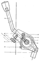
- Fig. eine schaltbare Vorrichtung zur Walzenan-und -abstellung als Teilansicht,
- Fig. 2 die Vorrichtung gemäß Fig. 1 im Schnitt.
- Zum An- und Abstellen von der Druckform werden die Auftragwalzen eines Farbwerkes in bekannter Weise beispielsweise mittels einer nicht dargestellten Schaltwelle verschwenkt, von der nur ein Koppelglied 1 zur Walzenan- und abstellung dargestellt ist. Die Auftragwalzen sind mit der Druckschaltung gekuppelt und stellen sich mit dem Druck automatisch an und ab. Hierzu ist ein Koppelglied 2, das auf einem Bolzen 3 in einem ersten An- und Abstellhebel 4 gelagert ist, bei Druckan- und -abstellung verschwenkbar. Der erste An- und Abstellhebel 4 ist auf einer Buchse 5 gelagert, die sich auf einer Zylinderpaßschraube 6 befindet, welche innen am Maschinengestell 7 befestigt ist. Ein Arretierbolzen 8 stellt eine formschlüssige Verbindung zu einem zweiten An- und Abstellhebel 9 her, der ringförmig konzentrisch über dem ersten An- und Abstellhebel 4 angeordnet ist. Der Arretierbolzen 8 ist in einer in dem ersten An- un Abstellhebel 4 radial befestigten Lagerbuchse 10 gleitend gelagert und wird unter dem Druck einer Feder 11 gegen eine Gleitfläche 12 an einem am Arretierbolzen 8 vorhandenen Zapfen 19 eines Schaltgriffes 13 gehalten. Der Schaltgriff 13 mit Zapfen 19 ist radial verschiebbar in einem Schalthebel 14 gelagert, der ringförmig konzentrisch über dem zweiten An- und Abstehhebel 9 angeordnet ist. Die Hubgröße der radialen Verschiebbewegung ist mittels einer in einer Nut 20 des Schaltgriffes 13 geführten Rändelschraube 15 exakt begrenzt. Der Schaltgriff 13 bleibt unter der Wirkung der Feder 11 stets in ausgekuppelter Stellung, so daß ein Drehmoment über den ersten An- und Abstellhebel 4, den Arretierbolzen 8, den zweiten An- und Abstellhebel 9 und das auf einem Exzenterbolzen 16 einstellbar gelagerte Koppelglied 1 zur automatischen Walzenabstellung un raumsparender Anordnung übertragen werden kann, ohne dabei den Schaltgriff 13 zu bewegen. Ein Zylinderstift 17 und ein federndes Druckstück 18 verhindern zugleich die Drehbewegung des Schalthebels 14. Bei automatischem Betrieb der Walzenen- und -abstellung ist außerdem stets gewährleistet, daß keine Stauch- und Quetschgefähr für Hand und Arm des Bedienenden besteht.
- Wird durch Eindrücken des Schaltgriffes 13 der Arretierbolzen 8 aus dem zweiten An- und Abstellhebel 9 entsprechend dem Hub entfernt und somit die Verbindung aufgehoben, kann der manuelle Betrieb der Walzenen- und -abstellung ausgeführt werden. Hierzu stellt der Zapfen 19 eine kraftschlüssige Verbindung zum zweiten An- und Abstellhebel 9 her. Nach Loslassen des Schaltgriffes 13 rasten der Zapfen 19 mit dem Schaltgriff 13 sowie der Arretierbolzen 8 automatisch in die Ursprungslage zurück, so daß der automatische Betrieb der Walzenen- und -abstellung selbsttätig wieder gewährleistet ist.
-
- 1 Koppelglied
- 2 Koppelglied
- 3 Bolzen
- 4 An- und Abstellhebel
- 5 Buchse
- 6 Zylinderpaßschraube
- 7 Maschinengestell
- 8 Arretierbolzen
- 9 An- und Abstellhebel
- 10 Lagerbuchse
- 11 Feder
- 12 Gleitfäche
- 13 Schaltgriff
- 14 Schalthebel
- 15 Rändelschraube
- 16 Exzenterbolzen
- 17 Zylinderstift
- 18 Druckstück
- 19 Zapfen
- 20 Nut
Claims (2)
Priority Applications (1)
| Application Number | Priority Date | Filing Date | Title |
|---|---|---|---|
| AT86102785T ATE54101T1 (de) | 1985-03-12 | 1986-03-04 | Schaltbare vorrichtung zur walzenan- und abstellung in farb- und/oder feuchtwerken von druckmaschinen. |
Applications Claiming Priority (2)
| Application Number | Priority Date | Filing Date | Title |
|---|---|---|---|
| DE3508661A DE3508661C1 (de) | 1985-03-12 | 1985-03-12 | Kuppelvorrichtung einer automatisch schaltbaren Walzenan- und -abstellung in Farb- und/oder Feuchtwerken von Druckmaschinen |
| DE3508661 | 1985-03-12 |
Publications (3)
| Publication Number | Publication Date |
|---|---|
| EP0197296A2 EP0197296A2 (de) | 1986-10-15 |
| EP0197296A3 EP0197296A3 (en) | 1987-10-07 |
| EP0197296B1 true EP0197296B1 (de) | 1990-06-27 |
Family
ID=6264868
Family Applications (1)
| Application Number | Title | Priority Date | Filing Date |
|---|---|---|---|
| EP86102785A Expired - Lifetime EP0197296B1 (de) | 1985-03-12 | 1986-03-04 | Schaltbare Vorrichtung zur Walzenan- und -abstellung in Farb- und/oder Feuchtwerken von Druckmaschinen |
Country Status (6)
| Country | Link |
|---|---|
| US (1) | US4699053A (de) |
| EP (1) | EP0197296B1 (de) |
| JP (1) | JPS61273965A (de) |
| AT (1) | ATE54101T1 (de) |
| BR (1) | BR8601262A (de) |
| DE (1) | DE3508661C1 (de) |
Families Citing this family (3)
| Publication number | Priority date | Publication date | Assignee | Title |
|---|---|---|---|---|
| US5033381A (en) * | 1987-02-06 | 1991-07-23 | Am International, Inc. | Adjustable mounting bracket for printing or duplicating machine roller |
| DE4230937A1 (de) * | 1992-09-16 | 1994-03-17 | Heidelberger Druckmasch Ag | Einrichtung zum Ein- und Auskuppeln von Farb- und Feuchtwerkantrieb |
| CN104890280B (zh) * | 2015-05-07 | 2017-03-22 | 博艳萍 | 一种握杆操作式压轮机构 |
Family Cites Families (10)
| Publication number | Priority date | Publication date | Assignee | Title |
|---|---|---|---|---|
| US3067674A (en) * | 1961-03-14 | 1962-12-11 | Miehle Goss Dexter Inc | Throw-off mechanism for offset presses |
| US3412676A (en) * | 1965-07-07 | 1968-11-26 | Dick Co Ab | Automated control system and apparatus for offset duplicating machine |
| US3457857A (en) * | 1966-07-29 | 1969-07-29 | Addressograph Multigraph | Control system for master processing and duplicating |
| DE2809166A1 (de) * | 1978-03-03 | 1979-09-13 | Bosch Gmbh Robert | Antriebsvorrichtung fuer einrichtungen zum verstellen von wandteilen, beispielsweise fenstern, schiebetueren u.dgl. von kraftfahrzeugen |
| US4203291A (en) * | 1979-03-29 | 1980-05-20 | J. I. Case Company | Control mechanism for hydrostatic pump |
| DE8100644U1 (de) * | 1981-01-14 | 1981-05-14 | Ernst Leitz Wetzlar Gmbh, 6330 Wetzlar | Mikrotomantrieb |
| FR2501813B1 (fr) * | 1981-03-13 | 1986-06-13 | Amiot Expl Procedes Felix | Perfectionnements aux dispositifs pour accoupler selectivement a un arbre a entrainer deux organes entraineurs distincts |
| FR2519063A1 (fr) * | 1981-12-30 | 1983-07-01 | Carpano & Pons | Dispositif auxiliaire de commande pour portes ou grilles enroulables, portes selectionnelles ou similaires |
| JPS58121338A (ja) * | 1982-01-11 | 1983-07-19 | Nec Corp | マイタギアボツクスの手動駆動装置 |
| CS239676B1 (en) * | 1983-11-09 | 1986-01-16 | Vaclav Sedlak | Mechanism for automatic control of printing pressure |
-
1985
- 1985-03-12 DE DE3508661A patent/DE3508661C1/de not_active Expired
-
1986
- 1986-03-04 AT AT86102785T patent/ATE54101T1/de not_active IP Right Cessation
- 1986-03-04 EP EP86102785A patent/EP0197296B1/de not_active Expired - Lifetime
- 1986-03-10 US US06/838,293 patent/US4699053A/en not_active Expired - Fee Related
- 1986-03-12 JP JP61052767A patent/JPS61273965A/ja active Granted
- 1986-03-12 BR BR8601262A patent/BR8601262A/pt not_active IP Right Cessation
Also Published As
| Publication number | Publication date |
|---|---|
| EP0197296A2 (de) | 1986-10-15 |
| BR8601262A (pt) | 1986-12-02 |
| ATE54101T1 (de) | 1990-07-15 |
| EP0197296A3 (en) | 1987-10-07 |
| DE3508661C1 (de) | 1986-10-16 |
| US4699053A (en) | 1987-10-13 |
| JPS61273965A (ja) | 1986-12-04 |
| JPH0517862B2 (de) | 1993-03-10 |
Similar Documents
| Publication | Publication Date | Title |
|---|---|---|
| EP0242661B1 (de) | Stellvorrichtung für Fünfzylinderdruckwerke von Offset-Rotationsdruckmaschinen | |
| DD151134A1 (de) | Antrieb fuer funktionsgruppen in bogenfuehrungszylindern von druckmaschinen | |
| DE4110035C2 (de) | Vorrichtung zum Verstellen von Elementen in Falzwerkzylindern von Rotationsdruckmaschinen | |
| EP0340452A2 (de) | Vorrichtung zur Verstellung der Drehlage eines Zylinders einer Wendeeinrichtung und zur axialen Verschiebung eines Stellgliedes für die Greiferumstellung an diesem Zylinder einer Bogenrotationsdruckmaschine | |
| EP0010141A1 (de) | Vorrichtung zum Herstellen von Druckerzeugnissen mit wechselnden Eindrucken | |
| EP0736384A1 (de) | Vorrichtung zur Druckan- und -abstellung | |
| EP0442265B1 (de) | Klemmvorrichtung für ein axial verschiebbares Stellglied zur Greiferumsteuerung an einem Greiferzylinder einer Bogenrotationsdruckmaschine | |
| EP0197296B1 (de) | Schaltbare Vorrichtung zur Walzenan- und -abstellung in Farb- und/oder Feuchtwerken von Druckmaschinen | |
| DE3112382C2 (de) | Hubverstelleinrichtung für Exzenterpressen oder -stanzen | |
| DE4401684C2 (de) | Verstelleinrichtung für eine Druckmaschine | |
| DE4140048C2 (de) | Farbwerk einer Druckmaschine, insbesondere Bogenoffsetdruckmaschine | |
| EP0096246B1 (de) | Kupplungsvorrichtung für ein Stellrad | |
| DE2901236A1 (de) | Vorrichtung zum verstellen des antriebes an bogenrotationsdruckmaschinen fuer wahlweisen schoen- oder schoen- und widerdruck | |
| DE4111636C1 (de) | ||
| DE2740658C3 (de) | Formschlussige Kupplung zwischen Etikettiermaschine und einer mit einem Antrieb versehenen Füllmaschine | |
| DE3440866C2 (de) | ||
| DE2102994B2 (de) | Antriebsvorrichtung für die Vorschubbewegungen von Werkzeugmaschinenschlitten | |
| DE2135483B2 (de) | Sicherheitskupplung, insbesondere in einem von einer Presse abgeleiteten Antrieb einer Werkstücktransportvorrichtung | |
| DE10347152B4 (de) | Kurvensteuervorrichtung für ein Bogenhaltesystem in einer Verarbeitungsmaschine | |
| DE3521396C1 (de) | Kupplungsvorrichtung zum Umschalten zwischen Motor- und Handbetätigung eines Stellantriebes | |
| EP0588188B1 (de) | Einrichtung zum Ein- und Auskuppeln von Farb- und Feuchtwerkantrieb | |
| DD297118A5 (de) | Vorrichtung zur druckan- abstellung | |
| DE3535865A1 (de) | Einrichtung zur hubverstellung an exzenterpressen | |
| DE2361896C2 (de) | Einrichtung zum Steuern und gegenseitigen Sperren mindestens zweier Kupplungen an kraftangetriebenen Druckwerken | |
| DE650645C (de) | Vorrichtung zum Ein- und Ausruecken der Klauenkupplung von Metallpressen |
Legal Events
| Date | Code | Title | Description |
|---|---|---|---|
| PUAI | Public reference made under article 153(3) epc to a published international application that has entered the european phase |
Free format text: ORIGINAL CODE: 0009012 |
|
| AK | Designated contracting states |
Kind code of ref document: A2 Designated state(s): AT CH FR GB IT LI NL SE |
|
| PUAL | Search report despatched |
Free format text: ORIGINAL CODE: 0009013 |
|
| RHK1 | Main classification (correction) |
Ipc: B41F 31/32 |
|
| AK | Designated contracting states |
Kind code of ref document: A3 Designated state(s): AT CH FR GB IT LI NL SE |
|
| 17P | Request for examination filed |
Effective date: 19871020 |
|
| 17Q | First examination report despatched |
Effective date: 19881202 |
|
| ITF | It: translation for a ep patent filed | ||
| GRAA | (expected) grant |
Free format text: ORIGINAL CODE: 0009210 |
|
| AK | Designated contracting states |
Kind code of ref document: B1 Designated state(s): AT CH FR GB IT LI NL SE |
|
| REF | Corresponds to: |
Ref document number: 54101 Country of ref document: AT Date of ref document: 19900715 Kind code of ref document: T |
|
| ET | Fr: translation filed | ||
| GBT | Gb: translation of ep patent filed (gb section 77(6)(a)/1977) | ||
| ITTA | It: last paid annual fee | ||
| PLBE | No opposition filed within time limit |
Free format text: ORIGINAL CODE: 0009261 |
|
| STAA | Information on the status of an ep patent application or granted ep patent |
Free format text: STATUS: NO OPPOSITION FILED WITHIN TIME LIMIT |
|
| 26N | No opposition filed | ||
| EAL | Se: european patent in force in sweden |
Ref document number: 86102785.2 |
|
| PGFP | Annual fee paid to national office [announced via postgrant information from national office to epo] |
Ref country code: NL Payment date: 19950331 Year of fee payment: 10 |
|
| PG25 | Lapsed in a contracting state [announced via postgrant information from national office to epo] |
Ref country code: NL Effective date: 19961001 |
|
| NLV4 | Nl: lapsed or anulled due to non-payment of the annual fee |
Effective date: 19961001 |
|
| PGFP | Annual fee paid to national office [announced via postgrant information from national office to epo] |
Ref country code: AT Payment date: 19970220 Year of fee payment: 12 |
|
| PGFP | Annual fee paid to national office [announced via postgrant information from national office to epo] |
Ref country code: FR Payment date: 19980213 Year of fee payment: 13 |
|
| PGFP | Annual fee paid to national office [announced via postgrant information from national office to epo] |
Ref country code: SE Payment date: 19980219 Year of fee payment: 13 |
|
| PGFP | Annual fee paid to national office [announced via postgrant information from national office to epo] |
Ref country code: CH Payment date: 19980224 Year of fee payment: 13 |
|
| PG25 | Lapsed in a contracting state [announced via postgrant information from national office to epo] |
Ref country code: AT Free format text: LAPSE BECAUSE OF NON-PAYMENT OF DUE FEES Effective date: 19980304 |
|
| PG25 | Lapsed in a contracting state [announced via postgrant information from national office to epo] |
Ref country code: SE Free format text: LAPSE BECAUSE OF NON-PAYMENT OF DUE FEES Effective date: 19990305 |
|
| PG25 | Lapsed in a contracting state [announced via postgrant information from national office to epo] |
Ref country code: LI Free format text: LAPSE BECAUSE OF NON-PAYMENT OF DUE FEES Effective date: 19990331 Ref country code: CH Free format text: LAPSE BECAUSE OF NON-PAYMENT OF DUE FEES Effective date: 19990331 |
|
| EUG | Se: european patent has lapsed |
Ref document number: 86102785.2 |
|
| REG | Reference to a national code |
Ref country code: CH Ref legal event code: PL |
|
| PG25 | Lapsed in a contracting state [announced via postgrant information from national office to epo] |
Ref country code: FR Free format text: LAPSE BECAUSE OF NON-PAYMENT OF DUE FEES Effective date: 19991130 |
|
| EUG | Se: european patent has lapsed |
Ref document number: 86102785.2 |
|
| REG | Reference to a national code |
Ref country code: FR Ref legal event code: ST |
|
| PGFP | Annual fee paid to national office [announced via postgrant information from national office to epo] |
Ref country code: GB Payment date: 20010214 Year of fee payment: 16 |
|
| REG | Reference to a national code |
Ref country code: GB Ref legal event code: IF02 |
|
| PG25 | Lapsed in a contracting state [announced via postgrant information from national office to epo] |
Ref country code: GB Free format text: LAPSE BECAUSE OF NON-PAYMENT OF DUE FEES Effective date: 20020304 |
|
| GBPC | Gb: european patent ceased through non-payment of renewal fee |
Effective date: 20020304 |
|
| PG25 | Lapsed in a contracting state [announced via postgrant information from national office to epo] |
Ref country code: IT Free format text: LAPSE BECAUSE OF NON-PAYMENT OF DUE FEES;WARNING: LAPSES OF ITALIAN PATENTS WITH EFFECTIVE DATE BEFORE 2007 MAY HAVE OCCURRED AT ANY TIME BEFORE 2007. THE CORRECT EFFECTIVE DATE MAY BE DIFFERENT FROM THE ONE RECORDED. Effective date: 20050304 |