EP0180080B1 - Schleif- oder Polierteller - Google Patents
Schleif- oder Polierteller Download PDFInfo
- Publication number
- EP0180080B1 EP0180080B1 EP85112958A EP85112958A EP0180080B1 EP 0180080 B1 EP0180080 B1 EP 0180080B1 EP 85112958 A EP85112958 A EP 85112958A EP 85112958 A EP85112958 A EP 85112958A EP 0180080 B1 EP0180080 B1 EP 0180080B1
- Authority
- EP
- European Patent Office
- Prior art keywords
- grinding
- cover
- elastomer buffer
- polishing
- flange
- Prior art date
- Legal status (The legal status is an assumption and is not a legal conclusion. Google has not performed a legal analysis and makes no representation as to the accuracy of the status listed.)
- Expired
Links
- 238000005498 polishing Methods 0.000 title claims abstract description 22
- 229920001971 elastomer Polymers 0.000 claims abstract description 22
- 239000000806 elastomer Substances 0.000 claims description 16
- 239000004033 plastic Substances 0.000 abstract description 6
- 239000002184 metal Substances 0.000 abstract description 2
- 229910000831 Steel Inorganic materials 0.000 description 2
- 238000003780 insertion Methods 0.000 description 2
- 230000037431 insertion Effects 0.000 description 2
- 239000010959 steel Substances 0.000 description 2
- 230000015572 biosynthetic process Effects 0.000 description 1
- 238000004519 manufacturing process Methods 0.000 description 1
- 230000013011 mating Effects 0.000 description 1
- 230000003763 resistance to breakage Effects 0.000 description 1
- 230000006641 stabilisation Effects 0.000 description 1
- 238000011105 stabilization Methods 0.000 description 1
Images


Classifications
-
- B—PERFORMING OPERATIONS; TRANSPORTING
- B24—GRINDING; POLISHING
- B24D—TOOLS FOR GRINDING, BUFFING OR SHARPENING
- B24D9/00—Wheels or drums supporting in exchangeable arrangement a layer of flexible abrasive material, e.g. sandpaper
- B24D9/08—Circular back-plates for carrying flexible material
Definitions
- the invention relates to a grinding or polishing plate with a clamping shaft with end flanges according to the preamble of claim 1 or 2.
- a grinding plate is known with a clamping shaft with an end flange, which is followed by a vulcanized elastomer buffer with a mounting flange for the grinding or polishing plate, whereby an elastic contact during grinding is to be achieved.
- a carrier head for working disks is known with a clamping shaft with an end flange, and a thread on the clamping shaft, which shaft is associated with a vulcanized elastomer buffer with a sleeve. This is about the flexible design of the carrier head and its bumpless yielding.
- DE-A-3 222 858 which relates to a grinding or polishing disc, consisting of a platter with an attachable grinding or polishing pad, the disc being clampable in a drive chuck by means of end pieces of a flexible shaft piece and by means of rigid over or insertion is stiffenable.
- the grinding or polishing plate is characterized in accordance with claim 1. Stiffening is achieved by tightening the pot sleeve.
- the grinding or polishing plate can also be characterized according to claim 2, stiffening also being achieved by tightening the screw nut.
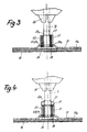
- the grinding or polishing plate according to the first embodiment consists of the platter 1 made of hard plastic, but in particular of steel with a grinding or polishing covering 2 applied with the interposition of a rubber plate 1a a, which for example by means of Velcro fastener is releasably attached.
- the cylindrical elastomer buffer 3 made of plastic or rubber is vulcanized here on the one hand at the plate connection to the mounting flange 4 with external thread 5 for applying a pot sleeve 6, the mounting flange 4 having a screw connection 7 for clamping the turntable 1 with a central bore 8 and lock nut 9, while on the other hand on the elastomer buffer 3 a flange 10 with clamping shaft 11 for connection to the drive chuck 12 is vulcanized.
- the pot sleeve 6 has at the open end an internal thread 13 matching the external thread 5 on the mounting flange 4 and has a bottom 14 at the other end with a central opening 15 for abutment against the flange 10 of the clamping shaft.
- the elastomer buffer 3 depending on the diameter of the turntable 1, has a much larger diameter than the clamping shaft 11, which leads to good stabilization and a long service life during grinding and polishing work even in the highest speed range.
- the turntable 1 can be flexibly applied for surface grinding and polishing without the sleeve 6, so that one-sided loop impressions are avoided. With the pot sleeve 6 attached, however, the turntable 1 is movable before tightening between limits, which also depend on the size of the central opening 15 in the base 14 and the diameter of the clamping shaft 11, and is rigidly connected to the drive chuck 12 after the sleeve 6 has been tightened, like this for a perfect edge grinding among other things is desired.
- the second exemplary embodiment shows a grinding and polishing plate likewise consisting of the platter 17 made of hard plastic, but in particular made of steel with a grinding or polishing covering 18 applied with the interposition of a rubber plate 17a, which, for example, by means of a Velcro fastener is releasably attached.
- the clamping shaft 19 for clamping in the drive chuck 20 is here surrounded at the other end by an elastomer buffer 21 made of plastic or rubber, namely the elastomer buffer 21 is vulcanized and surrounded with a metal sleeve 22, also vulcanized, which has an external thread 23 for the plate connection, on which the Turntable 17 is screwed on with its internal thread 24.
- a nut 25 can be screwed onto the thread 25a of the clamping shaft 19 against the sleeve 22 of the elastomer buffer 21.
- the clamping shaft 19 can, on the other hand, have an end flange 26 from the elastomer buffer 21 for mating with the sleeve 22.
- the flange 26 is reset so that it can be brought through the external thread 23 of the plate 17 and can be put on at the end of the sleeve 22 when the screw 25 is tightened.
- this can also be mounted from below, for which purpose the end flange 26 is screwed onto an end thread on the clamping shaft 19 and firmly glued.
- the vulcanized elastomer buffer 21 has an annular groove 27 or 28 on both ends for better tightening when fixed by means of a nut 25.
Landscapes
- Engineering & Computer Science (AREA)
- Mechanical Engineering (AREA)
- Polishing Bodies And Polishing Tools (AREA)
Priority Applications (1)
| Application Number | Priority Date | Filing Date | Title |
|---|---|---|---|
| AT85112958T ATE34932T1 (de) | 1984-10-26 | 1985-10-12 | Schleif- oder polierteller. |
Applications Claiming Priority (2)
| Application Number | Priority Date | Filing Date | Title |
|---|---|---|---|
| DE3439230A DE3439230C1 (de) | 1984-10-26 | 1984-10-26 | Schleif- oder Polierteller |
| DE3439230 | 1984-10-26 |
Publications (2)
| Publication Number | Publication Date |
|---|---|
| EP0180080A1 EP0180080A1 (de) | 1986-05-07 |
| EP0180080B1 true EP0180080B1 (de) | 1988-06-08 |
Family
ID=6248819
Family Applications (1)
| Application Number | Title | Priority Date | Filing Date |
|---|---|---|---|
| EP85112958A Expired EP0180080B1 (de) | 1984-10-26 | 1985-10-12 | Schleif- oder Polierteller |
Country Status (5)
| Country | Link |
|---|---|
| US (1) | US4674234A (es) |
| EP (1) | EP0180080B1 (es) |
| AT (1) | ATE34932T1 (es) |
| DE (2) | DE3439230C1 (es) |
| ES (2) | ES296347Y (es) |
Families Citing this family (14)
| Publication number | Priority date | Publication date | Assignee | Title |
|---|---|---|---|---|
| DE3705217C1 (de) * | 1986-09-17 | 1987-12-10 | Robert Wolff | Schleif- oder Polierteller |
| DE8716321U1 (de) * | 1987-12-10 | 1989-04-13 | Reiling, Karl, 7535 Königsbach-Stein | Schleif- oder Polierscheibe |
| GB8926883D0 (en) * | 1989-11-28 | 1990-01-17 | Lankry Julien J L | Attachment for a power tool |
| US5349786A (en) * | 1993-09-27 | 1994-09-27 | Dorrah James M | Apparatus and method for producing and oscillating, an orbiting and a vibrating movement on a disc body |
| US6322435B1 (en) * | 1998-01-28 | 2001-11-27 | Alan L. Hanosh | Rotary polishing discs and arbors therefor |
| GB2333981B (en) * | 1998-02-10 | 2000-05-03 | Brookdale Tool Co Ltd | A power tool attachment |
| DK200101806A (da) * | 2001-12-05 | 2003-06-06 | Nielsen Tom | Apparatur til brug ved fjernelse af et tapet |
| EP2425928A1 (de) * | 2010-09-06 | 2012-03-07 | WENDT GmbH | Flansch zur Montage eines Werkzeuges an einer Spindel |
| JP5343963B2 (ja) * | 2010-12-28 | 2013-11-13 | 日立工機株式会社 | 動力工具および先端工具 |
| CN203125128U (zh) * | 2012-11-14 | 2013-08-14 | 富鼎电子科技(嘉善)有限公司 | 毛刺去除装置 |
| CN203092275U (zh) * | 2012-12-19 | 2013-07-31 | 富鼎电子科技(嘉善)有限公司 | 打磨机构 |
| DE102013009129B4 (de) | 2013-05-31 | 2020-10-01 | Prime Supply Inc. | Verbesserte abrasive Vorrichtung |
| DE202013004950U1 (de) | 2013-05-31 | 2013-08-13 | Prime Supply Inc. | Verbesserte. abrasive Vorrichtung |
| DE202017004776U1 (de) | 2017-09-13 | 2017-10-10 | Prime Supply Inc. | Verbessertes Schleifwerkzeug |
Family Cites Families (13)
| Publication number | Priority date | Publication date | Assignee | Title |
|---|---|---|---|---|
| US2290011A (en) * | 1939-05-17 | 1942-07-14 | Casco Products Corp | Fan |
| US2269799A (en) * | 1939-09-23 | 1942-01-13 | Torrington Mfg Co | Fan hub and shaft assembly |
| US2371021A (en) * | 1944-07-25 | 1945-03-06 | Henry J Berry | Rotatable sanding or buffing tool |
| US2486078A (en) * | 1945-11-26 | 1949-10-25 | Flexentrik Co | Grinding machine |
| US2629990A (en) * | 1949-09-30 | 1953-03-03 | Berne Tocci Guilbert | Resilient coupling for abrasive wheels |
| US2666307A (en) * | 1952-07-02 | 1954-01-19 | William J Higert | Resilient coupling for grinding tools |
| US2767528A (en) * | 1953-12-29 | 1956-10-23 | Berne Tocci Guilbert | Back pad support |
| US2789402A (en) * | 1955-06-14 | 1957-04-23 | Berne Tocci Guilbert | Back pad |
| US3068664A (en) * | 1961-01-13 | 1962-12-18 | Tocci-Guilbert Berne | Resilient coupling |
| IT1145270B (it) * | 1979-07-09 | 1986-11-05 | Merit Abrasive Prod | Perfezionamento nej dischi abrasivi |
| DE3222858A1 (de) * | 1981-10-08 | 1983-05-05 | Karl 7539 Kämpfelbach Reiling | Schleif- oder polierscheibe |
| DE3301210C2 (de) * | 1983-01-15 | 1987-03-19 | Michail 5880 Lüdenscheid Pafilis | Spritzgießwerkzeug zum Herstellen eines Schleiftellers |
| US4479786A (en) * | 1983-03-07 | 1984-10-30 | The Torrington Company | Shaft assembly |
-
1984
- 1984-10-26 DE DE3439230A patent/DE3439230C1/de not_active Expired
-
1985
- 1985-10-12 EP EP85112958A patent/EP0180080B1/de not_active Expired
- 1985-10-12 AT AT85112958T patent/ATE34932T1/de not_active IP Right Cessation
- 1985-10-12 DE DE8585112958T patent/DE3563177D1/de not_active Expired
- 1985-10-22 US US06/790,191 patent/US4674234A/en not_active Expired - Fee Related
- 1985-10-25 ES ES1985296347U patent/ES296347Y/es not_active Expired
-
1987
- 1987-09-16 ES ES1987296854U patent/ES296854Y/es not_active Expired
Also Published As
| Publication number | Publication date |
|---|---|
| US4674234A (en) | 1987-06-23 |
| ES296347Y (es) | 1989-02-01 |
| DE3439230C1 (de) | 1986-02-27 |
| DE3563177D1 (en) | 1988-07-14 |
| ATE34932T1 (de) | 1988-06-15 |
| ES296854U (es) | 1988-02-01 |
| EP0180080A1 (de) | 1986-05-07 |
| ES296347U (es) | 1988-05-16 |
| ES296854Y (es) | 1988-09-16 |
Similar Documents
| Publication | Publication Date | Title |
|---|---|---|
| EP0180080B1 (de) | Schleif- oder Polierteller | |
| DE3012836A1 (de) | Vorrichtung zum festspannen der schleifscheibe von winkelschleifern | |
| DE19512991C2 (de) | Vorrichtung zum Befestigen eines Werkzeugs an einer Spindel eines Drehwerkzeuges | |
| DE4328987C1 (de) | Verwendung einer Schleifvorrichtung zum Feinschleifen von Kraftfahrzeugbremsen | |
| EP0319643B1 (de) | Schleif- oder Polierscheibe | |
| DE3917345A1 (de) | Einrichtung zum drehfesten vereinigen scheibenfoermiger bearbeitungswerkzeuge mit der arbeitsspindel von elektrowerkzeugen | |
| DE2156770A1 (de) | Vorrichtung zur loesbaren befestigung einer schleifscheibe oder dergleichen auf einer treibspindel | |
| EP0260422B1 (de) | Schleif- oder Polierteller | |
| DE593758C (de) | Schraubensicherung fuer Scheibenraeder | |
| DE3135820C2 (de) | Handschleifmaschine | |
| DE3410563C2 (de) | Spannvorrichtung für Werkzeuge od.dgl. | |
| DE2512438A1 (de) | Schnellverschluss zur loesbaren verbindung eines rotierenden werkzeuges, insbesondere eines schleifkoerpers mit einem tragkoerper | |
| DE4328985C2 (de) | Maschine zum Feinschleifen von vorbearbeiteten, ringscheibenförmigen metallischen Werkstücken | |
| DE2740574A1 (de) | Schleifteller fuer einen rotationsschleifer | |
| DE502659C (de) | Schraubensicherung | |
| DE1502612A1 (de) | Schnellbefestigungsvorrichtung fuer Einzelschleifkoerper bzw.-segmente | |
| DE817231C (de) | Drehbankfutter mit Spannbacken fuer Feinstbearbeitung | |
| DE10137625B4 (de) | Schnellspannmutter | |
| DE842764C (de) | Ventilschleifvorrichtung | |
| DE3601996C2 (es) | ||
| DE3222858A1 (de) | Schleif- oder polierscheibe | |
| DE2828470A1 (de) | Befestigungsvorrichtung fuer ein rad, insbesondere eines ackerschleppers, auf einer achse | |
| DE915881C (de) | Sicherungen fuer Schraubenmuttern, die ein selbsttaetiges Loesen verhindern | |
| CH716180B1 (de) | Vorrichtung und Verfahren zur mechanischen Finishbearbeitung einer Oberfläche eines Werkstückes. | |
| DE1932510U (de) | Schnellbefestigungsvorrichtung fuer einzelschliefkoerper bzw. -segmente. |
Legal Events
| Date | Code | Title | Description |
|---|---|---|---|
| PUAI | Public reference made under article 153(3) epc to a published international application that has entered the european phase |
Free format text: ORIGINAL CODE: 0009012 |
|
| AK | Designated contracting states |
Kind code of ref document: A1 Designated state(s): AT CH DE FR GB IT LI NL SE |
|
| 17P | Request for examination filed |
Effective date: 19860614 |
|
| 17Q | First examination report despatched |
Effective date: 19870220 |
|
| D17Q | First examination report despatched (deleted) | ||
| ITF | It: translation for a ep patent filed | ||
| GRAA | (expected) grant |
Free format text: ORIGINAL CODE: 0009210 |
|
| AK | Designated contracting states |
Kind code of ref document: B1 Designated state(s): AT CH DE FR GB IT LI NL SE |
|
| REF | Corresponds to: |
Ref document number: 34932 Country of ref document: AT Date of ref document: 19880615 Kind code of ref document: T |
|
| GBT | Gb: translation of ep patent filed (gb section 77(6)(a)/1977) | ||
| REF | Corresponds to: |
Ref document number: 3563177 Country of ref document: DE Date of ref document: 19880714 |
|
| ET | Fr: translation filed | ||
| PLBE | No opposition filed within time limit |
Free format text: ORIGINAL CODE: 0009261 |
|
| STAA | Information on the status of an ep patent application or granted ep patent |
Free format text: STATUS: NO OPPOSITION FILED WITHIN TIME LIMIT |
|
| 26N | No opposition filed | ||
| PGFP | Annual fee paid to national office [announced via postgrant information from national office to epo] |
Ref country code: DE Payment date: 19910821 Year of fee payment: 7 |
|
| PGFP | Annual fee paid to national office [announced via postgrant information from national office to epo] |
Ref country code: AT Payment date: 19910827 Year of fee payment: 7 |
|
| PGFP | Annual fee paid to national office [announced via postgrant information from national office to epo] |
Ref country code: FR Payment date: 19910828 Year of fee payment: 7 Ref country code: CH Payment date: 19910828 Year of fee payment: 7 |
|
| PGFP | Annual fee paid to national office [announced via postgrant information from national office to epo] |
Ref country code: SE Payment date: 19911014 Year of fee payment: 7 |
|
| ITTA | It: last paid annual fee | ||
| PGFP | Annual fee paid to national office [announced via postgrant information from national office to epo] |
Ref country code: NL Payment date: 19911031 Year of fee payment: 7 |
|
| PGFP | Annual fee paid to national office [announced via postgrant information from national office to epo] |
Ref country code: GB Payment date: 19911101 Year of fee payment: 7 |
|
| PG25 | Lapsed in a contracting state [announced via postgrant information from national office to epo] |
Ref country code: GB Effective date: 19921012 Ref country code: AT Effective date: 19921012 |
|
| PG25 | Lapsed in a contracting state [announced via postgrant information from national office to epo] |
Ref country code: SE Effective date: 19921013 |
|
| PG25 | Lapsed in a contracting state [announced via postgrant information from national office to epo] |
Ref country code: LI Effective date: 19921031 Ref country code: CH Effective date: 19921031 |
|
| PG25 | Lapsed in a contracting state [announced via postgrant information from national office to epo] |
Ref country code: NL Effective date: 19930501 |
|
| GBPC | Gb: european patent ceased through non-payment of renewal fee |
Effective date: 19921012 |
|
| NLV4 | Nl: lapsed or anulled due to non-payment of the annual fee | ||
| PG25 | Lapsed in a contracting state [announced via postgrant information from national office to epo] |
Ref country code: FR Effective date: 19930630 |
|
| REG | Reference to a national code |
Ref country code: CH Ref legal event code: PL |
|
| PG25 | Lapsed in a contracting state [announced via postgrant information from national office to epo] |
Ref country code: DE Effective date: 19930701 |
|
| REG | Reference to a national code |
Ref country code: FR Ref legal event code: ST |
|
| EUG | Se: european patent has lapsed |
Ref document number: 85112958.5 Effective date: 19930510 |