EP0175404B1 - Convertible head to form coils - Google Patents
Convertible head to form coils Download PDFInfo
- Publication number
- EP0175404B1 EP0175404B1 EP85201356A EP85201356A EP0175404B1 EP 0175404 B1 EP0175404 B1 EP 0175404B1 EP 85201356 A EP85201356 A EP 85201356A EP 85201356 A EP85201356 A EP 85201356A EP 0175404 B1 EP0175404 B1 EP 0175404B1
- Authority
- EP
- European Patent Office
- Prior art keywords
- coils
- rotor
- head
- coil
- rod
- Prior art date
- Legal status (The legal status is an assumption and is not a legal conclusion. Google has not performed a legal analysis and makes no representation as to the accuracy of the status listed.)
- Expired
Links
Images

Classifications
-
- B—PERFORMING OPERATIONS; TRANSPORTING
- B21—MECHANICAL METAL-WORKING WITHOUT ESSENTIALLY REMOVING MATERIAL; PUNCHING METAL
- B21C—MANUFACTURE OF METAL SHEETS, WIRE, RODS, TUBES, PROFILES OR LIKE SEMI-MANUFACTURED PRODUCTS OTHERWISE THAN BY ROLLING; AUXILIARY OPERATIONS USED IN CONNECTION WITH METAL-WORKING WITHOUT ESSENTIALLY REMOVING MATERIAL
- B21C47/00—Winding-up, coiling or winding-off metal wire, metal band or other flexible metal material characterised by features relevant to metal processing only
- B21C47/02—Winding-up or coiling
- B21C47/10—Winding-up or coiling by means of a moving guide
- B21C47/14—Winding-up or coiling by means of a moving guide by means of a rotating guide, e.g. laying the material around a stationary reel or drum
- B21C47/143—Winding-up or coiling by means of a moving guide by means of a rotating guide, e.g. laying the material around a stationary reel or drum the guide being a tube
-
- B—PERFORMING OPERATIONS; TRANSPORTING
- B21—MECHANICAL METAL-WORKING WITHOUT ESSENTIALLY REMOVING MATERIAL; PUNCHING METAL
- B21C—MANUFACTURE OF METAL SHEETS, WIRE, RODS, TUBES, PROFILES OR LIKE SEMI-MANUFACTURED PRODUCTS OTHERWISE THAN BY ROLLING; AUXILIARY OPERATIONS USED IN CONNECTION WITH METAL-WORKING WITHOUT ESSENTIALLY REMOVING MATERIAL
- B21C47/00—Winding-up, coiling or winding-off metal wire, metal band or other flexible metal material characterised by features relevant to metal processing only
- B21C47/26—Special arrangements with regard to simultaneous or subsequent treatment of the material
-
- B—PERFORMING OPERATIONS; TRANSPORTING
- B21—MECHANICAL METAL-WORKING WITHOUT ESSENTIALLY REMOVING MATERIAL; PUNCHING METAL
- B21C—MANUFACTURE OF METAL SHEETS, WIRE, RODS, TUBES, PROFILES OR LIKE SEMI-MANUFACTURED PRODUCTS OTHERWISE THAN BY ROLLING; AUXILIARY OPERATIONS USED IN CONNECTION WITH METAL-WORKING WITHOUT ESSENTIALLY REMOVING MATERIAL
- B21C47/00—Winding-up, coiling or winding-off metal wire, metal band or other flexible metal material characterised by features relevant to metal processing only
- B21C47/26—Special arrangements with regard to simultaneous or subsequent treatment of the material
- B21C47/262—Treatment of a wire, while in the form of overlapping non-concentric rings
Definitions
- This invention concerns a convertible head to form coils of rod delivered from a rolling unit and having different diameters.
- This head can be converted for use in forming coils arranged horizontally on a cooling conveyor or coils formed and positioned substantially vertically.
- the coil-forming head of the invention can be adapted for employment either with cooling conveyors able to carry coils arranged horizontally or with conveyors, chain or belt conveyors for instance, which can transport coils positioned vertically.
- cooling conveyors able to carry coils arranged horizontally or with conveyors, chain or belt conveyors for instance, which can transport coils positioned vertically.
- the coils are formed with the help of a drawing means that is a part of the rotor of the coil-forming head.
- the invention is intended in particular to obtain substantially vertical coils consisting of round bars of a large diameter (as an indication, from 12-15 mm to 30-35 mm or greater).
- Normal heads to form coils are known and various types of them already exist in the art; all of such heads comprise an inlet conduit for the rolled rod, which is perhaps guided by a drawing unit located upstream of the head, and also a rotary headstock or rotor. Such rotor is driven by suitable motor means and, as is known, forms the coils.
- the coils When formed, the coils fall onto a cooling conveyor and are transported thereon and undergo a controlled cooling at the same time.
- wound bundles are formed with such coils at the end of the conveyor line.
- a method for the formation of coils arranged vertically is also known.
- the coils are borne in succession along the cooling conveyors, being positioned vertically and substantially parallel to each other; in this case too the coils are gathered in wound bundles at the end of the cooling conveyor.
- patent GB-A-1,175,403 (SCHLOEMANN) is known and discloses a coil forming head of the "Edenborn" type with a horizontal axis.
- the coils in every case are formed vertically and always advance in a vertical position before being laid in a collecting vessel for the formation of bundles.
- the invention lies mainly in the fact that a worm thread is provided at the outlet of the tube laying the fili- form material and serves to form the individual coils.
- US-A-3,720,544 discloses the cooling treatment of coils of wire rod laid on a cooling conveyor.
- the coils are treated within an enclosure arranged appropriately so as to correspond with the controlled cooling conveyor.
- the coil forming headstock described diagrammatically, is of a stationary type and forms the coils in a vertical plane. The coils are then laid horizontally on the cooling conveyor in a known manner.
- US ⁇ A ⁇ 1,624,000 discloses a device equipped with a coil forming headstock having a vertical axis so as to lay horizontal coils on cores. Bundles are formed in this way and are removed from time to time by means of a rotary table or like means.
- Document DE-A-2,041,875 discloses a coil forming headstock which possesses the feature of being capable of being oriented about a horizontal axis so as to vary the inclination at which the coils are laid in order to correctly position the windings of the coils even with speeds of 60 m/sec or more.
- the orientation of the horizontal axis may range between 20° and 60° depending on the diameter of the deposited wire, the smaller being said diameter, the smaller being also the orientation angle.
- the headstock is preferably tiltable around an axis mounted on a fixed frame and may be clamped in different positions, in such a way as to be adaptable for different duty conditions.
- the headstock is not interchangeable.
- a first embodiment of this invention discloses a vessel to form bundles which is linked to a coil forming headstock coaxial with such vessel and having a vertical axis.
- the coils are formed horizontally and laid so as to form a bundle directly in the vessel.
- Forced draft cooling means are included.
- Another embodiment discloses an installation in which the coils are formed vertically by a coil forming headstock with a horizontal axis (Edenborn type). The coils move in a vertical position into a forced draft cooling tunnel and are then turned by 90° for collection in a cooling vessel which is not shown.
- the latter method of forming coils is particularly suitable for use with wire rod of a large diameter.
- the coil-forming head of the invention is convertible.
- two types of rotors can be fitted to the coil-forming head, one of them being suitable to form coils which fall, horizontally arranged, on the cooling conveyor, whereas the other type is suitable to form coils positioned substantially vertically and will be employed preferably with wire rod of large diameters.
- Such latter rotor for use with large diameters comprises also drawing means arranged peripherally, which have the purpose of imparting a drawing action to the rolled rod so as to enable it to be extracted from the coil-forming head itself.
- each type of rotor for vertical or horizontal coils respectively
- the coil-forming head is capable of being tilted.
- the coil-forming head In its horizontal position the coil-forming head will be suitable for arranging vertical coils with the help of the drawing means forming part of the type of rotor suited for use with large-diameter rod.
- the head When the head is tilted downwards, it can be used with the type of rotor for horizontal coils in the formation and immediate depositing of coils horizontally on the cooling conveyor. According to the invention the coil-forming head can cooperate with an initial tilted segment of the cooling conveyor when the coils have to be deposited horizontally.
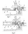
- a head 10 to form coils comprises a body 11, which is known in itself, together with a motor 12. The whole is positioned immediately downstream of a feeder unit 14 containing rollers to feed the rolled rod, which runs in the direction shown with an arrow.
- a rotor 15 for hoizonta I coils is fitted to the body 11 in the example of Fig. 1 and can be detached from the body 11, being coupled to the same in a known manner, for instance with a rapid coupling or screw coupling or a fixed joint or a coupling of another type.
- Fig. 1 shows coils 23 being deposited substantially horizontally.
- the coil-forming head 10 is tilted, being supported on a tiltable base 18 moved by actuator-means 19, which are of a known type such as jack means, screw-threaded means or another equivalent type known in the art.
- the actuator means 19 and tiltable base 18 and also the feeder unit 14 are supported by foundations 13 shown in the figure.
- the rotor 15 can possibly be arranged in cooperation with a protective screen 17 suitable for preventing any protrusion of the rod 26 outside the rotor 15.
- the cooling conveyor 20 shown comprises a first tiltable portion 120.
- the slope of this portion 120 is coordinated with the slope applied to the coil-forming head 10.
- Such slope can be about 5-6 0 or even more, whereas the tilting of the head 10 can vary from a minimum of 5-6 0 up to 12-15 0 so as to obtain the method of depositing coils 23 shown in the figure.
- drawing means, or drawing unit, 25 comprise rollers 27 able to exert on the rolled rod 26 a drawing action which accompanies the rotation of the rotor 16. It is possible in this way to obtain the feed and formation of coils 24 with rolled rod of a large diameter.
- large diameter we mean here a diameter ranging from 12-15 mm to 30-35 mm or more.
- the rotors 15-16 are interchangeable and have the same type of attachment for cooperation with the body 11 of the coil-forming head 10.
- two sets of rotors may be included, one set of two or more rotors for horizontal coils, such rotors being suitable for various diameters of rod, and one set of two or more rotors for vertical coils, such rotors too being suitable for various diameters of rod.
- the rotors 15-16 are equipped advantageously with eyelets or like attachments for handling with hooks, cables or chains of a crane or bridge crane, as shown with dotted lines in Figs. 1 and 2.
- Fig. 2 the coil-forming head 10 is shown cooperating with a conveyor or cooling conveyor belt 22 which comprises chains 122.
- Such chains 122 have the task of supporting and conveying the vertical coils 24 along the conveyor 22 according to a method known in the art.
- cooling hoods 121 which have a height sufficient to accommodate the vertically positioned coils 24; the working position of the coil-forming head 10 in this case is horizontal.
- Fig. 3 gives in greater detail a side view of a preferred embodiment of a rotor 16 of a type suitable to form vertical coils, preferably of rod of a large diameter.
- drawing rollers 27, which may be shaped suitably to engage the rolled rod 26 more securely, are sustained by supports 28, which in this example are solidly fixed to a bracket 29 of the rotor 16.
- Such supports 28 will be adjustable advantageously and preferably in a direction radial to the rotor 16 to suit the diameter of the coils which are to be obtained and possibly to suit the diameter of the rod 26.
- Fig. 3 means 30 to adjust the radial position of the rollers 27 are shown and are locking screw means in this case, but adjustment means of any equivalent type can be provided instead.
- rollers 27 are driven here through universal joints 31, which make possible such adjustment of the radial position of the supports 28 and therefore of the rollers 27.
- the universal joints 31 form the end of a motion-output unit 32, which rotates together with the rotor 16 and is driven by a motion take-off wheel 33.
- the latter get its motion by cooperating with a fixed toothed wheel 34 solidly fixed to the front portion of the body 11 of the coil-forming head 10.
- Fig. 3 also shows counterweights 35 which serve to counterbalance the masses corresponding to the drawing unit 25.
Landscapes
- Engineering & Computer Science (AREA)
- Mechanical Engineering (AREA)
- Winding, Rewinding, Material Storage Devices (AREA)
- Manufacture Of Motors, Generators (AREA)
- Magnetic Resonance Imaging Apparatus (AREA)
- Magnetic Heads (AREA)
- Superconductors And Manufacturing Methods Therefor (AREA)
- Coiling Of Filamentary Materials In General (AREA)
- Reciprocating, Oscillating Or Vibrating Motors (AREA)
- Headphones And Earphones (AREA)
- Turbine Rotor Nozzle Sealing (AREA)
Priority Applications (1)
| Application Number | Priority Date | Filing Date | Title |
|---|---|---|---|
| AT85201356T ATE39861T1 (de) | 1984-09-19 | 1985-08-27 | Umwandelbarer windungsleger. |
Applications Claiming Priority (2)
| Application Number | Priority Date | Filing Date | Title |
|---|---|---|---|
| IT6045984U | 1984-09-19 | ||
| ITUD1984U60459U IT8460459U1 (it) | 1984-09-19 | 1984-09-19 | Testa forma spire convertibile |
Publications (2)
| Publication Number | Publication Date |
|---|---|
| EP0175404A1 EP0175404A1 (en) | 1986-03-26 |
| EP0175404B1 true EP0175404B1 (en) | 1989-01-11 |
Family
ID=11291148
Family Applications (1)
| Application Number | Title | Priority Date | Filing Date |
|---|---|---|---|
| EP85201356A Expired EP0175404B1 (en) | 1984-09-19 | 1985-08-27 | Convertible head to form coils |
Country Status (6)
| Country | Link |
|---|---|
| US (1) | US4644773A (it) |
| EP (1) | EP0175404B1 (it) |
| AT (1) | ATE39861T1 (it) |
| DE (1) | DE3567388D1 (it) |
| ES (1) | ES8609492A1 (it) |
| IT (1) | IT8460459U1 (it) |
Families Citing this family (10)
| Publication number | Priority date | Publication date | Assignee | Title |
|---|---|---|---|---|
| JPH0829381B2 (ja) * | 1986-07-01 | 1996-03-27 | 株式会社モリタアンドカンパニー | コイルばね成形装置 |
| DE3940735A1 (de) * | 1989-12-09 | 1991-06-13 | Schloemann Siemag Ag | Kuehleinrichtung fuer walzdraht |
| DE4213459A1 (de) * | 1992-04-24 | 1993-10-28 | Schloemann Siemag Ag | Vorrichtung zum Transport von zu Ringen gewickeltem Walzgut im Haspelbereich |
| DE19725774A1 (de) * | 1997-06-18 | 1998-12-24 | Schloemann Siemag Ag | Vorrichtung zur Bildung von Schlingen aus einem aus einer Walzdrahtstraße austretenden Drahtstrang mittels eines rotierenden Schlingenlegers |
| DE19827349A1 (de) * | 1998-06-19 | 1999-12-23 | Schloemann Siemag Ag | Legekopf eines Windungslegers für Draht |
| DE19827348A1 (de) * | 1998-06-19 | 1999-12-23 | Schloemann Siemag Ag | Windungsleger für Draht |
| DE19853942C1 (de) * | 1998-11-24 | 2000-07-13 | Festo Ag & Co | Elektrischer Linearantrieb |
| US20080019805A1 (en) * | 2006-07-19 | 2008-01-24 | Bowler Martyn A | Method of transporting and heat treating coils of hot rolled products in a rolling mill |
| US8087604B2 (en) * | 2008-04-02 | 2012-01-03 | Siemens Industry, Inc. | Rolling mill pouring reel and its method of operation |
| CN102172647A (zh) * | 2011-01-27 | 2011-09-07 | 张家港长力机械有限公司 | 冷床输入辊道 |
Family Cites Families (13)
| Publication number | Priority date | Publication date | Assignee | Title |
|---|---|---|---|---|
| CA714947A (en) * | 1965-08-03 | Strand Thorleif | Apparatus for coiling wire or the like | |
| US429512A (en) * | 1890-06-03 | Machine for coiling wire | ||
| US1624000A (en) * | 1923-03-22 | 1927-04-12 | Cyclo Corp | Mechanism for and method of coiling wire or the like |
| DE1240025B (de) * | 1965-01-28 | 1967-05-11 | Schloemann Ag | Edenbornhaspel mit senkrechter oder waagerechter Drahtfuehrung |
| US3478408A (en) * | 1965-10-21 | 1969-11-18 | Kenard Daniel Brown | Method and apparatus for forming helical springs and the like |
| DE1452343A1 (de) * | 1965-10-23 | 1969-02-06 | Kocks Gmbh Friedrich | Vorrichtung zur Gefuegebehandlung von Walzdraht |
| DE1285435C2 (de) * | 1966-02-17 | 1973-10-04 | Schloemann Ag | Drehrohrhaspel zum ablegen von draht auf eine foerdereinrichtung |
| GB1175403A (en) * | 1967-02-09 | 1969-12-23 | Schloemann Ag | Edenborn Reel |
| AT303099B (de) * | 1969-03-05 | 1972-11-10 | Wendel Sidelor | Verfahren und Vorrichtungen zur Wärmebehandlung aus der Walzhitze eines Stahlwalzdrahtes mit weniger als 0,15% Kohlenstoff |
| DE2041875C3 (de) * | 1970-08-24 | 1975-07-17 | Fa. Friedrich Kocks, 4000 Duesseldorf | Führungsrohr, das einem Drehrohrhaspel für Draht nachgeordnet ist |
| DE2801010C2 (de) * | 1978-01-11 | 1980-01-24 | Rieter Deutschland Gmbh, 7000 Stuttgart | Drehteller zum Ablegen eines Faserbandes in eine Spinnkanne |
| JPS5941491B2 (ja) * | 1979-03-29 | 1984-10-08 | 株式会社神戸製鋼所 | 鋼線材の直接熱処理方法および装置 |
| DE2932729C2 (de) * | 1979-08-13 | 1987-08-20 | Kocks Technik GmbH & Co, 4000 Düsseldorf | Kühlstrecke zum Abkühlen von walzwarmem Draht |
-
1984
- 1984-09-19 IT ITUD1984U60459U patent/IT8460459U1/it unknown
-
1985
- 1985-08-27 AT AT85201356T patent/ATE39861T1/de not_active IP Right Cessation
- 1985-08-27 EP EP85201356A patent/EP0175404B1/en not_active Expired
- 1985-08-27 DE DE8585201356T patent/DE3567388D1/de not_active Expired
- 1985-09-04 US US06/772,480 patent/US4644773A/en not_active Expired - Fee Related
- 1985-09-10 ES ES546828A patent/ES8609492A1/es not_active Expired
Also Published As
| Publication number | Publication date |
|---|---|
| IT8460459U1 (it) | 1986-03-19 |
| DE3567388D1 (en) | 1989-02-16 |
| EP0175404A1 (en) | 1986-03-26 |
| ES546828A0 (es) | 1986-08-01 |
| ES8609492A1 (es) | 1986-08-01 |
| IT8460459V0 (it) | 1984-09-19 |
| ATE39861T1 (de) | 1989-01-15 |
| US4644773A (en) | 1987-02-24 |
Similar Documents
| Publication | Publication Date | Title |
|---|---|---|
| US4644773A (en) | Convertible head to form coils | |
| CN202346383U (zh) | 冷拔钢管自动分料输料装置 | |
| CA1115671A (en) | Coiling system for metallic strands | |
| EP1364726B1 (en) | Reinforcement cage making apparatus | |
| CA1110954A (en) | Wire accumulator tower | |
| EP0853058A3 (en) | Coiler apparatus and method | |
| JPS6018244A (ja) | 線材の直線切断方法およびその装置 | |
| US4310031A (en) | Apparatus for fanning out wire coils | |
| CN113073406B (zh) | 一种用于粗纱机的上料装置 | |
| CN106694602B (zh) | 不锈钢线加工设备 | |
| CN221581862U (zh) | 一种钢筋防护装置及具有该钢筋防护装置的钢筋调直设备 | |
| TWI357881B (en) | Apparatus and method for laying a tow | |
| CN113414325A (zh) | 一种预制桩的钢筋笼智能加工中心 | |
| CN1079302C (zh) | 供成形室里的线材环分布器用的安装结构 | |
| CN110950189B (zh) | 一种贵金属链的生产设备及其自动收链机 | |
| KR20000048097A (ko) | 와이어 로드 공급 장치 | |
| CN209954441U (zh) | 一种金属管抛光机自动进料设备 | |
| CN208408388U (zh) | 一种裁丝机工装 | |
| CN212525472U (zh) | 一种柔性扁平电缆生产设备用铜线上料架 | |
| CN223775692U (zh) | 高速线材轧制用吐丝装置 | |
| CN217432640U (zh) | 钢带送料姿态调节装置 | |
| CN111403108A (zh) | 一种漆包线的行线收紧装置 | |
| CN221806114U (zh) | 用于电池包线束的双头自动裁线打端子机 | |
| CN217676004U (zh) | 一种绕线机自动调节张力与自动送线收线机构 | |
| CN220217303U (zh) | 一种盘扣横杆焊接装置 |
Legal Events
| Date | Code | Title | Description |
|---|---|---|---|
| PUAI | Public reference made under article 153(3) epc to a published international application that has entered the european phase |
Free format text: ORIGINAL CODE: 0009012 |
|
| AK | Designated contracting states |
Kind code of ref document: A1 Designated state(s): AT BE CH DE FR GB LI LU NL SE |
|
| 17P | Request for examination filed |
Effective date: 19860908 |
|
| 17Q | First examination report despatched |
Effective date: 19871125 |
|
| GRAA | (expected) grant |
Free format text: ORIGINAL CODE: 0009210 |
|
| AK | Designated contracting states |
Kind code of ref document: B1 Designated state(s): AT BE CH DE FR GB LI LU NL SE |
|
| REF | Corresponds to: |
Ref document number: 39861 Country of ref document: AT Date of ref document: 19890115 Kind code of ref document: T |
|
| REF | Corresponds to: |
Ref document number: 3567388 Country of ref document: DE Date of ref document: 19890216 |
|
| ET | Fr: translation filed | ||
| PLBE | No opposition filed within time limit |
Free format text: ORIGINAL CODE: 0009261 |
|
| STAA | Information on the status of an ep patent application or granted ep patent |
Free format text: STATUS: NO OPPOSITION FILED WITHIN TIME LIMIT |
|
| 26N | No opposition filed | ||
| EPTA | Lu: last paid annual fee | ||
| EAL | Se: european patent in force in sweden |
Ref document number: 85201356.4 |
|
| PGFP | Annual fee paid to national office [announced via postgrant information from national office to epo] |
Ref country code: FR Payment date: 19970723 Year of fee payment: 13 Ref country code: CH Payment date: 19970723 Year of fee payment: 13 |
|
| PGFP | Annual fee paid to national office [announced via postgrant information from national office to epo] |
Ref country code: SE Payment date: 19970818 Year of fee payment: 13 |
|
| PGFP | Annual fee paid to national office [announced via postgrant information from national office to epo] |
Ref country code: GB Payment date: 19970820 Year of fee payment: 13 |
|
| PGFP | Annual fee paid to national office [announced via postgrant information from national office to epo] |
Ref country code: BE Payment date: 19970825 Year of fee payment: 13 |
|
| PGFP | Annual fee paid to national office [announced via postgrant information from national office to epo] |
Ref country code: AT Payment date: 19970828 Year of fee payment: 13 |
|
| PGFP | Annual fee paid to national office [announced via postgrant information from national office to epo] |
Ref country code: NL Payment date: 19970831 Year of fee payment: 13 |
|
| PGFP | Annual fee paid to national office [announced via postgrant information from national office to epo] |
Ref country code: LU Payment date: 19970910 Year of fee payment: 13 |
|
| PGFP | Annual fee paid to national office [announced via postgrant information from national office to epo] |
Ref country code: DE Payment date: 19970929 Year of fee payment: 13 |
|
| PG25 | Lapsed in a contracting state [announced via postgrant information from national office to epo] |
Ref country code: LU Free format text: LAPSE BECAUSE OF NON-PAYMENT OF DUE FEES Effective date: 19980827 Ref country code: GB Free format text: LAPSE BECAUSE OF NON-PAYMENT OF DUE FEES Effective date: 19980827 Ref country code: AT Free format text: LAPSE BECAUSE OF NON-PAYMENT OF DUE FEES Effective date: 19980827 |
|
| PG25 | Lapsed in a contracting state [announced via postgrant information from national office to epo] |
Ref country code: SE Free format text: LAPSE BECAUSE OF NON-PAYMENT OF DUE FEES Effective date: 19980828 |
|
| PG25 | Lapsed in a contracting state [announced via postgrant information from national office to epo] |
Ref country code: LI Free format text: LAPSE BECAUSE OF NON-PAYMENT OF DUE FEES Effective date: 19980831 Ref country code: CH Free format text: LAPSE BECAUSE OF NON-PAYMENT OF DUE FEES Effective date: 19980831 Ref country code: BE Free format text: LAPSE BECAUSE OF NON-PAYMENT OF DUE FEES Effective date: 19980831 |
|
| BERE | Be: lapsed |
Owner name: DANIELI & C. OFFICINE MECCANICHE S.P.A. Effective date: 19980831 |
|
| PG25 | Lapsed in a contracting state [announced via postgrant information from national office to epo] |
Ref country code: NL Free format text: LAPSE BECAUSE OF NON-PAYMENT OF DUE FEES Effective date: 19990301 |
|
| REG | Reference to a national code |
Ref country code: CH Ref legal event code: PL |
|
| GBPC | Gb: european patent ceased through non-payment of renewal fee |
Effective date: 19980827 |
|
| PG25 | Lapsed in a contracting state [announced via postgrant information from national office to epo] |
Ref country code: FR Free format text: LAPSE BECAUSE OF NON-PAYMENT OF DUE FEES Effective date: 19990430 |
|
| EUG | Se: european patent has lapsed |
Ref document number: 85201356.4 |
|
| NLV4 | Nl: lapsed or anulled due to non-payment of the annual fee |
Effective date: 19990301 |
|
| PG25 | Lapsed in a contracting state [announced via postgrant information from national office to epo] |
Ref country code: DE Free format text: LAPSE BECAUSE OF NON-PAYMENT OF DUE FEES Effective date: 19990601 |
|
| REG | Reference to a national code |
Ref country code: FR Ref legal event code: ST |