EP0166711A2 - Bauelement für einen Kachelofen - Google Patents
Bauelement für einen Kachelofen Download PDFInfo
- Publication number
- EP0166711A2 EP0166711A2 EP85890064A EP85890064A EP0166711A2 EP 0166711 A2 EP0166711 A2 EP 0166711A2 EP 85890064 A EP85890064 A EP 85890064A EP 85890064 A EP85890064 A EP 85890064A EP 0166711 A2 EP0166711 A2 EP 0166711A2
- Authority
- EP
- European Patent Office
- Prior art keywords
- tile
- projection
- tiles
- groove
- component according
- Prior art date
- Legal status (The legal status is an assumption and is not a legal conclusion. Google has not performed a legal analysis and makes no representation as to the accuracy of the status listed.)
- Granted
Links
Images

Classifications
-
- F—MECHANICAL ENGINEERING; LIGHTING; HEATING; WEAPONS; BLASTING
- F24—HEATING; RANGES; VENTILATING
- F24B—DOMESTIC STOVES OR RANGES FOR SOLID FUELS; IMPLEMENTS FOR USE IN CONNECTION WITH STOVES OR RANGES
- F24B1/00—Stoves or ranges
- F24B1/02—Closed stoves
- F24B1/04—Closed stoves built-up from glazed tiles
- F24B1/06—Construction of tiles or bracing means therefor, e.g. shim liner
-
- Y—GENERAL TAGGING OF NEW TECHNOLOGICAL DEVELOPMENTS; GENERAL TAGGING OF CROSS-SECTIONAL TECHNOLOGIES SPANNING OVER SEVERAL SECTIONS OF THE IPC; TECHNICAL SUBJECTS COVERED BY FORMER USPC CROSS-REFERENCE ART COLLECTIONS [XRACs] AND DIGESTS
- Y10—TECHNICAL SUBJECTS COVERED BY FORMER USPC
- Y10T—TECHNICAL SUBJECTS COVERED BY FORMER US CLASSIFICATION
- Y10T428/00—Stock material or miscellaneous articles
- Y10T428/16—Two dimensionally sectional layer
- Y10T428/163—Next to unitary web or sheet of equal or greater extent
- Y10T428/164—Continuous two dimensionally sectional layer
- Y10T428/166—Glass, ceramic, or metal sections [e.g., floor or wall tile, etc.]
-
- Y—GENERAL TAGGING OF NEW TECHNOLOGICAL DEVELOPMENTS; GENERAL TAGGING OF CROSS-SECTIONAL TECHNOLOGIES SPANNING OVER SEVERAL SECTIONS OF THE IPC; TECHNICAL SUBJECTS COVERED BY FORMER USPC CROSS-REFERENCE ART COLLECTIONS [XRACs] AND DIGESTS
- Y10—TECHNICAL SUBJECTS COVERED BY FORMER USPC
- Y10T—TECHNICAL SUBJECTS COVERED BY FORMER US CLASSIFICATION
- Y10T428/00—Stock material or miscellaneous articles
- Y10T428/17—Three or more coplanar interfitted sections with securing means
-
- Y—GENERAL TAGGING OF NEW TECHNOLOGICAL DEVELOPMENTS; GENERAL TAGGING OF CROSS-SECTIONAL TECHNOLOGIES SPANNING OVER SEVERAL SECTIONS OF THE IPC; TECHNICAL SUBJECTS COVERED BY FORMER USPC CROSS-REFERENCE ART COLLECTIONS [XRACs] AND DIGESTS
- Y10—TECHNICAL SUBJECTS COVERED BY FORMER USPC
- Y10T—TECHNICAL SUBJECTS COVERED BY FORMER US CLASSIFICATION
- Y10T428/00—Stock material or miscellaneous articles
- Y10T428/18—Longitudinally sectional layer of three or more sections
-
- Y—GENERAL TAGGING OF NEW TECHNOLOGICAL DEVELOPMENTS; GENERAL TAGGING OF CROSS-SECTIONAL TECHNOLOGIES SPANNING OVER SEVERAL SECTIONS OF THE IPC; TECHNICAL SUBJECTS COVERED BY FORMER USPC CROSS-REFERENCE ART COLLECTIONS [XRACs] AND DIGESTS
- Y10—TECHNICAL SUBJECTS COVERED BY FORMER USPC
- Y10T—TECHNICAL SUBJECTS COVERED BY FORMER US CLASSIFICATION
- Y10T428/00—Stock material or miscellaneous articles
- Y10T428/19—Sheets or webs edge spliced or joined
Definitions
- the invention relates to a component for a tiled stove, with a square tile and an associated, quadrangular, separate element made of refractory material, in particular chamotte, the tile having a tiled sheet and an adjoining tile body, which is relative to two opposite side edges has recessed surface sections to the circumference of the tile leaf, which merge into the projecting surface sections arranged on the side of the tile trunk facing away from the tile leaf, so that two adjacent tiles form a vertical groove lying between these surface sections, which, viewed in section, is normal to their longitudinal direction to expand the tile sheets, and in this groove the special element can be inserted, the side surfaces of which engage behind the projecting surface sections of the tiles.
- Tiled stoves are usually made with conventional stove ladles by placing them on mortar and filling the interstices with clay, mortar and brick pieces. The work required for this is very time-consuming, because two men need about eight hours to produce a square meter of tiled surface.
- tiled stoves without connecting compound.
- One proposal (AT-A 56 421) provides for the tiled body to be formed as two ribs which are bent symmetrically at an acute angle towards the center, as a result of which a dovetail-shaped groove is formed between the ribs of each tile, into which the ends of similar tile elements or in the same Tile trained bricks can be hooked in the manner of a toothing.
- a tile cladding for a stove has become known, in which a fitting piece is inserted at the joint between two adjacent tiles into a dovetail-shaped groove delimited by the two tiles.
- the purpose of this adapter is to form an adhesive surface for a plastering compound, with which the joints between adjacent tiles are filled. This filling of the butt joints between adjacent tiles is tedious and time-consuming, and what is more, with the construction according to the citation only the tile cladding, but not the inner structure of the tile stove carrying this cladding, can be produced.
- the invention has for its object to avoid the disadvantages of the known constructions and to provide a component for tiled stoves, with which not only the tiled layer of the tiled stove, but also its interior structure can be erected quickly, the labor-intensive placing of the tiles with mortar and the Filling in the gaps is at least largely eliminated. Furthermore, the invention sets itself the task of relieving the construction of tensile stresses, so that the components have a longer life than before.
- the invention solves this problem in that the separate element is formed by a plate arranged on the back of the tile body of the tile and carrying a projection engaging in the groove. Due to this special shape of the tiles and the separate elements assigned to them, the tile stove is manufactured in The plug-in method enables the use of mortar or the filling of gaps to be largely avoided.
- the components are free of tensile stresses, and the necessary cohesion of neighboring components can be achieved using conventional wire clips.
- Known asbestos cords or the like can be used to seal adjacent rows of tiles or coulters.
- Another advantage of the component according to the invention is that in a tiled stove which is produced using such components, the heat transfer from the combustion chamber or from the trains to the outside of the tile skin is faster than in the known constructions, since the insulating intermediate layer is made Pieces of clay and brick are missing.
- two layers namely those from the tile cladding of the furnace and those formed by the separate elements, are built together, which means a substantial saving in working time, especially since the tiles with the separate ones Elements are connected in such a way that this element pair cannot fall apart.
- the arrangement is such that the projection is arranged centrally on the plate, so that the plate overlaps half of two tiles adjacent to the projection.
- the bending stiffness can be increased by the fact that the projection completely fills the cross section of the groove.
- a particularly secure fit of the internal separate element on the tiles is achieved and an indentation or bulge of the tiled stove surface is made impossible.
- the projection is designed as a rib which runs over the height of the separate element, since in this way the same conditions are created in every height range of the separate element and the minimum cross-section of the projection thereby obtains a maximum length. It is therefore possible to form the groove and the projection in the form of a dovetail within the scope of the invention, which results in a particularly good interlocking leverage effect of the interacting components and also has the advantage that small manufacturing tolerances are automatically accommodated.
- the traction is effected by wire clips which can easily absorb the thermal stresses that occur.
- the arrangement is expediently such that the projection forms a support surface for a wire clip, which ends are anchored in the two tiles which form the groove receiving the projection.
- This contact surface for the wire clips facilitates the installation of the tile stove, since the wire clip is now securely supported by the projection and can therefore not accidentally fall out of its seat. It is hiebei according to the invention in an advantageous manner that each end of the wire clip rests against the inner wall of the tiled body formed as a frame, the lateral outer walls of the frame forming the projecting surface sections.
- This frame-like design or the recess enclosed by the frame lightens the weight of the tiles and at the same time anchoring them in a simple manner created for the Drart clips. Additional wire clips as well as sealing cords used to seal adjacent coulters can be accommodated in cavities which are formed in that the top wall and the bottom wall of the frame are set back against the edge of the tile sheet.
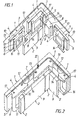
- Fig. 1 shows an exploded view of a portion of a family of a tile stove made of components according to the invention.
- Fig. 2 shows an oblique view of the elements in the assembled state.
- Fig. 3 is a view in the direction of arrow III of Fig. 2 and
- Fig. 4 is a view in the direction of arrow IV of Fig. 3 of a portion of the tile skin.
- the tiled stove is essentially made up of square tiles 1 and associated with them, also separate from the tiles 1, also square elements 2 made of chamotte.
- Each tile 1 has a tile sheet 3, on the inside of which a tile body 4 is integrally formed.
- the tiled trunk 4 has on the two opposite vertical side edges, relative to the circumference of the tiled sheet 3, recessed surface sections 5 which merge into the projecting surface sections 6 lying on the inside (that is, the side associated with the flue gas duct) of the tiled trunk 4.
- the surface sections 5, 6 of two adjacent tiles 1 delimit a groove 7 (FIG. 2) which runs with the same dovetail cross-section over the entire height of the tiles 1.
- the projection 8 is formed as a continuous rib over the entire height of the element 2 with a constant cross section, which is integral with a plate 9 of the element 2 ge is shaped.
- the height and width of the plate 9 and the entire element 2 are equal to the height of the tile sheet 3, the tile body 4, on the other hand, is somewhat set back against the circumference of the tile sheet 3 with its flat top wall 10 and its also flat bottom wall 11, so that on the horizontal Butt joints of adjacent tiles are cavities in the form of horizontally extending gaps, which serve to accommodate sealing cords 12 made of asbestos which ensure smoke tightness and to accommodate wire clips 13 which secure the traction of the tile structure.
- These bent clips 13 are inserted with their bent ends into holes 17 on the top wall 10 of the tile body 4 and each connect two adjacent tiles 1 to one another.
- wire clamps 14 which improve the traction of the tile association, are placed with their central part on the projections 8 of the elements 2 and snap with their bent ends into the tile body 4 designed as a frame, these wire clip ends resting against the inner walls 15 of the frame 16 and being secure there are anchored.
- the elements 2 in each family are offset somewhat downwards relative to the associated family of tiles 1 (FIG. 4), which at the same time increases the smoke tightness of the tiled stove wall.
- the tiles 1 per se can be cast or shaped in a known manner from a clay / chamotte mixture.
- the recessed surface sections 5 and the roof-like beveled surface sections 6 can be easily molded, as can the frame 16, the outer walls of which are at the same time projecting surface sections 6.
- the holes 17 can be easily punched during the manufacture of the tiles 1.
- the formation of the tiles 1 with a recessed or profiled tile sheet 3, for example as bowl tiles, is possible.
- the chamotte elements 2 can be pressed in the strand or in the shape.
- the drawings each show for a flat wall Part of the tile stove certain tiles 1 and a corner piece, which is formed from a normal tile 1 with a half-tile formed at a right angle.
- the construction principle of the cover piece is identical to the normal tiles 1.
- the tiles 1 When building the tiled stove wall, the tiles 1 are set up in droves and then the projections 8 of the elements 2 are pushed into the grooves 7 from above.
- the elements 2 overlap with their plates 9 each half of the tiles 1 on the inside, but are offset relative to the tiles 1 downward approximately by the width of the web of the frame 16 (FIG. 4).
- the remaining gaps on the corner tiles are filled with narrow firebrick strips.
- the wire clips 13 are inserted from above into the holes 17 and the wire clips 14 are placed on the upper sides of the projections 8 and their ends are inserted into the openings of the frames 16 of two adjacent plates.
- the connection of the tiles 1 is positive. Lateral escape is therefore impossible.
- the inner walls 15, which delimit the recess 18 of the frame 16, are normally on the front plane of the tile sheet 3, so that the inserted into these recesses 18, abutting the inner walls 15, right-angled end portions of the brackets 14 can not slide from the inner walls.
- the recesses 18 preferably have a square shape, possibly with rounded corners. They can be filled with fitted firebricks when installing the tiled stove.
- the tightness and the stability of the furnace can be further increased by an additional advance of fireclay panels, especially in the firebox and in the first few moves.
Applications Claiming Priority (2)
| Application Number | Priority Date | Filing Date | Title |
|---|---|---|---|
| AT0142684A AT387274B (de) | 1984-04-30 | 1984-04-30 | Bauelement fuer kacheloefen |
| AT1426/84 | 1984-04-30 |
Publications (3)
| Publication Number | Publication Date |
|---|---|
| EP0166711A2 true EP0166711A2 (de) | 1986-01-02 |
| EP0166711A3 EP0166711A3 (en) | 1987-04-15 |
| EP0166711B1 EP0166711B1 (de) | 1988-08-10 |
Family
ID=3513647
Family Applications (1)
| Application Number | Title | Priority Date | Filing Date |
|---|---|---|---|
| EP85890064A Expired EP0166711B1 (de) | 1984-04-30 | 1985-03-19 | Bauelement für einen Kachelofen |
Country Status (4)
| Country | Link |
|---|---|
| US (1) | US4675223A (ja) |
| EP (1) | EP0166711B1 (ja) |
| AT (1) | AT387274B (ja) |
| DE (1) | DE3564333D1 (ja) |
Cited By (3)
| Publication number | Priority date | Publication date | Assignee | Title |
|---|---|---|---|---|
| DE10028427A1 (de) * | 2000-06-13 | 2002-01-24 | Hermann Bichler | Quaderförmiger Baustein für eine Heizvorrichtung, insbesondere für einen Kachelofen oder dergleichen |
| AT409185B (de) * | 2000-03-09 | 2002-06-25 | Concept Kreative Prod | Feuerfester baustein |
| ITBO20090126A1 (it) * | 2009-03-04 | 2010-09-05 | Pavesi Srl | Perfezionamenti alla struttura del solaio orizzontale della copertura di un forno per la cottura di pizze o prodotti similari |
Families Citing this family (9)
| Publication number | Priority date | Publication date | Assignee | Title |
|---|---|---|---|---|
| US4857378A (en) * | 1988-06-03 | 1989-08-15 | Hayes Microcomputer Products, Inc. | Molded slanted front panel bezel for electronics enclosure |
| US4910063A (en) * | 1988-09-12 | 1990-03-20 | Maxadyne, Inc. | Insulating module |
| US5259758A (en) * | 1992-11-25 | 1993-11-09 | Wisconsin Oven Corporation | Industrial oven with expandable surfaces |
| DE19903999C2 (de) * | 1999-02-02 | 2002-06-13 | Josef Prax | Kachelofen |
| DE50111316D1 (de) * | 2001-08-28 | 2006-12-07 | Siemens Ag | Hitzeschildstein sowie Verwendung eines Hitzeschildsteins in einer Brennkammer |
| US7922959B2 (en) * | 2008-08-01 | 2011-04-12 | E. I. Du Pont De Nemours And Company | Method of manufacturing a composite filter media |
| US8291594B2 (en) * | 2008-08-01 | 2012-10-23 | The Boeing Company | Attachment system and method for thermal protection system |
| CN102677830B (zh) * | 2012-05-23 | 2014-05-07 | 上海品诚塑胶有限公司 | 易于组装和拆卸的插接板 |
| US11873762B2 (en) | 2020-06-16 | 2024-01-16 | Rolls-Royce Corporation | High temperature heat shield assemblies |
Citations (4)
| Publication number | Priority date | Publication date | Assignee | Title |
|---|---|---|---|---|
| CH96834A (de) * | 1921-07-21 | 1922-11-16 | Hollnecker Max | Kachelofen. |
| DE916579C (de) * | 1943-09-29 | 1954-08-12 | Egon Kortmann | Ofenkachelverband |
| DE920986C (de) * | 1944-03-16 | 1954-12-06 | Egon Kortmann | Ofenkachelverband |
| DE3150706A1 (de) * | 1981-12-22 | 1983-06-30 | Hans 7100 Heilbronn Zeidler | Kachelofen und vorrichtung sowie verfahren zum herstellen der kacheln |
Family Cites Families (2)
| Publication number | Priority date | Publication date | Assignee | Title |
|---|---|---|---|---|
| US1657453A (en) * | 1927-03-21 | 1928-01-31 | Liptak Fire Brick Arch Co | Furnace wall |
| AT257098B (de) * | 1964-05-29 | 1967-09-25 | Mosbacher Majolika Nerbel & Co | Kachelverkleidung für Öfen und Wände |
-
1984
- 1984-04-30 AT AT0142684A patent/AT387274B/de active
-
1985
- 1985-03-19 DE DE8585890064T patent/DE3564333D1/de not_active Expired
- 1985-03-19 EP EP85890064A patent/EP0166711B1/de not_active Expired
-
1986
- 1986-03-10 US US06/838,115 patent/US4675223A/en not_active Expired - Fee Related
Patent Citations (4)
| Publication number | Priority date | Publication date | Assignee | Title |
|---|---|---|---|---|
| CH96834A (de) * | 1921-07-21 | 1922-11-16 | Hollnecker Max | Kachelofen. |
| DE916579C (de) * | 1943-09-29 | 1954-08-12 | Egon Kortmann | Ofenkachelverband |
| DE920986C (de) * | 1944-03-16 | 1954-12-06 | Egon Kortmann | Ofenkachelverband |
| DE3150706A1 (de) * | 1981-12-22 | 1983-06-30 | Hans 7100 Heilbronn Zeidler | Kachelofen und vorrichtung sowie verfahren zum herstellen der kacheln |
Cited By (4)
| Publication number | Priority date | Publication date | Assignee | Title |
|---|---|---|---|---|
| AT409185B (de) * | 2000-03-09 | 2002-06-25 | Concept Kreative Prod | Feuerfester baustein |
| DE10028427A1 (de) * | 2000-06-13 | 2002-01-24 | Hermann Bichler | Quaderförmiger Baustein für eine Heizvorrichtung, insbesondere für einen Kachelofen oder dergleichen |
| DE10028427C2 (de) * | 2000-06-13 | 2002-07-18 | Hermann Bichler | Quaderförmiger Baustein für eine Heizvorrichtung, insbesondere für einen Kachelofen oder dergleichen |
| ITBO20090126A1 (it) * | 2009-03-04 | 2010-09-05 | Pavesi Srl | Perfezionamenti alla struttura del solaio orizzontale della copertura di un forno per la cottura di pizze o prodotti similari |
Also Published As
| Publication number | Publication date |
|---|---|
| AT387274B (de) | 1988-12-27 |
| DE3564333D1 (en) | 1988-09-15 |
| EP0166711A3 (en) | 1987-04-15 |
| US4675223A (en) | 1987-06-23 |
| EP0166711B1 (de) | 1988-08-10 |
| ATA142684A (de) | 1988-05-15 |
Similar Documents
| Publication | Publication Date | Title |
|---|---|---|
| DE2400954C2 (de) | Wandkonstruktion | |
| EP0166711B1 (de) | Bauelement für einen Kachelofen | |
| DE102007020494B4 (de) | Paneel zum Bau einer Wand oder einer Decke eines Bauwerks | |
| EP1571283A2 (de) | Verbinder von Abstandshalteprofilleisten zwischen Isolierglasscheiben | |
| DE10005426C2 (de) | Feuerfeste keramische Platte und zugehöriger Wandaufbau für einen Verbrennunsofen | |
| EP2960392A1 (de) | Deckenrandschalungselement | |
| DE2610998A1 (de) | Halterung zur befestigung von fassadenverkleidungsplatten | |
| EP0124855B1 (de) | Bauelement zur Erstellung von Grund- und Schutzbauten | |
| AT364501B (de) | Verkleidungselement, insbesondere wand- oder dachelement | |
| DE19519614C2 (de) | Kragplatten- und/oder Fugenelement für bewehrte Baukonstruktionen | |
| EP1767715A2 (de) | Glasbausteinwand | |
| EP2957685B1 (de) | Verbindung zwischen wandelementen | |
| EP0033485B1 (de) | Baustein zur Herstellung eines zweischaligen Kachelofens | |
| DE2815227A1 (de) | Wandelement sowie verfahren zur montage von wandelementen | |
| DE2163088A1 (de) | Pflanzkuebel | |
| EP1399627A1 (de) | Drainage-rinnenkörper, insbesondere aus polymerbeton | |
| DE2346687A1 (de) | Auskleidungselement und daraus hergestellte feuerfeste auskleidung | |
| AT386275B (de) | Ofenformstein oder kachel | |
| DE10028427C2 (de) | Quaderförmiger Baustein für eine Heizvorrichtung, insbesondere für einen Kachelofen oder dergleichen | |
| DE19729582B4 (de) | Formsteinsystem für eine Ofen-Ummauerung | |
| DE102004010524B4 (de) | Verbinder von Abstandshalteprofilleisten zwischen Isolierglasscheiben | |
| AT378398B (de) | Wand- oder deckenverkleidung | |
| DE19800712B4 (de) | Grundofen-Bausatz für einen Feuerraum | |
| DE2501323A1 (de) | Element zum verkleiden von aussenflaechen an gebaeuden | |
| DE1821291U (de) | Form- oder profilstueck fuer abwaesserkanaele aus keramischen massen. |
Legal Events
| Date | Code | Title | Description |
|---|---|---|---|
| PUAI | Public reference made under article 153(3) epc to a published international application that has entered the european phase |
Free format text: ORIGINAL CODE: 0009012 |
|
| AK | Designated contracting states |
Designated state(s): BE CH DE FR GB IT LI LU NL SE |
|
| PUAL | Search report despatched |
Free format text: ORIGINAL CODE: 0009013 |
|
| AK | Designated contracting states |
Kind code of ref document: A3 Designated state(s): BE CH DE FR GB IT LI LU NL SE |
|
| 17P | Request for examination filed |
Effective date: 19870320 |
|
| 17Q | First examination report despatched |
Effective date: 19870929 |
|
| GRAA | (expected) grant |
Free format text: ORIGINAL CODE: 0009210 |
|
| AK | Designated contracting states |
Kind code of ref document: B1 Designated state(s): BE CH DE FR GB IT LI LU NL SE |
|
| PG25 | Lapsed in a contracting state [announced via postgrant information from national office to epo] |
Ref country code: IT Free format text: LAPSE BECAUSE OF FAILURE TO SUBMIT A TRANSLATION OF THE DESCRIPTION OR TO PAY THE FEE WITHIN THE PRESCRIBED TIME-LIMIT;WARNING: LAPSES OF ITALIAN PATENTS WITH EFFECTIVE DATE BEFORE 2007 MAY HAVE OCCURRED AT ANY TIME BEFORE 2007. THE CORRECT EFFECTIVE DATE MAY BE DIFFERENT FROM THE ONE RECORDED. Effective date: 19880810 Ref country code: BE Effective date: 19880810 Ref country code: GB Free format text: LAPSE BECAUSE OF NON-PAYMENT OF DUE FEES Effective date: 19880810 Ref country code: FR Free format text: THE PATENT HAS BEEN ANNULLED BY A DECISION OF A NATIONAL AUTHORITY Effective date: 19880810 Ref country code: NL Effective date: 19880810 |
|
| REF | Corresponds to: |
Ref document number: 3564333 Country of ref document: DE Date of ref document: 19880915 |
|
| EN | Fr: translation not filed | ||
| NLV1 | Nl: lapsed or annulled due to failure to fulfill the requirements of art. 29p and 29m of the patents act | ||
| GBV | Gb: ep patent (uk) treated as always having been void in accordance with gb section 77(7)/1977 [no translation filed] | ||
| PG25 | Lapsed in a contracting state [announced via postgrant information from national office to epo] |
Ref country code: SE Effective date: 19890320 |
|
| PG25 | Lapsed in a contracting state [announced via postgrant information from national office to epo] |
Ref country code: LU Free format text: LAPSE BECAUSE OF NON-PAYMENT OF DUE FEES Effective date: 19890331 Ref country code: CH Effective date: 19890331 Ref country code: LI Effective date: 19890331 |
|
| PLBE | No opposition filed within time limit |
Free format text: ORIGINAL CODE: 0009261 |
|
| STAA | Information on the status of an ep patent application or granted ep patent |
Free format text: STATUS: NO OPPOSITION FILED WITHIN TIME LIMIT |
|
| 26N | No opposition filed | ||
| REG | Reference to a national code |
Ref country code: CH Ref legal event code: PL |
|
| PG25 | Lapsed in a contracting state [announced via postgrant information from national office to epo] |
Ref country code: DE Effective date: 19891201 |
|
| EUG | Se: european patent has lapsed |
Ref document number: 85890064.0 Effective date: 19900125 |