EP0166711A2 - Construction element for a tile stove - Google Patents
Construction element for a tile stove Download PDFInfo
- Publication number
- EP0166711A2 EP0166711A2 EP85890064A EP85890064A EP0166711A2 EP 0166711 A2 EP0166711 A2 EP 0166711A2 EP 85890064 A EP85890064 A EP 85890064A EP 85890064 A EP85890064 A EP 85890064A EP 0166711 A2 EP0166711 A2 EP 0166711A2
- Authority
- EP
- European Patent Office
- Prior art keywords
- tile
- projection
- tiles
- groove
- component according
- Prior art date
- Legal status (The legal status is an assumption and is not a legal conclusion. Google has not performed a legal analysis and makes no representation as to the accuracy of the status listed.)
- Granted
Links
Images

Classifications
-
- F—MECHANICAL ENGINEERING; LIGHTING; HEATING; WEAPONS; BLASTING
- F24—HEATING; RANGES; VENTILATING
- F24B—DOMESTIC STOVES OR RANGES FOR SOLID FUELS; IMPLEMENTS FOR USE IN CONNECTION WITH STOVES OR RANGES
- F24B1/00—Stoves or ranges
- F24B1/02—Closed stoves
- F24B1/04—Closed stoves built-up from glazed tiles
- F24B1/06—Construction of tiles or bracing means therefor, e.g. shim liner
-
- Y—GENERAL TAGGING OF NEW TECHNOLOGICAL DEVELOPMENTS; GENERAL TAGGING OF CROSS-SECTIONAL TECHNOLOGIES SPANNING OVER SEVERAL SECTIONS OF THE IPC; TECHNICAL SUBJECTS COVERED BY FORMER USPC CROSS-REFERENCE ART COLLECTIONS [XRACs] AND DIGESTS
- Y10—TECHNICAL SUBJECTS COVERED BY FORMER USPC
- Y10T—TECHNICAL SUBJECTS COVERED BY FORMER US CLASSIFICATION
- Y10T428/00—Stock material or miscellaneous articles
- Y10T428/16—Two dimensionally sectional layer
- Y10T428/163—Next to unitary web or sheet of equal or greater extent
- Y10T428/164—Continuous two dimensionally sectional layer
- Y10T428/166—Glass, ceramic, or metal sections [e.g., floor or wall tile, etc.]
-
- Y—GENERAL TAGGING OF NEW TECHNOLOGICAL DEVELOPMENTS; GENERAL TAGGING OF CROSS-SECTIONAL TECHNOLOGIES SPANNING OVER SEVERAL SECTIONS OF THE IPC; TECHNICAL SUBJECTS COVERED BY FORMER USPC CROSS-REFERENCE ART COLLECTIONS [XRACs] AND DIGESTS
- Y10—TECHNICAL SUBJECTS COVERED BY FORMER USPC
- Y10T—TECHNICAL SUBJECTS COVERED BY FORMER US CLASSIFICATION
- Y10T428/00—Stock material or miscellaneous articles
- Y10T428/17—Three or more coplanar interfitted sections with securing means
-
- Y—GENERAL TAGGING OF NEW TECHNOLOGICAL DEVELOPMENTS; GENERAL TAGGING OF CROSS-SECTIONAL TECHNOLOGIES SPANNING OVER SEVERAL SECTIONS OF THE IPC; TECHNICAL SUBJECTS COVERED BY FORMER USPC CROSS-REFERENCE ART COLLECTIONS [XRACs] AND DIGESTS
- Y10—TECHNICAL SUBJECTS COVERED BY FORMER USPC
- Y10T—TECHNICAL SUBJECTS COVERED BY FORMER US CLASSIFICATION
- Y10T428/00—Stock material or miscellaneous articles
- Y10T428/18—Longitudinally sectional layer of three or more sections
-
- Y—GENERAL TAGGING OF NEW TECHNOLOGICAL DEVELOPMENTS; GENERAL TAGGING OF CROSS-SECTIONAL TECHNOLOGIES SPANNING OVER SEVERAL SECTIONS OF THE IPC; TECHNICAL SUBJECTS COVERED BY FORMER USPC CROSS-REFERENCE ART COLLECTIONS [XRACs] AND DIGESTS
- Y10—TECHNICAL SUBJECTS COVERED BY FORMER USPC
- Y10T—TECHNICAL SUBJECTS COVERED BY FORMER US CLASSIFICATION
- Y10T428/00—Stock material or miscellaneous articles
- Y10T428/19—Sheets or webs edge spliced or joined
Definitions
- the invention relates to a component for a tiled stove, with a square tile and an associated, quadrangular, separate element made of refractory material, in particular chamotte, the tile having a tiled sheet and an adjoining tile body, which is relative to two opposite side edges has recessed surface sections to the circumference of the tile leaf, which merge into the projecting surface sections arranged on the side of the tile trunk facing away from the tile leaf, so that two adjacent tiles form a vertical groove lying between these surface sections, which, viewed in section, is normal to their longitudinal direction to expand the tile sheets, and in this groove the special element can be inserted, the side surfaces of which engage behind the projecting surface sections of the tiles.
- Tiled stoves are usually made with conventional stove ladles by placing them on mortar and filling the interstices with clay, mortar and brick pieces. The work required for this is very time-consuming, because two men need about eight hours to produce a square meter of tiled surface.
- tiled stoves without connecting compound.
- One proposal (AT-A 56 421) provides for the tiled body to be formed as two ribs which are bent symmetrically at an acute angle towards the center, as a result of which a dovetail-shaped groove is formed between the ribs of each tile, into which the ends of similar tile elements or in the same Tile trained bricks can be hooked in the manner of a toothing.
- a tile cladding for a stove has become known, in which a fitting piece is inserted at the joint between two adjacent tiles into a dovetail-shaped groove delimited by the two tiles.
- the purpose of this adapter is to form an adhesive surface for a plastering compound, with which the joints between adjacent tiles are filled. This filling of the butt joints between adjacent tiles is tedious and time-consuming, and what is more, with the construction according to the citation only the tile cladding, but not the inner structure of the tile stove carrying this cladding, can be produced.
- the invention has for its object to avoid the disadvantages of the known constructions and to provide a component for tiled stoves, with which not only the tiled layer of the tiled stove, but also its interior structure can be erected quickly, the labor-intensive placing of the tiles with mortar and the Filling in the gaps is at least largely eliminated. Furthermore, the invention sets itself the task of relieving the construction of tensile stresses, so that the components have a longer life than before.
- the invention solves this problem in that the separate element is formed by a plate arranged on the back of the tile body of the tile and carrying a projection engaging in the groove. Due to this special shape of the tiles and the separate elements assigned to them, the tile stove is manufactured in The plug-in method enables the use of mortar or the filling of gaps to be largely avoided.
- the components are free of tensile stresses, and the necessary cohesion of neighboring components can be achieved using conventional wire clips.
- Known asbestos cords or the like can be used to seal adjacent rows of tiles or coulters.
- Another advantage of the component according to the invention is that in a tiled stove which is produced using such components, the heat transfer from the combustion chamber or from the trains to the outside of the tile skin is faster than in the known constructions, since the insulating intermediate layer is made Pieces of clay and brick are missing.
- two layers namely those from the tile cladding of the furnace and those formed by the separate elements, are built together, which means a substantial saving in working time, especially since the tiles with the separate ones Elements are connected in such a way that this element pair cannot fall apart.
- the arrangement is such that the projection is arranged centrally on the plate, so that the plate overlaps half of two tiles adjacent to the projection.
- the bending stiffness can be increased by the fact that the projection completely fills the cross section of the groove.
- a particularly secure fit of the internal separate element on the tiles is achieved and an indentation or bulge of the tiled stove surface is made impossible.
- the projection is designed as a rib which runs over the height of the separate element, since in this way the same conditions are created in every height range of the separate element and the minimum cross-section of the projection thereby obtains a maximum length. It is therefore possible to form the groove and the projection in the form of a dovetail within the scope of the invention, which results in a particularly good interlocking leverage effect of the interacting components and also has the advantage that small manufacturing tolerances are automatically accommodated.
- the traction is effected by wire clips which can easily absorb the thermal stresses that occur.
- the arrangement is expediently such that the projection forms a support surface for a wire clip, which ends are anchored in the two tiles which form the groove receiving the projection.
- This contact surface for the wire clips facilitates the installation of the tile stove, since the wire clip is now securely supported by the projection and can therefore not accidentally fall out of its seat. It is hiebei according to the invention in an advantageous manner that each end of the wire clip rests against the inner wall of the tiled body formed as a frame, the lateral outer walls of the frame forming the projecting surface sections.
- This frame-like design or the recess enclosed by the frame lightens the weight of the tiles and at the same time anchoring them in a simple manner created for the Drart clips. Additional wire clips as well as sealing cords used to seal adjacent coulters can be accommodated in cavities which are formed in that the top wall and the bottom wall of the frame are set back against the edge of the tile sheet.
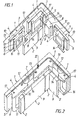
- Fig. 1 shows an exploded view of a portion of a family of a tile stove made of components according to the invention.
- Fig. 2 shows an oblique view of the elements in the assembled state.
- Fig. 3 is a view in the direction of arrow III of Fig. 2 and
- Fig. 4 is a view in the direction of arrow IV of Fig. 3 of a portion of the tile skin.
- the tiled stove is essentially made up of square tiles 1 and associated with them, also separate from the tiles 1, also square elements 2 made of chamotte.
- Each tile 1 has a tile sheet 3, on the inside of which a tile body 4 is integrally formed.
- the tiled trunk 4 has on the two opposite vertical side edges, relative to the circumference of the tiled sheet 3, recessed surface sections 5 which merge into the projecting surface sections 6 lying on the inside (that is, the side associated with the flue gas duct) of the tiled trunk 4.
- the surface sections 5, 6 of two adjacent tiles 1 delimit a groove 7 (FIG. 2) which runs with the same dovetail cross-section over the entire height of the tiles 1.
- the projection 8 is formed as a continuous rib over the entire height of the element 2 with a constant cross section, which is integral with a plate 9 of the element 2 ge is shaped.
- the height and width of the plate 9 and the entire element 2 are equal to the height of the tile sheet 3, the tile body 4, on the other hand, is somewhat set back against the circumference of the tile sheet 3 with its flat top wall 10 and its also flat bottom wall 11, so that on the horizontal Butt joints of adjacent tiles are cavities in the form of horizontally extending gaps, which serve to accommodate sealing cords 12 made of asbestos which ensure smoke tightness and to accommodate wire clips 13 which secure the traction of the tile structure.
- These bent clips 13 are inserted with their bent ends into holes 17 on the top wall 10 of the tile body 4 and each connect two adjacent tiles 1 to one another.
- wire clamps 14 which improve the traction of the tile association, are placed with their central part on the projections 8 of the elements 2 and snap with their bent ends into the tile body 4 designed as a frame, these wire clip ends resting against the inner walls 15 of the frame 16 and being secure there are anchored.
- the elements 2 in each family are offset somewhat downwards relative to the associated family of tiles 1 (FIG. 4), which at the same time increases the smoke tightness of the tiled stove wall.
- the tiles 1 per se can be cast or shaped in a known manner from a clay / chamotte mixture.
- the recessed surface sections 5 and the roof-like beveled surface sections 6 can be easily molded, as can the frame 16, the outer walls of which are at the same time projecting surface sections 6.
- the holes 17 can be easily punched during the manufacture of the tiles 1.
- the formation of the tiles 1 with a recessed or profiled tile sheet 3, for example as bowl tiles, is possible.
- the chamotte elements 2 can be pressed in the strand or in the shape.
- the drawings each show for a flat wall Part of the tile stove certain tiles 1 and a corner piece, which is formed from a normal tile 1 with a half-tile formed at a right angle.
- the construction principle of the cover piece is identical to the normal tiles 1.
- the tiles 1 When building the tiled stove wall, the tiles 1 are set up in droves and then the projections 8 of the elements 2 are pushed into the grooves 7 from above.
- the elements 2 overlap with their plates 9 each half of the tiles 1 on the inside, but are offset relative to the tiles 1 downward approximately by the width of the web of the frame 16 (FIG. 4).
- the remaining gaps on the corner tiles are filled with narrow firebrick strips.
- the wire clips 13 are inserted from above into the holes 17 and the wire clips 14 are placed on the upper sides of the projections 8 and their ends are inserted into the openings of the frames 16 of two adjacent plates.
- the connection of the tiles 1 is positive. Lateral escape is therefore impossible.
- the inner walls 15, which delimit the recess 18 of the frame 16, are normally on the front plane of the tile sheet 3, so that the inserted into these recesses 18, abutting the inner walls 15, right-angled end portions of the brackets 14 can not slide from the inner walls.
- the recesses 18 preferably have a square shape, possibly with rounded corners. They can be filled with fitted firebricks when installing the tiled stove.
- the tightness and the stability of the furnace can be further increased by an additional advance of fireclay panels, especially in the firebox and in the first few moves.
Abstract
Ein Bauelement für einen Kachelofen besteht aus einer viereckigen Kachel (1) und einem dieser zugeordneten, viereckigen, gesonderten Element (2). Die Kachel (1) besteht aus einem Kachelblatt (3), an das innenseitig ein Kachelrumpf (4) einstückig angeformt ist. Je zwei einander benachbarte Kacheln (1) begrenzen eine vertikale Nut (7), vorzugsweise mit Schwalbenschwanzquerschnitt, die von einem Vorsprung (8) des gesonderten Elements (2) ausgefüllt ist, das ansonsten als Platte (9) ausgebildet ist.A component for a tiled stove consists of a square tile (1) and a separate, square element (2) assigned to it. The tile (1) consists of a tile sheet (3), on the inside of which a tile body (4) is integrally formed. Two adjacent tiles (1) delimit a vertical groove (7), preferably with a dovetail cross section, which is filled by a projection (8) of the separate element (2), which is otherwise designed as a plate (9).
Description
Die Erfindung bezieht sich auf ein Bauelement für einen Kachelofen, mit einer viereckigen Kachel und einem dieser zugeordneten, viereckigen, gesonderten Element aus feuerfester Masse, insbesondere Schamotte, wobei die Kachel ein Kachelblatt und einen daran anschließenden Kachelrumpf hat, welcher an zwei einander gegenüberliegenden Seitenrändern relativ zum Umfang des Kachelblattes zurückspringende Flächenabschnitte hat, die in an der dem Kachelblatt abgewendeten Seite des Kachelrumpfes angeordnete, vorspringende Flächenabschnitte übergehen, so daß zwei einander benachbarte Kacheln eine zwischen diesen Flächenabschnitten liegende vertikale Nut bilden, die sich im Schnitt normal zu ihrer Längsrichtung gesehen, gegen die Kachelblätter zu erweitert, und wobei in diese Nut das gesondere Element einschiebbar ist, dessen Seitenflächen die vorspringenden Flächenabschnitte der Kacheln hintergreifen.The invention relates to a component for a tiled stove, with a square tile and an associated, quadrangular, separate element made of refractory material, in particular chamotte, the tile having a tiled sheet and an adjoining tile body, which is relative to two opposite side edges has recessed surface sections to the circumference of the tile leaf, which merge into the projecting surface sections arranged on the side of the tile trunk facing away from the tile leaf, so that two adjacent tiles form a vertical groove lying between these surface sections, which, viewed in section, is normal to their longitudinal direction to expand the tile sheets, and in this groove the special element can be inserted, the side surfaces of which engage behind the projecting surface sections of the tiles.
Kachelöfen werden zumeist mit herkömmlichen Ofenkadheln durch Versetzen derselben auf Mörtel und Ausfüllen der ZVi- schenräume mit Lehm, Mörtel und Ziegelstücken hergestellt. Die hiefür nötige Arbeit ist sehr zeitaufwendig, denn zwei Mann benötigen zur Herstellung eines Quadratmeters Kachelfläche, etwa acht Stunden.Tiled stoves are usually made with conventional stove ladles by placing them on mortar and filling the interstices with clay, mortar and brick pieces. The work required for this is very time-consuming, because two men need about eight hours to produce a square meter of tiled surface.
Man hat daher versucht, Kachelöfen ohne Verbindungsmasse herzustellen. Ein Vorschlag (AT-A 56 421) sieht vor, den Kachelrumpf als zwei symmetrisch unter einem spitzen Winkel gegen die Mitte zu gebogene Rippen auszubilden, wodurch zwischen den Rippen jeder Kachel eine schwalbenschwanzförmige Nut gebildet wird, in die die Enden gleichartiger Kachelelemente oder in gleicher Weise ausgebildete Ziegel nach Art einer Verzahnung eingehängt werden.Attempts have therefore been made to produce tiled stoves without connecting compound. One proposal (AT-A 56 421) provides for the tiled body to be formed as two ribs which are bent symmetrically at an acute angle towards the center, as a result of which a dovetail-shaped groove is formed between the ribs of each tile, into which the ends of similar tile elements or in the same Tile trained bricks can be hooked in the manner of a toothing.
Nachteilig hieran ist, daß insbesondere das innenliegende Element auf Zug belastet wird und daher bei Auftreten von Wärmedehnungsspannungen, die im Betrieb eines Kachelofens unvermeidlich sind, in erhöhter Weise belastet ist, so daß as bald zum Bruch der Kacheln und damit zu Undichtstellen im Kachelofen kommt. Außerdem ist es bei diesem bekannten System nicht möglich, die Kacheln vertieft als sogenannte Schüsselkacheln auszubilden.The disadvantage of this is that, in particular, the internal element is subjected to tension and is therefore subjected to increased stress when thermal expansion stresses occur, which are unavoidable in the operation of a tiled stove, so that the tiles soon break and thus lead to leaks in the tiled stove. In addition, it is not possible with this known system to design the tiles in a recessed manner as so-called bowl tiles.
Aus der AT-PS 257 098 ist eine Kachelverkleidung für einen Ofen bekanntgeworden, bei welcher an der Stoßstelle zwischen zwei benachbarten Kacheln in eine von den beiden Kacheln begrenzte schwalbenschwanzförmige Nut ein Paßstück eingeschoben ist. Zweck dieses Paßstückes ist es, eine Haftfläche für eine Putzmasse zu bilden, mit welcher die Fugen zwischen einander benachbarten Kacheln ausgefüllt werden. Dieses Ausfüllen der Stoßfugen zwischen einander benachbarten Kacheln ist mühsam und zeitraubend, wozu noch kommt, daß sich mit der Konstruktion nach der Entgegenhaltung lediglich die Kachelverkleidung, nicht aber der diese Verkleidung tragende Innenaufbau des Kachelofens herstellen läßt.From AT-PS 257 098 a tile cladding for a stove has become known, in which a fitting piece is inserted at the joint between two adjacent tiles into a dovetail-shaped groove delimited by the two tiles. The purpose of this adapter is to form an adhesive surface for a plastering compound, with which the joints between adjacent tiles are filled. This filling of the butt joints between adjacent tiles is tedious and time-consuming, and what is more, with the construction according to the citation only the tile cladding, but not the inner structure of the tile stove carrying this cladding, can be produced.
Die Erfindung setzt sich zur Aufgabe, die Nachteile der bekannten Konstruktionen zu vermeiden und ein Bauelement für Kachelöfen zu schaffen, mit welchem nicht nur die Kachelschicht des Kachelofens, sondern auch dessen Innenaufbau rasch errichtet werden kann, wobei das arbeitsaufwendige Versetzen der Kacheln mit Mörtel und das Ausfüllen der Zwischenräume zumindest zum Großteil entfällt. Weiters setzt sich die Erfindung zur Aufgabe, die Konstruktion von Zugspannungen zu entlasten, so daß die Bauelemente eine höhere Lebensdauer aufweisen als bisher.The invention has for its object to avoid the disadvantages of the known constructions and to provide a component for tiled stoves, with which not only the tiled layer of the tiled stove, but also its interior structure can be erected quickly, the labor-intensive placing of the tiles with mortar and the Filling in the gaps is at least largely eliminated. Furthermore, the invention sets itself the task of relieving the construction of tensile stresses, so that the components have a longer life than before.
Die Erfindung löst diese Aufgabe dadurch, daß das gesonderte Element von einer an der Rückseite des Kachelrumpfes der Kachel angeordneten Platte gebildet ist, die einen in die Nut eingreifenden Vorsprung trägt. Durch diese besondere Form der Kacheln und der ihnen zugeordneten gesonderten Elemente wird eine Herstellung des Kachelofens im Steckverfahren bei weitgehender Vermeidung einer Verwendung von Mörtel bzw. einer Ausfüllung von Zwischenräumen ermöglicht. Die Bauelemente sind hiebei von Zugspannungen frei, der nötige Zusammenhalt benachbarter Bauelemente kann durch herkömmliche Drahtklammern erfolgen. Zur Abdichtung benachbarter Kachelreihen bzw. Kachelscharen können an sich bekannte Asbestschnüre od. dgl. verwendet werden. Ein weiterer Vorteil des erfindungsgemäßen Bauelementes liegt darin, daß bei einem Kachelofen, der unter Verwendung solcher Bauelemente hergestellt ist, der Wärmetransport vom Feuerraum bzw. von den Zügen nach außen zur Kachelhaut rascher als bei den bekannten Konstruktionen vor sich geht, da die isolierende Zwischenschicht aus Lehm- und Ziegelstücken fehlt. Vor allem aber ist vorteilhaft, daß bei der Verlegung der erfindungsgemäßen Bauelemente zwei Schichten, nämlich jene aus der Kachelverkleidung des Ofens und jene, die von den gesonderten Elementen gebildet ist, zusammen errichtet werden, was eine wesentliche Arbeitszeitersparnis bedeutet, zumal die Kacheln mit den gesonderten Elementen so verbunden sind, daß diese Elementpaarung nicht auseinanderfallen kann. Dazu kommt, daß gegenüber der zuvor erwähnten bekannten Konstruktion das mühsame und zeitraubende Ausfüllen der Stoßfugen zwischen einander benachbarten Kacheln völlig entfällt, da die erfindungsgemäße Konstruktion es ermöglicht, den Kachelofen im Steckverfahren bei weitgehender Vermeidung einer Verwendung von Mörtel bzw. einer Ausfüllung von Zwischenräumen herzustellen, wobei diese Bauweise sowohl im Bereiche des Feuerraumes als auch im Bereich der den Rauch führenden Züge anwendbar ist.The invention solves this problem in that the separate element is formed by a plate arranged on the back of the tile body of the tile and carrying a projection engaging in the groove. Due to this special shape of the tiles and the separate elements assigned to them, the tile stove is manufactured in The plug-in method enables the use of mortar or the filling of gaps to be largely avoided. The components are free of tensile stresses, and the necessary cohesion of neighboring components can be achieved using conventional wire clips. Known asbestos cords or the like can be used to seal adjacent rows of tiles or coulters. Another advantage of the component according to the invention is that in a tiled stove which is produced using such components, the heat transfer from the combustion chamber or from the trains to the outside of the tile skin is faster than in the known constructions, since the insulating intermediate layer is made Pieces of clay and brick are missing. Above all, however, it is advantageous that when laying the components according to the invention, two layers, namely those from the tile cladding of the furnace and those formed by the separate elements, are built together, which means a substantial saving in working time, especially since the tiles with the separate ones Elements are connected in such a way that this element pair cannot fall apart. In addition, the laborious and time-consuming filling of the butt joints between adjacent tiles is completely eliminated compared to the known construction mentioned above, since the construction according to the invention makes it possible to manufacture the tiled stove using the plug-in method while largely avoiding the use of mortar or filling gaps, this design can be used both in the area of the combustion chamber and in the area of the trains carrying the smoke.
Gemäß einer Weiterbildung der Erfindung ist die Anordnung so getroffen, daß der Vorsprung mittig an der Platte angeordnet ist, so daß die Platte zwei dem Vorsprung benachbarte Kacheln je zur Hälfte übergreift. Dadurch bilden die erfindungsgemäßen Kacheln zusammen mit den mit ihnen verbundenen, vorzugsweise aus Schamotte bestehenden, gesonderten Elementen einen im wesentlichen biegesteifen Verband, dessen Biegesteifigkeit noch dadurch erhöht werden kann, daß der Vorsprung den Querschnitt der Nut voll ausfüllt. Außerdem wird dadurch ein besonders sicherer Sitz des innenliegenden gesonderten Elementes an den Kacheln erzielt und eine Ein- oder Ausbuchtung der Kachelofenoberfläche unmöglich gemacht. Besonders günstig ist es erfindungsgemäß, wenn der Vorsprung als Rippe ausgebildet ist, die über die Höhe des gesonderten Elementes durchläuft, da auf diese Weise in jedem Höhenbereich des gesonderten Elementes gleiche Verhältnisse geschaffen sind und der Mindestquerschnitt des Vorsprunges dadurch eine maximale Länge erhält. Es wird daher möglich, im Rahmen der Erfindung die Nut und den Vorsprung schwalbenschwanzförmig auszubilden, was eine besonders gut ineinandergreifende Hebelwirkung der miteinander zusammenwirkenden Bauteile ergibt und weiters den Vorteil hat, daß geringe Herstellungstoleranzen automatisch aufgenommen werden.According to a development of the invention, the arrangement is such that the projection is arranged centrally on the plate, so that the plate overlaps half of two tiles adjacent to the projection. As a result, the tiles according to the invention, together with the separate elements connected to them, preferably consisting of fireclay, form an essentially rigid connection. the bending stiffness can be increased by the fact that the projection completely fills the cross section of the groove. In addition, a particularly secure fit of the internal separate element on the tiles is achieved and an indentation or bulge of the tiled stove surface is made impossible. It is particularly advantageous according to the invention if the projection is designed as a rib which runs over the height of the separate element, since in this way the same conditions are created in every height range of the separate element and the minimum cross-section of the projection thereby obtains a maximum length. It is therefore possible to form the groove and the projection in the form of a dovetail within the scope of the invention, which results in a particularly good interlocking leverage effect of the interacting components and also has the advantage that small manufacturing tolerances are automatically accommodated.
Wie bereits erwähnt, wird bei der erfindungsgemäßen Konstruktion die Zugschlüssigkeit durch Drahtklammern bewirkt, welche die auftretenden Wärmebeanspruchungen ohne weiteres aufnehmen können. Im Rahmen der Erfindung ist zweckmäßig die Anordnung so getroffen, daß der Vorsprung eine Auflagefläche für eine Drahtklammer bildet, die mit ihren Enden in den beiden Kacheln verankert ist, welche die den Vorsprung aufnehmende Nut bilden. Diese Auflagefläche für die Drahtklammern erleichtert die Montage des Kachelofens, da nunmehr die Drahtklammer durch den Vorsprung sicher abgestützt ist und daher nicht unbeabsichtigt aus ihrem Sitz herausfallen kann. Es ist hiebei erfindungsgemäß in vorteilhafter Weise die Anordnung so getroffen, daß jedes Ende der Drahtklammer an der Innenwand des als Rahmen ausgebildeten Kachelrumpfes anliegt, wobei die seitlichen Außenwände des Rahmens die vorspringenden Flächenabschnitte bilden. Durch diese rahmenartige Ausbildung bzw. durch die vom Rahmen umschlossene Ausnehmung wird das Gewicht der Kacheln erleichtert und zugleich auf einfache Weise eine Verankerung für die Drartklammern geschaffen. Zusätzliche Drahtklammern sowie zur Abdichtung benachbarter Scharen dienende Dichtungsschnüre können in Hohlräumen untergebracht sein, welche dadurch gebildet sind, daß die Deckwand und die Bodenwand des Rahmens gegen den Rand des Kachelblattes zurückversetzt sind.As already mentioned, in the construction according to the invention, the traction is effected by wire clips which can easily absorb the thermal stresses that occur. In the context of the invention, the arrangement is expediently such that the projection forms a support surface for a wire clip, which ends are anchored in the two tiles which form the groove receiving the projection. This contact surface for the wire clips facilitates the installation of the tile stove, since the wire clip is now securely supported by the projection and can therefore not accidentally fall out of its seat. It is hiebei according to the invention in an advantageous manner that each end of the wire clip rests against the inner wall of the tiled body formed as a frame, the lateral outer walls of the frame forming the projecting surface sections. This frame-like design or the recess enclosed by the frame lightens the weight of the tiles and at the same time anchoring them in a simple manner created for the Drart clips. Additional wire clips as well as sealing cords used to seal adjacent coulters can be accommodated in cavities which are formed in that the top wall and the bottom wall of the frame are set back against the edge of the tile sheet.
In der Zeichnung ist ein Ausführungsbeispiel der Erfindung schematisch dargestellt. Fig. 1 zeigt eine Explosionsansicht eines Abschnittes einer Schar eines aus erfindungsgemäßen Bauelementen hergestellten Kachelofens.In the drawing, an embodiment of the invention is shown schematically. Fig. 1 shows an exploded view of a portion of a family of a tile stove made of components according to the invention.
Fig. 2 zeigt in Schrägansicht die Elemente im zusammengefügten Zustand. Fig. 3 ist eine Ansicht in Richtung des Pfeiles III der Fig. 2 und Fig. 4 ist eine Ansicht in Richtung des Pfeiles IV der Fig. 3 auf einen Abschnitt der Kachelhaut.Fig. 2 shows an oblique view of the elements in the assembled state. Fig. 3 is a view in the direction of arrow III of Fig. 2 and Fig. 4 is a view in the direction of arrow IV of Fig. 3 of a portion of the tile skin.
Der Kachelofen wird im wesentlichen aus viereckigen Kacheln 1 und diesen zugeordneten, von den Kacheln 1 gesonderten, ebenfalls viereckigen Elementen 2 aus Schamotte aufgebaut. Jede Kachel 1 hat ein Kachelblatt 3, an das innenseitig ein Kachelrumpf 4 einstückig angeformt ist. Der Kachelrumpf 4 hat an den beiden einander gegenüberliegenden vertikalen Seitenrändern relativ zum Umfang des Kachelblattes 3 zurückspringende Flächenabschnitte 5, welche in an der Innenseite (das ist die dem Rauchgaszug zugeordnete Seite) des Kachelrumpfes 4 liegende, vorspringende Flächenabschnitte 6 übergehen. Die Flächenabschnitte 5, 6 zweier benachbarter Kacheln 1 begrenzen eine Nut 7 (Fig. 2), die mit gleichbleibendem schwalbenschwanzförmigen Querschnitt über die gesamte Höhe der Kacheln 1 durchläuft. In diese Nut 7 ist ein ebenfalls mit schwalbenschwanzförmigem Querschnitt ausgebildeter Vorsprung 8 des Elementes 2 passend einschiebbar, wobei im eingeschobenen Zustand dieser Vorsprung 8 die ihn aufnehmende Nut 7 im wesentlichen voll ausfüllt. Der Vorsprung 8 ist als über die gesamte Höhe des Elementes 2 mit gleichbleibendem Querschnitt durchlaufende Rippe ausgebildet, die einstückig mit einer Platte 9 des Elementes 2 geformt ist. Die Höhe und Breite der Platte 9 und des gesamten Elementes 2 sind gleich der Höhe des Kachelblattes 3, der Kachelrumpf 4 liegt hingegen mit seiner ebenen Deckwand 10 und seiner ebenfalls ebenen Bodenwand 11 etwas gegen den Umfang des Kachelblattes 3 zurückversetzt, so daß an den horizontalen Stoßstellen benachbarter Kachelscharen Hohlräume in Form horizontal verlaufender Spalte gebildet werden, die zur Aufnahme von die Rauchdichtheit sichernden Dichtungsschnüren 12 aus Asbest sowie zur Aufnahme von die Zugschlüssigkeit des Kachelverbandes sichernden Drahtklammern 13 dienen. Diese Drahtklammern 13 sind mit ihren abgebogenen Enden in Löcher 17 an der Deckwand 10 des Kachelrumpfes 4 eingesteckt und verbinden jeweils zwei benachbarte Kacheln 1 miteinander. Weitere, die Zugschlüssigkeit des Kachelverbandes verbessernde Drahtklammern 14 sind mit ihrem Mittelteil auf die Vorsprünge 8 der Elemente 2 aufgelegt und rasten mit ihren abgebogenen Enden in den als Rahmen ausgebildeten Kachelrumpf 4 ein, wobei diese Drahtklammernenden an den Innenwänden 15 des Rahmens 16 anliegen und dort sicher verankert sind. Um dies zu ermöglichen, sind in jeder Schar die Elemente 2 etwas nach unten gegenüber der zugehörigen Schar der Kacheln 1 versetzt (Fig. 4), was zugleich die Rauchdichtheit der Kachelofenwand erhöht.The tiled stove is essentially made up of
Die Kacheln 1 für sich können in bekannter WI" ise aus einem Ton-Schamotte-Gemisch gegossen oder geformt sein. Dabei lassen sich die zurückspringenden Flächenabschnitte 5 und die dachartig abgeschrägt vorspringenden Flächenabschnitte 6 leicht mitformen, ebenso wie der Rahmen 16, dessen Außenwände zugleich die vorspringenden Flächenabschnitte 6 bilden. Die Löcher 17 lassen sich bei der Herstellung der Kacheln 1 leicht einstanzen. Die Ausbildung der Kacheln 1 mit vertieft bzw. profiliert ausgebildetem Kachelblatt 3, z.B. als Schüsselkacheln, ist möglich. Die Schamotteelemente 2 können durch Pressen im Strang oder in der Form hergestellt werden.The
Die Zeichnungen zeigen jeweils für einen ebenen Wandteil des Kachelofens bestimmte Kacheln 1 sowie ein Eckstück, welches aus einer normalen Kachel 1 mit im rechten Winkel angeformter Halbkachel gebildet ist. Das Aufbauprinzip des Deckstückes ist mit den normalen Kacheln 1 identisch. Hinter dem Eckstück liegt ein mit verkürzter Breite ausgebildetes Element 2, dessen Aufbauprinzip ansonsten jenem der normalen Elemente 2 gleich ist, nur ist beim verkürzt ausgebildeten Element 2 der Vorsprung 8 etwa gleich breit wie die Platte 9.The drawings each show for a flat wall Part of the tile stove
Beim Aufbau der Kachelofenwand werden die Kacheln 1 scharenweise aufgestellt und in die Nuten 7 sodann die Vorsprünge 8 der Elemente 2 von oben eingeschoben. Die Elemente 2 übergreifen hiebei mit ihren Platten 9 die Kacheln 1 an ihrer Innenseite je zur Hälfte, sind jedoch gegenüber den Kacheln 1 nach unten etwa um die Breite des Steges des Rahmens 16 versetzt (Fig. 4). Die verbleibenden Spalte an den Eckkacheln werden durch schmäler ausgebildete Schamottestreifen ausgefüllt. Sodann werden die Drahtklammern 13 von oben in die Löcher 17 eingesteckt und die Drahtklammern 14 auf die Oberseiten der Vorsprünge 8 aufgelegt und mit ihren Enden in die Öffnungen der Rahmen 16 je zweier benachbarter Platten eingeschoben. Dadurch wird die Verbindung der Kacheln 1 zugschlüssig. Ein seitliches Entweichen ist daher unmöglich. Auch ein Aus- oder Einbuchten ist durch das Ineinandergreifen bzw. die damit verbundene Hebelwirkung der schwalbenschwanzförmigen Querschnitte der Nut 7 bzw. des Vorsprunges 8 nicht möglich. Nach Einlegen von Dichtungsschnüren 12 in den von der zurückgesetzten Deckfläche 10 des Kachelrumpfes 4 gebildeten Hohlraum, gegebenenfalls auch auf die Deckfläche der Elemente 2, kann die nächste Schar der Kacheln 1 bzw. der Elemente 2 aufgesetzt werden. Durch das bausteinartige System ist jede äußere Form sowie auch der Einbau jedweder Innenkonstruktion nach Bedarf möglich.When building the tiled stove wall, the
Die Innenwände 15, welche die Aussparung 18 des Rahmens 16 begrenzen, stehen normal auf die Frontebene des Kachelblattes 3, so daß die in diese Aussparungen 18 eingesetzten, an den Innenwänden 15 anliegenden, rechtwinkelig abgewinkelten Endteile der Klammern 14 nicht von den Innenwänden abgleiten können.The
Die Aussparungen 18 haben vorzugsweise viereckige Form, gegebenenfalls mit ausgerundeten Ecken. Sie können bei der Errichtung des Kachelofens mit eingepaßten Schamottesteinen ausgefüllt werden.The recesses 18 preferably have a square shape, possibly with rounded corners. They can be filled with fitted firebricks when installing the tiled stove.
Zur Erhöhung der Rauchdichtheit können zusätzlich zu den zweckmäßig aus Asbest bestehenden Dichtungsschnüren 12 noch an sich bekannte elastische Verfugungen Verwendung finden, so daß die gesamte Konstruktion dehnungsfähig bleibt und die im Betrieb auftretenden Wärmespannungen gut aufnehmen kann.In order to increase smoke tightness, in addition to the
Die Dichtheit sowie die Stabilität des Ofens kann weiter dadurch gesteigert werden, daß ein zusätzlicher Vorschub von Schamotteplatten erfolgt, insbesondere im Feuerraum und in den ersten Zügen.The tightness and the stability of the furnace can be further increased by an additional advance of fireclay panels, especially in the firebox and in the first few moves.
Claims (7)
Applications Claiming Priority (2)
| Application Number | Priority Date | Filing Date | Title |
|---|---|---|---|
| AT0142684A AT387274B (en) | 1984-04-30 | 1984-04-30 | COMPONENT FOR TILE STOVES |
| AT1426/84 | 1984-04-30 |
Publications (3)
| Publication Number | Publication Date |
|---|---|
| EP0166711A2 true EP0166711A2 (en) | 1986-01-02 |
| EP0166711A3 EP0166711A3 (en) | 1987-04-15 |
| EP0166711B1 EP0166711B1 (en) | 1988-08-10 |
Family
ID=3513647
Family Applications (1)
| Application Number | Title | Priority Date | Filing Date |
|---|---|---|---|
| EP85890064A Expired EP0166711B1 (en) | 1984-04-30 | 1985-03-19 | Construction element for a tile stove |
Country Status (4)
| Country | Link |
|---|---|
| US (1) | US4675223A (en) |
| EP (1) | EP0166711B1 (en) |
| AT (1) | AT387274B (en) |
| DE (1) | DE3564333D1 (en) |
Cited By (3)
| Publication number | Priority date | Publication date | Assignee | Title |
|---|---|---|---|---|
| DE10028427A1 (en) * | 2000-06-13 | 2002-01-24 | Hermann Bichler | Rectangular block for a heating device, in particular for a tiled stove or the like |
| AT409185B (en) * | 2000-03-09 | 2002-06-25 | Concept Kreative Prod | Refractory building block |
| ITBO20090126A1 (en) * | 2009-03-04 | 2010-09-05 | Pavesi Srl | IMPROVEMENT OF THE STRUCTURE OF THE HORIZONTAL FLOOR OF A OVEN COVER FOR COOKING PIZZAS OR SIMILAR PRODUCTS |
Families Citing this family (9)
| Publication number | Priority date | Publication date | Assignee | Title |
|---|---|---|---|---|
| US4857378A (en) * | 1988-06-03 | 1989-08-15 | Hayes Microcomputer Products, Inc. | Molded slanted front panel bezel for electronics enclosure |
| US4910063A (en) * | 1988-09-12 | 1990-03-20 | Maxadyne, Inc. | Insulating module |
| US5259758A (en) * | 1992-11-25 | 1993-11-09 | Wisconsin Oven Corporation | Industrial oven with expandable surfaces |
| DE19903999C2 (en) * | 1999-02-02 | 2002-06-13 | Josef Prax | Barbeque |
| DE50111316D1 (en) * | 2001-08-28 | 2006-12-07 | Siemens Ag | Heat shield stone and use of a heat shield stone in a combustion chamber |
| US7922959B2 (en) * | 2008-08-01 | 2011-04-12 | E. I. Du Pont De Nemours And Company | Method of manufacturing a composite filter media |
| US8291594B2 (en) * | 2008-08-01 | 2012-10-23 | The Boeing Company | Attachment system and method for thermal protection system |
| CN102677830B (en) * | 2012-05-23 | 2014-05-07 | 上海品诚塑胶有限公司 | Insertion board easy to assemble and disassemble |
| US11873762B2 (en) | 2020-06-16 | 2024-01-16 | Rolls-Royce Corporation | High temperature heat shield assemblies |
Citations (4)
| Publication number | Priority date | Publication date | Assignee | Title |
|---|---|---|---|---|
| CH96834A (en) * | 1921-07-21 | 1922-11-16 | Hollnecker Max | Tiled stove. |
| DE916579C (en) * | 1943-09-29 | 1954-08-12 | Egon Kortmann | Stove tile association |
| DE920986C (en) * | 1944-03-16 | 1954-12-06 | Egon Kortmann | Stove tile association |
| DE3150706A1 (en) * | 1981-12-22 | 1983-06-30 | Hans 7100 Heilbronn Zeidler | Tiled stove and device and method for manufacturing the tiles |
Family Cites Families (2)
| Publication number | Priority date | Publication date | Assignee | Title |
|---|---|---|---|---|
| US1657453A (en) * | 1927-03-21 | 1928-01-31 | Liptak Fire Brick Arch Co | Furnace wall |
| AT257098B (en) * | 1964-05-29 | 1967-09-25 | Mosbacher Majolika Nerbel & Co | Tile cladding for stoves and walls |
-
1984
- 1984-04-30 AT AT0142684A patent/AT387274B/en active
-
1985
- 1985-03-19 DE DE8585890064T patent/DE3564333D1/en not_active Expired
- 1985-03-19 EP EP85890064A patent/EP0166711B1/en not_active Expired
-
1986
- 1986-03-10 US US06/838,115 patent/US4675223A/en not_active Expired - Fee Related
Patent Citations (4)
| Publication number | Priority date | Publication date | Assignee | Title |
|---|---|---|---|---|
| CH96834A (en) * | 1921-07-21 | 1922-11-16 | Hollnecker Max | Tiled stove. |
| DE916579C (en) * | 1943-09-29 | 1954-08-12 | Egon Kortmann | Stove tile association |
| DE920986C (en) * | 1944-03-16 | 1954-12-06 | Egon Kortmann | Stove tile association |
| DE3150706A1 (en) * | 1981-12-22 | 1983-06-30 | Hans 7100 Heilbronn Zeidler | Tiled stove and device and method for manufacturing the tiles |
Cited By (4)
| Publication number | Priority date | Publication date | Assignee | Title |
|---|---|---|---|---|
| AT409185B (en) * | 2000-03-09 | 2002-06-25 | Concept Kreative Prod | Refractory building block |
| DE10028427A1 (en) * | 2000-06-13 | 2002-01-24 | Hermann Bichler | Rectangular block for a heating device, in particular for a tiled stove or the like |
| DE10028427C2 (en) * | 2000-06-13 | 2002-07-18 | Hermann Bichler | Rectangular block for a heating device, in particular for a tiled stove or the like |
| ITBO20090126A1 (en) * | 2009-03-04 | 2010-09-05 | Pavesi Srl | IMPROVEMENT OF THE STRUCTURE OF THE HORIZONTAL FLOOR OF A OVEN COVER FOR COOKING PIZZAS OR SIMILAR PRODUCTS |
Also Published As
| Publication number | Publication date |
|---|---|
| AT387274B (en) | 1988-12-27 |
| DE3564333D1 (en) | 1988-09-15 |
| EP0166711A3 (en) | 1987-04-15 |
| US4675223A (en) | 1987-06-23 |
| EP0166711B1 (en) | 1988-08-10 |
| ATA142684A (en) | 1988-05-15 |
Similar Documents
| Publication | Publication Date | Title |
|---|---|---|
| DE2400954C2 (en) | Wall construction | |
| EP0166711B1 (en) | Construction element for a tile stove | |
| DE102007020494B4 (en) | Panel for building a wall or ceiling of a building | |
| EP1571283A2 (en) | Connector for spacer profiles in insulating glazing | |
| DE10005426C2 (en) | Refractory ceramic plate and associated wall structure for an incinerator | |
| EP2960392A1 (en) | Ceilings edge formwork element | |
| DE2610998A1 (en) | Asbestos cement external wall cladding panels fixture - has cross bearer connecting notched bracket ends and base plate spacers | |
| EP0124855B1 (en) | Building element for the construction of foundations and protective structures | |
| AT364501B (en) | CLADDING ELEMENT, PARTICULARLY WALL OR ROOF ELEMENT | |
| DE19519614C2 (en) | Cantilever and / or joint element for reinforced building constructions | |
| EP1767715A2 (en) | A glass brick wall | |
| EP2957685B1 (en) | Connection between wall elements | |
| EP0033485B1 (en) | Brick for the construction of a double-lining glazed-tile stove | |
| DE2815227A1 (en) | Prefabricated concrete cellar wall slab - has interlocking edge groove and tongue with matching inclined sides | |
| DE2163088A1 (en) | Collapsible flower box - of asbestos cement or concrete having quick corner connectors | |
| EP1399627A1 (en) | Drainage channel base, especially from polymer concrete | |
| DE2346687A1 (en) | Industrial furnace fireproof cladding elements - with elongated top opening and stops for closing-brick insertion and retention | |
| AT386275B (en) | OVEN SHAPED STONE OR TILE | |
| DE10028427C2 (en) | Rectangular block for a heating device, in particular for a tiled stove or the like | |
| DE19729582B4 (en) | Form stone system for a furnace wall | |
| DE102004010524B4 (en) | Insert connector for two glass panels sealed in profiled strips has wall which when connector is inserted is spaced from adjoining outwardly directed strip wall section so that top plate is spaced and butyl adhesive is inserted to fill join | |
| AT378398B (en) | WALL OR CEILING COVERING | |
| DE19800712B4 (en) | Basic oven kit for a firebox | |
| DE2501323A1 (en) | Two-part overlapping external surface structured cladding slabs - with vertical side bevelling, narrower upper panel and vertical rear ribs | |
| DE1821291U (en) | MOLDED OR PROFILE PIECE FOR SEWAGE CHANNELS MADE OF CERAMIC DIMENSIONS. |
Legal Events
| Date | Code | Title | Description |
|---|---|---|---|
| PUAI | Public reference made under article 153(3) epc to a published international application that has entered the european phase |
Free format text: ORIGINAL CODE: 0009012 |
|
| AK | Designated contracting states |
Designated state(s): BE CH DE FR GB IT LI LU NL SE |
|
| PUAL | Search report despatched |
Free format text: ORIGINAL CODE: 0009013 |
|
| AK | Designated contracting states |
Kind code of ref document: A3 Designated state(s): BE CH DE FR GB IT LI LU NL SE |
|
| 17P | Request for examination filed |
Effective date: 19870320 |
|
| 17Q | First examination report despatched |
Effective date: 19870929 |
|
| GRAA | (expected) grant |
Free format text: ORIGINAL CODE: 0009210 |
|
| AK | Designated contracting states |
Kind code of ref document: B1 Designated state(s): BE CH DE FR GB IT LI LU NL SE |
|
| PG25 | Lapsed in a contracting state [announced via postgrant information from national office to epo] |
Ref country code: IT Free format text: LAPSE BECAUSE OF FAILURE TO SUBMIT A TRANSLATION OF THE DESCRIPTION OR TO PAY THE FEE WITHIN THE PRESCRIBED TIME-LIMIT;WARNING: LAPSES OF ITALIAN PATENTS WITH EFFECTIVE DATE BEFORE 2007 MAY HAVE OCCURRED AT ANY TIME BEFORE 2007. THE CORRECT EFFECTIVE DATE MAY BE DIFFERENT FROM THE ONE RECORDED. Effective date: 19880810 Ref country code: BE Effective date: 19880810 Ref country code: GB Free format text: LAPSE BECAUSE OF NON-PAYMENT OF DUE FEES Effective date: 19880810 Ref country code: FR Free format text: THE PATENT HAS BEEN ANNULLED BY A DECISION OF A NATIONAL AUTHORITY Effective date: 19880810 Ref country code: NL Effective date: 19880810 |
|
| REF | Corresponds to: |
Ref document number: 3564333 Country of ref document: DE Date of ref document: 19880915 |
|
| EN | Fr: translation not filed | ||
| NLV1 | Nl: lapsed or annulled due to failure to fulfill the requirements of art. 29p and 29m of the patents act | ||
| GBV | Gb: ep patent (uk) treated as always having been void in accordance with gb section 77(7)/1977 [no translation filed] | ||
| PG25 | Lapsed in a contracting state [announced via postgrant information from national office to epo] |
Ref country code: SE Effective date: 19890320 |
|
| PG25 | Lapsed in a contracting state [announced via postgrant information from national office to epo] |
Ref country code: LU Free format text: LAPSE BECAUSE OF NON-PAYMENT OF DUE FEES Effective date: 19890331 Ref country code: CH Effective date: 19890331 Ref country code: LI Effective date: 19890331 |
|
| PLBE | No opposition filed within time limit |
Free format text: ORIGINAL CODE: 0009261 |
|
| STAA | Information on the status of an ep patent application or granted ep patent |
Free format text: STATUS: NO OPPOSITION FILED WITHIN TIME LIMIT |
|
| 26N | No opposition filed | ||
| REG | Reference to a national code |
Ref country code: CH Ref legal event code: PL |
|
| PG25 | Lapsed in a contracting state [announced via postgrant information from national office to epo] |
Ref country code: DE Effective date: 19891201 |
|
| EUG | Se: european patent has lapsed |
Ref document number: 85890064.0 Effective date: 19900125 |