EP0164497A2 - Verschweissbare Abdichtungsbahn - Google Patents
Verschweissbare Abdichtungsbahn Download PDFInfo
- Publication number
- EP0164497A2 EP0164497A2 EP85102152A EP85102152A EP0164497A2 EP 0164497 A2 EP0164497 A2 EP 0164497A2 EP 85102152 A EP85102152 A EP 85102152A EP 85102152 A EP85102152 A EP 85102152A EP 0164497 A2 EP0164497 A2 EP 0164497A2
- Authority
- EP
- European Patent Office
- Prior art keywords
- sealing membrane
- seam
- weld
- membrane according
- weld seam
- Prior art date
- Legal status (The legal status is an assumption and is not a legal conclusion. Google has not performed a legal analysis and makes no representation as to the accuracy of the status listed.)
- Granted
Links
- 238000007789 sealing Methods 0.000 title claims abstract description 20
- 239000000203 mixture Substances 0.000 claims abstract description 5
- 229920000089 Cyclic olefin copolymer Polymers 0.000 claims abstract description 3
- 239000010426 asphalt Substances 0.000 claims abstract description 3
- 150000001733 carboxylic acid esters Chemical class 0.000 claims abstract description 3
- 239000000945 filler Substances 0.000 claims abstract description 3
- 229920001169 thermoplastic Polymers 0.000 claims abstract description 3
- 239000004416 thermosoftening plastic Substances 0.000 claims abstract description 3
- 239000012528 membrane Substances 0.000 claims description 24
- XLYOFNOQVPJJNP-UHFFFAOYSA-N water Substances O XLYOFNOQVPJJNP-UHFFFAOYSA-N 0.000 abstract 1
- 239000000463 material Substances 0.000 description 4
- 238000003466 welding Methods 0.000 description 3
- 238000004078 waterproofing Methods 0.000 description 2
- 239000004698 Polyethylene Substances 0.000 description 1
- RHZUVFJBSILHOK-UHFFFAOYSA-N anthracen-1-ylmethanolate Chemical compound C1=CC=C2C=C3C(C[O-])=CC=CC3=CC2=C1 RHZUVFJBSILHOK-UHFFFAOYSA-N 0.000 description 1
- 239000003830 anthracite Substances 0.000 description 1
- 239000011324 bead Substances 0.000 description 1
- 239000000440 bentonite Substances 0.000 description 1
- 229910000278 bentonite Inorganic materials 0.000 description 1
- SVPXDRXYRYOSEX-UHFFFAOYSA-N bentoquatam Chemical compound O.O=[Si]=O.O=[Al]O[Al]=O SVPXDRXYRYOSEX-UHFFFAOYSA-N 0.000 description 1
- 230000015572 biosynthetic process Effects 0.000 description 1
- 229920001577 copolymer Polymers 0.000 description 1
- 239000000428 dust Substances 0.000 description 1
- 239000011521 glass Substances 0.000 description 1
- 239000003365 glass fiber Substances 0.000 description 1
- 238000010438 heat treatment Methods 0.000 description 1
- 238000011065 in-situ storage Methods 0.000 description 1
- 239000010410 layer Substances 0.000 description 1
- 239000004033 plastic Substances 0.000 description 1
- 229920003023 plastic Polymers 0.000 description 1
- -1 polyethylene Polymers 0.000 description 1
- 229920000573 polyethylene Polymers 0.000 description 1
- 239000002994 raw material Substances 0.000 description 1
- 229920006395 saturated elastomer Polymers 0.000 description 1
- 239000002356 single layer Substances 0.000 description 1
- 239000002002 slurry Substances 0.000 description 1
- 239000002689 soil Substances 0.000 description 1
- 230000009974 thixotropic effect Effects 0.000 description 1
Images
Classifications
-
- E—FIXED CONSTRUCTIONS
- E04—BUILDING
- E04B—GENERAL BUILDING CONSTRUCTIONS; WALLS, e.g. PARTITIONS; ROOFS; FLOORS; CEILINGS; INSULATION OR OTHER PROTECTION OF BUILDINGS
- E04B1/00—Constructions in general; Structures which are not restricted either to walls, e.g. partitions, or floors or ceilings or roofs
- E04B1/62—Insulation or other protection; Elements or use of specified material therefor
- E04B1/66—Sealings
-
- B—PERFORMING OPERATIONS; TRANSPORTING
- B29—WORKING OF PLASTICS; WORKING OF SUBSTANCES IN A PLASTIC STATE IN GENERAL
- B29C—SHAPING OR JOINING OF PLASTICS; SHAPING OF MATERIAL IN A PLASTIC STATE, NOT OTHERWISE PROVIDED FOR; AFTER-TREATMENT OF THE SHAPED PRODUCTS, e.g. REPAIRING
- B29C65/00—Joining or sealing of preformed parts, e.g. welding of plastics materials; Apparatus therefor
- B29C65/72—Joining or sealing of preformed parts, e.g. welding of plastics materials; Apparatus therefor by combined operations or combined techniques, e.g. welding and stitching
-
- B—PERFORMING OPERATIONS; TRANSPORTING
- B29—WORKING OF PLASTICS; WORKING OF SUBSTANCES IN A PLASTIC STATE IN GENERAL
- B29C—SHAPING OR JOINING OF PLASTICS; SHAPING OF MATERIAL IN A PLASTIC STATE, NOT OTHERWISE PROVIDED FOR; AFTER-TREATMENT OF THE SHAPED PRODUCTS, e.g. REPAIRING
- B29C66/00—General aspects of processes or apparatus for joining preformed parts
- B29C66/01—General aspects dealing with the joint area or with the area to be joined
- B29C66/05—Particular design of joint configurations
- B29C66/10—Particular design of joint configurations particular design of the joint cross-sections
- B29C66/11—Joint cross-sections comprising a single joint-segment, i.e. one of the parts to be joined comprising a single joint-segment in the joint cross-section
- B29C66/112—Single lapped joints
- B29C66/1122—Single lap to lap joints, i.e. overlap joints
-
- B—PERFORMING OPERATIONS; TRANSPORTING
- B29—WORKING OF PLASTICS; WORKING OF SUBSTANCES IN A PLASTIC STATE IN GENERAL
- B29C—SHAPING OR JOINING OF PLASTICS; SHAPING OF MATERIAL IN A PLASTIC STATE, NOT OTHERWISE PROVIDED FOR; AFTER-TREATMENT OF THE SHAPED PRODUCTS, e.g. REPAIRING
- B29C66/00—General aspects of processes or apparatus for joining preformed parts
- B29C66/40—General aspects of joining substantially flat articles, e.g. plates, sheets or web-like materials; Making flat seams in tubular or hollow articles; Joining single elements to substantially flat surfaces
- B29C66/41—Joining substantially flat articles ; Making flat seams in tubular or hollow articles
- B29C66/43—Joining a relatively small portion of the surface of said articles
-
- B—PERFORMING OPERATIONS; TRANSPORTING
- B29—WORKING OF PLASTICS; WORKING OF SUBSTANCES IN A PLASTIC STATE IN GENERAL
- B29C—SHAPING OR JOINING OF PLASTICS; SHAPING OF MATERIAL IN A PLASTIC STATE, NOT OTHERWISE PROVIDED FOR; AFTER-TREATMENT OF THE SHAPED PRODUCTS, e.g. REPAIRING
- B29C66/00—General aspects of processes or apparatus for joining preformed parts
- B29C66/01—General aspects dealing with the joint area or with the area to be joined
- B29C66/05—Particular design of joint configurations
- B29C66/20—Particular design of joint configurations particular design of the joint lines, e.g. of the weld lines
- B29C66/23—Particular design of joint configurations particular design of the joint lines, e.g. of the weld lines said joint lines being multiple and parallel or being in the form of tessellations
- B29C66/232—Particular design of joint configurations particular design of the joint lines, e.g. of the weld lines said joint lines being multiple and parallel or being in the form of tessellations said joint lines being multiple and parallel, i.e. the joint being formed by several parallel joint lines
-
- B—PERFORMING OPERATIONS; TRANSPORTING
- B29—WORKING OF PLASTICS; WORKING OF SUBSTANCES IN A PLASTIC STATE IN GENERAL
- B29C—SHAPING OR JOINING OF PLASTICS; SHAPING OF MATERIAL IN A PLASTIC STATE, NOT OTHERWISE PROVIDED FOR; AFTER-TREATMENT OF THE SHAPED PRODUCTS, e.g. REPAIRING
- B29C66/00—General aspects of processes or apparatus for joining preformed parts
- B29C66/70—General aspects of processes or apparatus for joining preformed parts characterised by the composition, physical properties or the structure of the material of the parts to be joined; Joining with non-plastics material
- B29C66/71—General aspects of processes or apparatus for joining preformed parts characterised by the composition, physical properties or the structure of the material of the parts to be joined; Joining with non-plastics material characterised by the composition of the plastics material of the parts to be joined
Definitions
- the invention relates to a weldable waterproofing membrane made of thermoplastics, in particular of mixtures of olefin copolymers and saturated carboxylic acid esters and / or bitumen and / or fillers for roofs, tunnels and hydraulic structures.
- the raw material from which the webs are produced for example a composition of 45-50% by weight of a mixture of polyethylene-acrylic acid ester copolymer and a small proportion, approximately 10-15% by weight of high-pressure polyethylene and approximately 40% by weight of anthracite dust with a grain size of up to 30 u and a proportion of incombustible components of up to 30% by weight.
- the webs are placed on top of each other at the seams and plasticized in the overlap area by appropriate heating on the contact surfaces.
- the material thickness of the web and the weld seam are each designed in such a way that stress cracks per se cannot occur within the framework of the load which is proven to be permissible. Nevertheless, cracks appear in individual cases with permissible loads.
- the invention has for its object to avoid such cracks.
- the invention is based on the idea that the webs are exposed to a natural shrinkage, which is of the order of magnitude between 1 and 2%, and continues continuously, particularly at high temperatures. This creates tensile stresses in the transverse direction to the web on the weld seams. The highest stress concentration is in front of the seam edge. At this point there is a pulling force transversely to the direction of the seam in the lower web, with respect to the upper web a resultant force also forms transversely to the seam line; however, not in the path level, but vertically to the path level.
- This tension ratio is also expressed by the fact that the web in the area of the seam edge is slightly lifted out of the plane of the web in the course of a longer period of time and here forms a kind of bead in the direction of the seam. Since the forces act unevenly depending on the temperature, a slight notch crack finally develops in the lower web immediately in front of the seam edge, which spreads over time and ultimately leads to crack formation. Often at this point in the case of webs laminated with glass fiber fleece, the glass fleece laminated below the web is also damaged or even broken.
- this type of damage is counteracted in such a way that the tension that occurs is dissipated, in such a way that it leaves the outer seam edge untouched or that the web does not bulge at this point.
- the damage pattern described above is avoided in that the weld seam is designed as a double seam.
- the lower web according to the invention is additionally welded to the upper web before the fastening point formed by the simple weld seam.
- the tensile forces are derived from the top sheet via the additional welding point into the bottom sheet and thus into the fastening.
- the outer seam on top is therefore only subjected to tensile stresses from the lower membrane, which are harmless and cannot lead to notches in front of the seam, since they basically affect the same level and therefore do not disturb the way the membrane lies.
- the double weld seam is an additional safety guarantee for the tightness of the single-layer seal.
- the in-situ concrete layer to be applied to the sealing membrane is designed according to the invention in such a way that its weight overcomes the buoyancy and the density of the thixotropic mass (bentonite slurry).
- the pipe ends that are open towards the top can be capped or also filled with concrete.
- sealing membrane elements described above are much thinner than comparable concrete slabs.
- the sealing membrane elements according to the invention enable the slot wall thickness to be reduced by half compared to conventional slot walls.
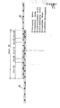
- each sealing membrane element has the same length of 8 m and the same height of 4 m, which cannot be seen in the drawing due to the cross-sectional representation.
- a sealing membrane of any length can be produced by joining together the various sealing membrane elements 1. While there is an excess length compared to the excavated soil, the sealing membrane is rolled up at one end or the sealing membrane can be cut to length there. Cutting to length is easy with the proposed plastic materials and without any noteworthy work.
- Each geomembrane element 1 has a welded tube 4 made of the same material at one end and a welded tube 2 made of the same material at the other end.
- the tube 2 is designed so that it can include the tube 4 - as shown in the drawing. This requires an inner diameter that is slightly larger than the outer diameter of the tube 4 and a slot over the entire length of the tube 2. The longitudinal slot enables the tube 2 to slide past the sealing membrane of the sealing membrane element 1 over the tube 4.
- the welding of the weld seam 2 can also be carried out with a separate device that can then run at twice the speed of the hot air nozzle and can be performed more safely and better with separate handling.
- the counter pressure element is preferably designed as a slide.
Abstract
Description
- Die Erfindung betrifft eine verschweißbare Abdichtungsbahn aus Thermoplasten, insbesondere aus Mischungen von Olefin-Copolymerisaten und angesättigten Carbonsäureestern und/oder Bitumen und/oder Füllstoffen für Dächer, Tunnel und Wasserbauten.
- Derartige Abdichtungsbahnen sind seit langem in der Anwendung. Der Rohstoff, aus dem die Bahnen hergestellt werden, beispielsweise eine Zusammensetzung aus 45-50 Gew.% eines Gemisches aus Polyethylen-Acrylsäureester-Copolymerisat und einem kleinen Anteil, etwa 10-15 Gew.%Hoch- druckpolyethylen und etwa 40 Gew.% Anthrazitstaub mit einer Körnung bis 30 u und einem Anteil an unbrennbaren Bestandteilen von bis zu 30 Gew.%.
- Zur Verschweißung werden die Bahnen an den Nahtstellen übereinandergelegt und im Überlappungsbereich durch entsprechende Erwärmung an den Berührungsflächen plastifiziert.
- Die Materialdicke der Bahn und die Schweißnaht sind jeweils so ausgelegt, daß Spannungsrisse im Rahmen der als zulässig ausgewiesenen Belastung an sich nicht auftreten können. Gleichwohl zeigen sich in Einzelfällen bei zulässiger Belastung Risse.
- Der Erfindung liegt die Aufgabe zugrunde, derartige Rißbildungen zu vermeiden.
- Dabei geht die Erfindung von dem Gedanken aus, daß die Bahnen einem natürlichen Schrumpf ausgesetzt sind, der in der Größenordnung zwischen 1 und 2 % liegt und sich insbesondere bei hohen Temperaturen ständig weiter fortsetzt. Dadurch entstehen Zugspannungen auch in Querrichtung zur Bahn auf die Schweißnähte. Die höchste Spannungskonzentration liegt dabei vor der Nahtkante. An dieser Stelle tritt einmal eine Zugkraft quer zur Nahtrichtung in der Unterbahn auf, bezüglich der Oberbahn bildet sich eine Kraftresultierende ebenfalls quer zur Nahtlinie; jedoch nicht in Bahnenebene, sondern vertikal zur Bahnenebene.
- Dieses Spannungsverhältnis äußert sich auch dadurch, daß im Laufe einer längeren Liegedauer die Bahn im Bereich der Nahtkante leicht aus der Bahnenebene herausgehoben wird und hier eine Art Wulst in Nahtrichtung bildet. Da die Kräfte je nach Temperaturlage ungleichmäßig angreifen, entsteht schließlich in der Unterbahn unmittelbar vor der Nahtkante ein leichter Kerbriß, der sich im Laufe der Zeit weiter ausbreitet und schließlich zu einer Rißbildung führt. Häufig ist an dieser Stelle bei glasfaservlieskaschierten Bahnen das unterhalb der Bahn auf kaschierte Glasvlies ebenfalls beschädigt oder sogar gebrochen.
- Nach der Erfindung wird diesem Schadensbild so entgegengewirkt, daß die auftretende Spannung abgeleitet wird, und zwar so, daß sie die äu3e-re Nahtkante unberührt läßt bzw. ein Aufwölben der Bahn an dieser Stelle ausgeschlossen wird.
- Nach der Erfindung wird das oben beschriebene Schadensbild dadurch vermieden, daß die Schweißnaht als Doppelnaht ausgebildet ist. Gegenüber einer Einfachschweißnaht ist die Unterbahn nach der Erfindung vor dem durch die einfache Schweißnaht gebildeten Befestigungspunkt zusätzlich mit der Oberbahn verschweißt. Auf diese Weise werden die Zugkräfte aus der Oberbahn über die zusätzliche Schweißstelle in die Unterbahn und damit in die Befestigung abgeleitet. Die oben liegende, äußere Naht wird somit nur noch durch Zugspannungen aus der Unterbahn beaufschlagt, die ungefährlich sind und nicht zu Kerbrissen vor der Naht führen können, da sie sich grundsätzlich in der gleichen Ebene auswirken und somit die Bahn in ihren Liegeverhalten nicht stören.
- Der Deckstreifen über der Befestigung bleibt damit nahezu spannungslos und führt zu einer wesentlich höheren Sicherheit für die Schweißnähte.
- Die doppelte Schweißnaht ist im übrigen eine zusätzliche Sicherheitsgarantie für die Dichtigkeit der einlagigen Abdichtung.
- Die auf die Dichtungsbahn aufzubringende Ortbetonschicht wird nach der Erfindung jeweils so ausgelegt, daß Ihr Gewicht die Auftriebskraft und die Dichte der thixotropen Masse (Bentonitschlempe) überwindet. Nach dem Absenken der Dichtungsbahnelemente können die nach oben hin offenen Rohrenden mit einer Kappe versehen oder ebenfalls mit Beton gefüllt werden.
- Die oben beschriebenen Dichtungsbahnelemente sind wesentlich dünner als vergleichbare Betonplatten. Im Ergebnis ermöglichen die erfindungsgemäßen Dichtungsbahnelemente eine Verringerung der Schlitzwänddicke gegenüber herkömmlichen Schlitzwänden auf die Hälfte.
- In der Zeichnung ist ein Ausführungsbeispiel der Erfindung dargestellt.
- Mit 1 sind verschiedene Dichtungsbahnelemente bezeichnet. Jedes Dichtungsbahnelement hat im Ausführungsbeispiel die gleiche Länge von 8 m und die gleiche, in der Zeichnung aufgrund der Querschnittsdarstellung nicht erkennbare Höhe von 4 m. Durch Aneinanderfügen der verschiedenen Dichtungsbahnelemente 1 kann eine Dichtungsbahn beliebiger Länge hergestellt werden. Während sich dabei eine Überlänge gegenüber dem auszuhebenden Erdschlïtz ergibt, wird die Dichtungsbahn an einem Ende aufgerollt oder läßt sich die Dichtungsbahn dort ablängen. Das Ablängen ist bei den vorgesehenen Kunststoffmaterialien einfach und ohne nennenswerten Arbeitsaufwand möglich. Jedes Dichtungsbahnelement 1 besitzt an einem Ende ein angeschweißtes Rohr 4 aus gleichem Material und am anderen Ende ein angeschweißtes Rohr 2 aus gleichem Material. Das Rohr 2 ist so ausgelegt, daß es das Rohr 4 - wie in der Zeichnung_dargestellt - umfassen kann. Das bedingt einen Innendurchmesser, der geringfügig größer als der Außendurchmesser des Rohres 4 ist, und einen Schlitz über die gesamte Länge des Rohres 2. Der Längsschlitz ermöglicht es dem Rohr 2, an der Dichtungsbahn des Dichtungsbahnelementes 1 vorbei über das Rohr.4 zu gleiten.
- Wahlweise kann die Schweißung der Schweißnaht 2 auch mit einem getrennten Gerät durchgeführt werden, daß dann mit doppelter Geschwindigkeit wie die Heißluftdüse fahren kann und bei getrennter Handhabung sicherer und besser zu führen ist. Das Gegendruckelement ist vorzugsweise als Schlitten ausgeführt.
Claims (6)
Priority Applications (1)
| Application Number | Priority Date | Filing Date | Title |
|---|---|---|---|
| AT85102152T ATE56238T1 (de) | 1984-06-14 | 1985-02-27 | Verschweissbare abdichtungsbahn. |
Applications Claiming Priority (2)
| Application Number | Priority Date | Filing Date | Title |
|---|---|---|---|
| DE19843422018 DE3422018A1 (de) | 1984-06-14 | 1984-06-14 | Verschweissbare abdichtungsbahn |
| DE3422018 | 1984-06-14 |
Publications (3)
| Publication Number | Publication Date |
|---|---|
| EP0164497A2 true EP0164497A2 (de) | 1985-12-18 |
| EP0164497A3 EP0164497A3 (en) | 1987-07-29 |
| EP0164497B1 EP0164497B1 (de) | 1990-09-05 |
Family
ID=6238296
Family Applications (1)
| Application Number | Title | Priority Date | Filing Date |
|---|---|---|---|
| EP85102152A Expired - Lifetime EP0164497B1 (de) | 1984-06-14 | 1985-02-27 | Verschweissbare Abdichtungsbahn |
Country Status (3)
| Country | Link |
|---|---|
| EP (1) | EP0164497B1 (de) |
| AT (1) | ATE56238T1 (de) |
| DE (2) | DE3422018A1 (de) |
Cited By (1)
| Publication number | Priority date | Publication date | Assignee | Title |
|---|---|---|---|---|
| CN104708808A (zh) * | 2015-01-26 | 2015-06-17 | 上海新帆实业股份有限公司 | 一种塑料封条自动焊接打码装置及其控制方法 |
Families Citing this family (1)
| Publication number | Priority date | Publication date | Assignee | Title |
|---|---|---|---|---|
| DE3940727C2 (de) * | 1989-12-09 | 2000-09-14 | Phoenix Ag | Bauwerksabdichtung, insbesondere Dachdichtungsbahnen |
Citations (3)
| Publication number | Priority date | Publication date | Assignee | Title |
|---|---|---|---|---|
| FR2215511A1 (de) * | 1973-01-27 | 1974-08-23 | Ruhrkohle Ag | |
| DE2358102A1 (de) * | 1973-11-21 | 1975-05-28 | Saar Gummiwerk Gmbh | Dachabdeckung aus lose verlegten dachhautbahnen |
| FR2393993A1 (fr) * | 1977-06-07 | 1979-01-05 | Caron Claude | Membrane d'etancheite de grande surface |
Family Cites Families (1)
| Publication number | Priority date | Publication date | Assignee | Title |
|---|---|---|---|---|
| DE2058762A1 (de) * | 1970-11-30 | 1972-05-31 | Dynamit Nobel Ag | Stehfaltdach |
-
1984
- 1984-06-14 DE DE19843422018 patent/DE3422018A1/de not_active Withdrawn
-
1985
- 1985-02-27 EP EP85102152A patent/EP0164497B1/de not_active Expired - Lifetime
- 1985-02-27 AT AT85102152T patent/ATE56238T1/de not_active IP Right Cessation
- 1985-02-27 DE DE8585102152T patent/DE3579499D1/de not_active Expired - Fee Related
Patent Citations (3)
| Publication number | Priority date | Publication date | Assignee | Title |
|---|---|---|---|---|
| FR2215511A1 (de) * | 1973-01-27 | 1974-08-23 | Ruhrkohle Ag | |
| DE2358102A1 (de) * | 1973-11-21 | 1975-05-28 | Saar Gummiwerk Gmbh | Dachabdeckung aus lose verlegten dachhautbahnen |
| FR2393993A1 (fr) * | 1977-06-07 | 1979-01-05 | Caron Claude | Membrane d'etancheite de grande surface |
Cited By (2)
| Publication number | Priority date | Publication date | Assignee | Title |
|---|---|---|---|---|
| CN104708808A (zh) * | 2015-01-26 | 2015-06-17 | 上海新帆实业股份有限公司 | 一种塑料封条自动焊接打码装置及其控制方法 |
| CN104708808B (zh) * | 2015-01-26 | 2017-05-24 | 上海新帆实业股份有限公司 | 一种塑料封条自动焊接打码装置及其控制方法 |
Also Published As
| Publication number | Publication date |
|---|---|
| ATE56238T1 (de) | 1990-09-15 |
| EP0164497A3 (en) | 1987-07-29 |
| DE3422018A1 (de) | 1985-12-19 |
| EP0164497B1 (de) | 1990-09-05 |
| DE3579499D1 (de) | 1990-10-11 |
Similar Documents
| Publication | Publication Date | Title |
|---|---|---|
| DE3703066C2 (de) | ||
| EP0268829B1 (de) | Dichtungsstreifen für Glasdächer und Glasfasaden | |
| DE3632951A1 (de) | Flexible abdichtungsbahn | |
| EP0164497A2 (de) | Verschweissbare Abdichtungsbahn | |
| EP0227878B1 (de) | Verbindungselemente für Schlitzwände | |
| EP0235353B1 (de) | Bruchsicherung an einer Schlitzwand | |
| DE19537444A1 (de) | Abdichtungsprofil zum Abdichten einer Fuge zwischen zwei Betonplatten | |
| DE3841553A1 (de) | Klebeanschluss von kunststoffdichtungsbahnen | |
| DE2233990C3 (de) | Vorrichtung zur Herstellung eines wenigstens gegen mechanische Kräfte gesicherten Anschlusses einer zur Abdichtung eines Bauwerkes verlegten Dichtungsbahn | |
| EP0157173B1 (de) | Verschweissbare Abdichtungsbahn | |
| DE4325953A1 (de) | Sperrsystem zum Schutz von Bauwerken gegen Eindringen von Radon aus dem Baugrund | |
| DE3800736C2 (de) | ||
| DE20319304U1 (de) | Fugendichtungselement | |
| DE2517575C3 (de) | Verfahren und Vorrichtung zum Verschweißen von PVC-Bändern, insbesondere Fugenbändern | |
| DE3717586C2 (de) | Deponieabdichtung | |
| DE3401947C2 (de) | ||
| DE10103497C1 (de) | Verfahren zum Unterbrechen der kapillaren Feuchtigkeitsförderung an Bauwerken | |
| DE4314369C2 (de) | Deponie-Abdichtung | |
| DE3605252A1 (de) | Hakenprofil fuer schlitzwand zur vertikalabdichtung | |
| EP0517229A1 (de) | Deponie-Abdichtung | |
| AT405873B (de) | Rohrverbindung | |
| DE4100466A1 (de) | Verfahren zum nachtraeglichen einbau einer dichtungssohle unter einer altlast | |
| DE1242956B (de) | Verschluss- und Dichtungsband fuer Fugen, insbesondere fuer Muffenrohrverbindungen | |
| DE1269322B (de) | Verfahren zum Abdichten von Fugen zwischen Fertigbetonbauteilen | |
| DE3902522A1 (de) | Schweissen von kunststoffabdichtungsbahnen in erdschlitzen |
Legal Events
| Date | Code | Title | Description |
|---|---|---|---|
| PUAI | Public reference made under article 153(3) epc to a published international application that has entered the european phase |
Free format text: ORIGINAL CODE: 0009012 |
|
| AK | Designated contracting states |
Designated state(s): AT BE CH DE FR GB IT LI NL SE |
|
| PUAL | Search report despatched |
Free format text: ORIGINAL CODE: 0009013 |
|
| AK | Designated contracting states |
Kind code of ref document: A3 Designated state(s): AT BE CH DE FR GB IT LI NL SE |
|
| 17P | Request for examination filed |
Effective date: 19870619 |
|
| 17Q | First examination report despatched |
Effective date: 19880802 |
|
| ITF | It: translation for a ep patent filed |
Owner name: BARZANO' E ZANARDO ROMA S.P.A. |
|
| GRAA | (expected) grant |
Free format text: ORIGINAL CODE: 0009210 |
|
| AK | Designated contracting states |
Kind code of ref document: B1 Designated state(s): AT BE CH DE FR GB IT LI NL SE |
|
| REF | Corresponds to: |
Ref document number: 56238 Country of ref document: AT Date of ref document: 19900915 Kind code of ref document: T |
|
| ET | Fr: translation filed | ||
| REF | Corresponds to: |
Ref document number: 3579499 Country of ref document: DE Date of ref document: 19901011 |
|
| GBT | Gb: translation of ep patent filed (gb section 77(6)(a)/1977) | ||
| PGFP | Annual fee paid to national office [announced via postgrant information from national office to epo] |
Ref country code: FR Payment date: 19910111 Year of fee payment: 7 |
|
| PGFP | Annual fee paid to national office [announced via postgrant information from national office to epo] |
Ref country code: SE Payment date: 19910115 Year of fee payment: 7 |
|
| PGFP | Annual fee paid to national office [announced via postgrant information from national office to epo] |
Ref country code: CH Payment date: 19910124 Year of fee payment: 7 |
|
| PGFP | Annual fee paid to national office [announced via postgrant information from national office to epo] |
Ref country code: NL Payment date: 19910228 Year of fee payment: 7 |
|
| RAP2 | Party data changed (patent owner data changed or rights of a patent transferred) |
Owner name: HUELS TROISDORF AKTIENGESELLSCHAFT |
|
| PGFP | Annual fee paid to national office [announced via postgrant information from national office to epo] |
Ref country code: AT Payment date: 19910315 Year of fee payment: 7 |
|
| NLT2 | Nl: modifications (of names), taken from the european patent patent bulletin |
Owner name: HUELS TROISDORF AKTIENGESELLSCHAFT TE TROISDORF, B |
|
| PLBE | No opposition filed within time limit |
Free format text: ORIGINAL CODE: 0009261 |
|
| STAA | Information on the status of an ep patent application or granted ep patent |
Free format text: STATUS: NO OPPOSITION FILED WITHIN TIME LIMIT |
|
| 26N | No opposition filed | ||
| PGFP | Annual fee paid to national office [announced via postgrant information from national office to epo] |
Ref country code: BE Payment date: 19911211 Year of fee payment: 8 |
|
| BECN | Be: change of holder's name |
Effective date: 19910306 |
|
| PGFP | Annual fee paid to national office [announced via postgrant information from national office to epo] |
Ref country code: GB Payment date: 19920214 Year of fee payment: 8 |
|
| PG25 | Lapsed in a contracting state [announced via postgrant information from national office to epo] |
Ref country code: AT Effective date: 19920227 |
|
| PG25 | Lapsed in a contracting state [announced via postgrant information from national office to epo] |
Ref country code: SE Effective date: 19920228 |
|
| PG25 | Lapsed in a contracting state [announced via postgrant information from national office to epo] |
Ref country code: LI Effective date: 19920229 Ref country code: CH Effective date: 19920229 |
|
| PGFP | Annual fee paid to national office [announced via postgrant information from national office to epo] |
Ref country code: DE Payment date: 19920413 Year of fee payment: 8 |
|
| PG25 | Lapsed in a contracting state [announced via postgrant information from national office to epo] |
Ref country code: NL Effective date: 19920901 |
|
| NLV4 | Nl: lapsed or anulled due to non-payment of the annual fee | ||
| PG25 | Lapsed in a contracting state [announced via postgrant information from national office to epo] |
Ref country code: FR Effective date: 19921030 |
|
| REG | Reference to a national code |
Ref country code: CH Ref legal event code: PL |
|
| REG | Reference to a national code |
Ref country code: FR Ref legal event code: ST |
|
| PG25 | Lapsed in a contracting state [announced via postgrant information from national office to epo] |
Ref country code: GB Effective date: 19930227 |
|
| PG25 | Lapsed in a contracting state [announced via postgrant information from national office to epo] |
Ref country code: BE Effective date: 19930228 |
|
| BERE | Be: lapsed |
Owner name: HULS TROISDORF A.G. Effective date: 19930228 |
|
| GBPC | Gb: european patent ceased through non-payment of renewal fee |
Effective date: 19930227 |
|
| PG25 | Lapsed in a contracting state [announced via postgrant information from national office to epo] |
Ref country code: DE Effective date: 19931103 |
|
| EUG | Se: european patent has lapsed |
Ref document number: 85102152.7 Effective date: 19920904 |