EP0160007B1 - Nadelbandwebmaschine - Google Patents
Nadelbandwebmaschine Download PDFInfo
- Publication number
- EP0160007B1 EP0160007B1 EP84903478A EP84903478A EP0160007B1 EP 0160007 B1 EP0160007 B1 EP 0160007B1 EP 84903478 A EP84903478 A EP 84903478A EP 84903478 A EP84903478 A EP 84903478A EP 0160007 B1 EP0160007 B1 EP 0160007B1
- Authority
- EP
- European Patent Office
- Prior art keywords
- needle
- drive
- rocker arm
- coupling rod
- weaving machine
- Prior art date
- Legal status (The legal status is an assumption and is not a legal conclusion. Google has not performed a legal analysis and makes no representation as to the accuracy of the status listed.)
- Expired
Links
- 238000009941 weaving Methods 0.000 title claims abstract description 20
- 230000008878 coupling Effects 0.000 claims abstract description 21
- 238000010168 coupling process Methods 0.000 claims abstract description 21
- 238000005859 coupling reaction Methods 0.000 claims abstract description 21
- 235000014676 Phragmites communis Nutrition 0.000 abstract description 23
- 238000009940 knitting Methods 0.000 abstract description 5
- 230000002411 adverse Effects 0.000 description 1
- 230000002349 favourable effect Effects 0.000 description 1
- 239000007787 solid Substances 0.000 description 1
- 238000011144 upstream manufacturing Methods 0.000 description 1
Images
Classifications
-
- D—TEXTILES; PAPER
- D03—WEAVING
- D03D—WOVEN FABRICS; METHODS OF WEAVING; LOOMS
- D03D47/00—Looms in which bulk supply of weft does not pass through shed, e.g. shuttleless looms, gripper shuttle looms, dummy shuttle looms
- D03D47/02—Looms in which bulk supply of weft does not pass through shed, e.g. shuttleless looms, gripper shuttle looms, dummy shuttle looms wherein loops of continuous weft thread are inserted, i.e. double picks
- D03D47/06—Looms in which bulk supply of weft does not pass through shed, e.g. shuttleless looms, gripper shuttle looms, dummy shuttle looms wherein loops of continuous weft thread are inserted, i.e. double picks by a pivoted needle having a permanently-threaded eye
-
- D—TEXTILES; PAPER
- D03—WEAVING
- D03D—WOVEN FABRICS; METHODS OF WEAVING; LOOMS
- D03D47/00—Looms in which bulk supply of weft does not pass through shed, e.g. shuttleless looms, gripper shuttle looms, dummy shuttle looms
- D03D47/27—Drive or guide mechanisms for weft inserting
- D03D47/275—Drive mechanisms
Definitions
- the invention relates to a needle ribbon loom according to the preamble of claim 1.
- Needle ribbon looms of the type mentioned are known, for example from CH-PS 633 331.
- both the weft needle drive and the reed drive are driven from a common main drive shaft.
- a disc with a crank is arranged on the latter and has diametrically opposed pin journals, of which one crank pin is connected to the weft needle drive via a connecting rod and the other crank pin is likewise connected to the reed drive by means of a connecting rod.
- the reed drive and the weft needle drive experience an opposite movement. Good results are already achieved with such a needle ribbon weaving machine. However, it has been shown that there is still nothing to be desired in terms of both noise development and drive power.
- a needle ribbon loom is known in which the main drive shaft is not directly connected to the reed drive, but first to the weft drive. Only from the latter is the reed drive connected via a coupling element. Since the reed drive is exposed to higher loads than the weft needle drive when the weft thread is struck, the load on the reed drive is also passed on to the weft drive, which is very disadvantageous and which promotes a deflection of the weft drive.
- the weft needle drive upstream of the reed drive must accordingly be made more solid than is necessary for itself, which results in a higher mass inertia and higher drive forces are required which adversely affect the performance.
- the object of the invention is therefore to further improve a needle ribbon loom of the type mentioned at the outset, so that the noise is reduced and the performance is increased.
- the stated object is surprisingly achieved by the characterizing features of claim 1.
- the fact that the weft needle drive is no longer independently connected to the main drive shaft via a crank pin, but rather is connected to a rocker arm of the reed drive via a coupling rod, has the advantage that, surprisingly, a significant increase in the performance of the needle ribbon loom is possible while at the same time reducing it noise and wear is achieved.
- rocking levers to which the coupling rod of the weft needle drive is connected can have different lengths, but an embodiment according to claim 3 is more advantageous.
- a further improvement in terms of performance increase and noise reduction is possible through a further development according to claim 4.
- the rocker arms to which the coupling rod is connected can point in the same direction according to claim 6, particularly advantageous conditions result if the rocker arms point in opposite directions according to claim 5. This favors the mass balance of the drives.
- Claim 7 shows a very simple solution of the needle ribbon weaving machine, since an additional rocking lever on the reed drive can be dispensed with here.
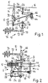
- the weaving machine shown schematically in FIGS. 1 and 2 contains a main drive shaft 2 to which a weft needle drive 4, a knitting needle drive 8 and a shedding frame drive 10 are connected via a reed drive 6. Warp threads 12, the warp pocket 14 and a woven band 16 are also indicated.
- a disk 18 is arranged on the main drive shaft 2 and contains a crank pin 22 which is guided in a radially adjustable manner in a dovetail-shaped groove 20, so that the eccentricity of the crank pin can be adjusted.
- a connecting rod 24 is connected to the crank pin 22 and is fastened via a hinge pin 26 to a rocker arm 28 which is connected in a rotationally fixed manner to a shaft 30.
- a longitudinal guide 32 arranged in the rocker arm 28 is used to adjust the effective lever length of the rocker arm 28.
- An arm 34 is also arranged on the shaft 30 in a rotationally fixed manner and carries a reed 36 at its free end.
- a rocker arm 38 is rotatably attached, to which a coupling rod 40 of the weft needle drive 4 is articulated, which in turn is articulated to a rocker arm 42 which is rotatably connected to a shaft 44 which carries a further rocker arm 46, on which another Coupling rod 48, a further rocker arm 50 is connected, which is fixed to a vertical shaft 52.
- the latter carries the weft needle 54 which engages in the warp compartment 14 at the upper end.
- FIGS. 1 and 2 also show the knitting needle drive 8, which has a cam disk 56 arranged on the main drive shaft 2, on which a driver 58 of a two-armed rocking lever 60 engages.
- a spring 62 presses the driver 58 against the cam disk 56.
- a knitting needle 64 is fastened, which acts in a known manner on one side of the band to be produced and for tying the warp needle 54 into the warp shed registered weft loops.
- the compartment drive 10 which is also connected to the main drive shaft 2, contains a single-stage gear 66, which is formed from a worm 68, which is connected to the main drive shaft 2, and a worm wheel 70, which is seated on a secondary drive shaft 72, to which various eccentrics 74 are fastened which drive shafts in a known, not shown manner.
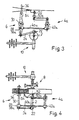
- the needle ribbon weaving machine shown schematically in FIGS. 3 and 4 corresponds to that of FIGS. 1 and 2, but the coupling of the weft needle drive 4a to the reed drive 6 is modified such that the.
- Coupling rod 40a is arranged on rectified rocker arms 38a and 42a.
- the rocker arm 38a connected to the shaft 30 of the reed drive 6 is formed by the rocker arm 28 of the reed drive 6. Since the rocker arm 42a points in the same direction as the rocker arm 38a, the rocker arms move in the same direction.
- the rocker arm 50a is on the same side of the shaft 52 to which the weft needle 54 is also attached. This in turn results in an opposite movement between the weft needle 54 and the reed 36.
- the length of the rocker arms 38, 38a and 42, 42a is shorter than the length of the rocker arm 28 connected to the connecting rod 24.
Landscapes
- Engineering & Computer Science (AREA)
- Textile Engineering (AREA)
- Looms (AREA)
Description
- Die Erfindung betrifft eine Nadelbandwebmaschine gemäss Oberbegriff des Anspruches 1.
- Nadelbandwebmaschinen der eingangs genannten Art sind bekannt, so beispielsweise aus der CH-PS 633 331. Bei dieser bekannten Nadelbandwebmaschine werden sowohl der Schussnadelantrieb wie der Webblattantrieb von einer gemeinsamen Hauptantriebswelle aus angetrieben. An letzterer ist eine Scheibe mit einer Kurbel angeordnet, die diametral gegenüberliegende Kutbelzapfen aufweist, von denen ein Kurbelzapfen über eine Pleuelstange mit dem Schussnadelantrieb und der andere Kurbelzapfen ebenfalls mittels einer Pleuelstange mit dem Webblattantrieb verbunden sind. Der Webblattantrieb und der Schussnadelantrieb erfahren dadurch eine gegenläufige Bewegung. Mit einer solchen Nadelbandwebmaschine werden bereits gute Ergebnisse erzielt. Es hat sich jedoch gezeigt, dass sowohl von der Geräuschentwicklung wie von der Antriebsleistung noch Wünsche offen sind.
- Aus der GB-PS 1 397 054 ist eine Nadelbandwebmaschine bekannt, bei der die Hauptantriebswelle nicht direkt mit dem Webblattantrieb verbunden ist, sondern zunächst mit dem Schussnadelantrieb. Erst von letzterem ist über ein Koppelglied der Webblattantrieb angeschlossen. Da der Webblattantrieb durch das Anschlagen des Schussfadens höheren Belastungen ausgesetzt ist als der Schussnadelantrieb, so wird die Belastung des Webblattantriebes auch auf den Schussnadelantrieb weitergegeben, was sehr nachteilig ist und wodurch ein Ausschlagen des Schussnadelantriebes gefördert wird. Der dem Webblattantrieb vorgeschaltete Schussnadelantrieb muss demnach massiver ausgebildet sein, als für sich erforderlich, wodurch eine höhere Massenträgheit gegeben ist und höhere Antriebskräfte erforderlich sind, die die teistung nachteilig beeinflussen.
- Aufgabe der Erfindung ist es deshalb, eine Nadelbandwebmaschine der eingangs genannten Art weiter zu verbessern, sodass die Geräuschentwicklung vermindert und die Leistungsfähigkeit gesteigert werden.
- Die gestellte Aufgabe wird in überraschender Weise durch die kennzeichnenden Merkmale des Anspruches 1 gelöst. Dadurch, dass der Schussnadelantrieb nicht mehr selbständig über einen Kurbelzapfen an der Hauptantriebswelle angeschlossen ist, sondern über eine Koppelstange mit einem Schwinghebel des Webblattantriebes verbunden ist, ergibt sich der Vorteil, dass in überraschender Weise eine wesentliche Leistungssteigerung der Nadelbandwebmaschine möglich ist, während gleichzeitig eine Verminderung der Lärmentwicklung und des Verschleisses erzielt wird.
- Vorteilhafte Ausgestaltungen der Nadelbandwebmaschine sind in den Ansprüchen 2 bis 7 umschrieben.
- Besonders günstige Verhältnisse hinsichtlich Leistungssteigerung und Lärmverminderung lassen sich mit einer Ausbildung nach Anspruch 2 erzielen. An sich können die Schwinghebel, an denen die Koppelstange des schussnadelantriebes angeschlossen ist, unterschiedliche Längen aufweisen, vorteilhafter ist jedoch eine Ausbildung nach Anspruch 3. Eine weitere Verbesserung hinsichtlich Leistungssteigerung und Geräuschverminderung ist durch eine Weiterbildung nach Anspruch 4 möglich. Obwohl die Schwinghebel, an denen die Koppelstange angeschlossen ist, gemäss Anspruch 6 in gleiche Richtung weisen können, ergeben sich besonders vorteilhafte Bedingungen, wenn die Schwinghebel gemäss Anspruch 5 in entgegengesetzte Richtungen weisen. Dies begünstigt den Massenausgleich der Antriebe.
- Eine sehr einfache Lösung der Nadelbandwebmaschine zeigt Anspruch 7, da hier auf einen zusätzlichen Schwinghebel am Webblattantrieb verzichtet werden kann.
- Ausführungsbeispiele der erfindungsgemässen Nadelbandwebmaschine werden anhand schematischer Zeichnungen näher beschrieben, dabei zeigen :
- Figur 1 eine erste Nadelbandwebmaschine, bei der die am Webblattantrieb angeschlossene Koppelstange des Schussnadelantriebes an gegeneinander gerichteten Schwinghebeln angeordnet ist, in Seitenansicht;
- Figur 2 die Nadelbandwebmaschine der Figur 1 im Grundriss ;
- Figur 3 eine zweite Nadelbandwebmaschine, bei der die am Webblattantrieb angeschlossene Koppelstange des Schussnadelantriebes an in gleiche Richtung weisenden Schwinghebeln angeordnet ist, in Seitenansicht; und
- Figur 4 die Nadelbandwebmaschine der Figur 3 im Grundriss.
- Die in den Figuren 1 und 2 schematisch dargestellte Webmaschine enthält eine Hauptantriebswelle 2, an der über einen Webblattantrieb 6 ein Schussnadelantrieb 4, ein Wirknadelantrieb 8 und ein Fachbildeantrieb 10 angeschlossen sind. Ferner sind Kettfäden 12, das Kettfach 14 und ein gewobenes Band 16 angedeutet.
- An der Hauptantriebswelle 2 ist eine Scheibe 18 angeordnet, die einen in einer schwalbenschwanzförmigen Nut 20 radial verstellbar geführten Kurbelzapfen 22 enthält, sodass die Exzentrizität des Kurbelzapfens einstellbar ist. An dem Kurbelzapfen 22 ist eine Pleuelstange 24 angeschlossen, die über einen Gelenkbolzen 26 an einem Schwinghebel 28 befestigt ist, der drehfest mit einer Welle 30 verbunden ist.
- Eine im Schwinghebel 28 angeordnete Längsführung 32 dient zur Einstellung der wirksamen Hebellänge des Schwinghebels 28. An der Welle 30 ist weiter ein Arm 34 drehfest angeordnet, der an seinem freien Ende ein Webblatt 36 trägt.
- An der Welle 30 des Webblattantriebes 6 ist weiter ein Schwinghebel 38 drehfest befestigt, an dem eine Koppelstange 40 des Schussnadelantriebes 4 gelenkig angeschlossen ist, die wiederum mit einem Schwinghebel 42 gelenkig verbunden ist, welcher drehfest mit einer Welle 44 verbunden ist, welche einen weiteren Schwinghebel 46 trägt, an dem über eine weitere Koppelstange 48 ein weiterer Schwinghebel 50 angeschlossen ist, der an einer vertikalen Welle 52 befestigt ist. Letztere trägt am oberen Ende die in das Kettfach 14 eingreifende Schussnadel 54.
- Bei der in den Figuren 1 und 2 dargestellten mittleren Bewegungsphase des Webblattantriebes 6 bilden die gegeneinander gerichteten und gleichlangen Schwinghebel 38, 42 einen rechten Winkel mit der Koppelstange 40.
- In den Figuren 1 und 2 ist weiter der Wirknadelantrieb 8 gezeigt, welcher eine an der Hauptantriebswelle 2 angeordnete Kurvenscheibe 56 besitzt, an der ein Mitnehmer 58 eines zweiarmigen Schwinghebels 60 angreift. Eine Feder 62 drückt den Mitnehmer 58 an die Kurvenscheibe 56. An dem dem Mitnehmer 58 abgewandten Ende des Schwinghebels 60 ist eine Wirknadel 64 befestigt, die in bekannter Weise an einer Seite des herzustellenden Bandes angreift und zum Abbinden der mittels der Schussnadel 54 in das Kettfach eingetragenen Schussfadenschlaufen dient.
- Der ebenfalls an der Hauptantriebswelle 2 angeschlossene Fachbildeantrieb 10 enthält ein einstufiges Getriebe 66, welches aus einer Schnecke 68, die mit der Hauptantriebswelle 2 verbunden ist, und einem Schneckenrad 70 gebildet ist, welches auf einer Nebenantriebswelle 72 sitzt, an der verschiedene Exzenter 74 befestigt sind, die in bekannter, nicht näher dargestellter Weise Schäfte antreiben.
- Die in den Figuren 3 und 4 schematisch gezeigte Nadelbandwebmaschine entspricht jener der Figuren 1 und 2, wobei jedoch die Kopplung des Schussnadelantriebes 4a mit dem Webblattantrieb 6 dahingehend abgewandelt ist, dass die . Koppelstange 40a an gleichgerichteten Schwinghebeln 38a und 42a angeordnet ist. Dabei wird der mit der Welle 30 des Webblattantriebes 6 verbundene Schwinghebel 38a durch den Schwinghebel 28 des Webblattantriebes 6 gebildet. Da der Schwinghebel 42a in gleiche Richtung weist wie der Schwinghebel 38a, erfolgt die Bewegung der Schwinghebel gleichläufig. Um dennoch eine gegenläufige Bewegung zwischen dem Webblatt 36 und der Schussnadel 54 zu erhalten, liegt der Schwinghebel 50a auf der gleichen Seite der Welle 52, an der auch die Schussnadel 54 befestigt ist. Dadurch ergibt sich wiederum eine gegenläufige Bewegung zwischen der Schussnadel 54 und dem Webblatt 36.
- Wie in den Beispielen gezeigt, ist die Länge der Schwinghebel 38, 38a sowie 42, 42a kürzer als die Länge des mit der Pleuelstange 24 verbundenen Schwinghebels 28.
Claims (7)
Priority Applications (1)
| Application Number | Priority Date | Filing Date | Title |
|---|---|---|---|
| AT84903478T ATE33154T1 (de) | 1983-10-06 | 1984-09-27 | Nadelbandwebmaschine. |
Applications Claiming Priority (2)
| Application Number | Priority Date | Filing Date | Title |
|---|---|---|---|
| CH5434/83 | 1983-10-06 | ||
| CH5434/83A CH661067A5 (de) | 1983-10-06 | 1983-10-06 | Nadelbandwebmaschine. |
Publications (2)
| Publication Number | Publication Date |
|---|---|
| EP0160007A1 EP0160007A1 (de) | 1985-11-06 |
| EP0160007B1 true EP0160007B1 (de) | 1988-03-23 |
Family
ID=4293522
Family Applications (1)
| Application Number | Title | Priority Date | Filing Date |
|---|---|---|---|
| EP84903478A Expired EP0160007B1 (de) | 1983-10-06 | 1984-09-27 | Nadelbandwebmaschine |
Country Status (7)
| Country | Link |
|---|---|
| US (1) | US4657053A (de) |
| EP (1) | EP0160007B1 (de) |
| BR (1) | BR8407116A (de) |
| CH (1) | CH661067A5 (de) |
| DE (1) | DE3345835C2 (de) |
| IT (1) | IT1207568B (de) |
| WO (1) | WO1985001524A1 (de) |
Families Citing this family (6)
| Publication number | Priority date | Publication date | Assignee | Title |
|---|---|---|---|---|
| CH673038A5 (de) * | 1986-12-04 | 1990-01-31 | Textilma Ag | |
| JPH06212537A (ja) * | 1993-01-19 | 1994-08-02 | Yoshida Kogyo Kk <Ykk> | 織 機 |
| FR2870548B1 (fr) * | 2004-05-19 | 2006-06-30 | Staubli Lyon Sa | Dispositif d'entrainement d'aiguilles de maillage et metier a tisser equipe d'un tel dispositif |
| GB2465744A (en) * | 2008-11-04 | 2010-06-02 | John Dalton Griffith | Rapier loom drive mechanism |
| CN102704148A (zh) * | 2012-07-06 | 2012-10-03 | 常熟市天豪机械有限公司 | 织带装置 |
| CN105755651B (zh) * | 2016-04-26 | 2017-07-07 | 江苏友诚数控科技有限公司 | 一种织机的引纬打纬机构 |
Citations (1)
| Publication number | Priority date | Publication date | Assignee | Title |
|---|---|---|---|---|
| CH633331A5 (de) * | 1978-10-25 | 1982-11-30 | Textilma Ag | Nadelbandwebmaschine. |
Family Cites Families (6)
| Publication number | Priority date | Publication date | Assignee | Title |
|---|---|---|---|---|
| GB1397054A (en) * | 1973-02-09 | 1975-06-11 | Bonas Machine Co | Narrow fabric looms |
| IT992532B (it) * | 1973-05-04 | 1975-09-30 | Doriguzzi Sas | Dispositivo per l azionamento degli aghi portatrama nei telai tessili senza navetta |
| US3901285A (en) * | 1974-02-08 | 1975-08-26 | John Dalton Griffith | Narrow fabric loom |
| JPS54172064U (de) * | 1978-05-09 | 1979-12-05 | ||
| US4243076A (en) * | 1978-06-08 | 1981-01-06 | Mallard Robert G | Loom rapier drive mechanism |
| CH633329A5 (en) * | 1978-08-14 | 1982-11-30 | Textilma Ag | Gear for converting a rotational movement into an oscillating movement for a textile machine, especially for a ribbon loom, and use of the gear |
-
1983
- 1983-10-06 CH CH5434/83A patent/CH661067A5/de not_active IP Right Cessation
- 1983-12-19 DE DE3345835A patent/DE3345835C2/de not_active Expired
-
1984
- 1984-09-27 EP EP84903478A patent/EP0160007B1/de not_active Expired
- 1984-09-27 US US06/744,002 patent/US4657053A/en not_active Expired - Lifetime
- 1984-09-27 BR BR8407116A patent/BR8407116A/pt not_active IP Right Cessation
- 1984-09-27 WO PCT/CH1984/000157 patent/WO1985001524A1/de not_active Ceased
- 1984-10-04 IT IT8422992A patent/IT1207568B/it active
Patent Citations (1)
| Publication number | Priority date | Publication date | Assignee | Title |
|---|---|---|---|---|
| CH633331A5 (de) * | 1978-10-25 | 1982-11-30 | Textilma Ag | Nadelbandwebmaschine. |
Also Published As
| Publication number | Publication date |
|---|---|
| IT1207568B (it) | 1989-05-25 |
| BR8407116A (pt) | 1985-08-27 |
| WO1985001524A1 (fr) | 1985-04-11 |
| US4657053A (en) | 1987-04-14 |
| DE3345835A1 (de) | 1984-06-20 |
| CH661067A5 (de) | 1987-06-30 |
| IT8422992A0 (it) | 1984-10-04 |
| EP0160007A1 (de) | 1985-11-06 |
| DE3345835C2 (de) | 1986-04-24 |
Similar Documents
| Publication | Publication Date | Title |
|---|---|---|
| DE2939883C2 (de) | Nadelbandwebmaschine | |
| EP0160007B1 (de) | Nadelbandwebmaschine | |
| EP1489209B1 (de) | Weblitze | |
| EP0446560B1 (de) | Ladetrieb für eine Webmaschine mit exzentrischer Ladewelle | |
| DE69029219T2 (de) | Verschiebbare Vorrichtung zum Realisieren von mit Schlitzdreherlitze gewebten Kanten auf schützenlosen Webmaschinen | |
| DE4404451C2 (de) | Dreherleistenvorrichtung | |
| EP1500732B1 (de) | Webblatt und Lamelle | |
| DE1785134A1 (de) | Nadelwebstuhl zum Herstellen von Baendern,Riemen,Guerteln u.dgl. | |
| DE2444411B2 (de) | Bandwebmaschine mit mehreren mit litzen versehenen schaeften | |
| DE2651057A1 (de) | Weblitze | |
| EP0158651A1 (de) | Kettenwirkmaschine, insbesondere häkelgalonmaschine. | |
| DE19730393C2 (de) | Gittergewebe | |
| DE69201039T2 (de) | Doppelspannfeder für die Weblitzen einer Jacquard, Verdol oder ähnlichen Webmaschine. | |
| EP0269951B1 (de) | Nadelbandwebmaschine | |
| DE2446225C2 (de) | Frottier-Webmaschine | |
| DE60309921T2 (de) | Vorrichtung zur durchführung der programmierung von drehbaren schaftmaschinen bei webmaschinen | |
| DE69607368T2 (de) | Schussfadenschneidvorrichtung für webmaschinen | |
| DE10127098C1 (de) | Vorrichtung zur Übertragung von Bewegungen und Kräften, insbesondere in Schaftwebmaschinen | |
| DE165265C (de) | ||
| DE68909030T2 (de) | Asymmetrisch geformter Webschaft für Webmaschinen. | |
| AT223549B (de) | Verfahren und Einrichtung zum stoßfreien Antrieb von aus einer Ruhelage in eine andere zu bewegenden Maschinenelementen, insbesondere von Schäften von Webstühlen | |
| DE2153243C3 (de) | Schützenlose Webmaschine für Doppelflorgewebe | |
| WO1999064652A1 (de) | Webmaschine | |
| AT215054B (de) | Vorrichtung zum Durchwirken von Textilflächengebilden | |
| CH628098A5 (de) | Antriebsvorrichtung fuer einen teilmechanismus einer webmaschine. |
Legal Events
| Date | Code | Title | Description |
|---|---|---|---|
| PUAI | Public reference made under article 153(3) epc to a published international application that has entered the european phase |
Free format text: ORIGINAL CODE: 0009012 |
|
| 17P | Request for examination filed |
Effective date: 19850613 |
|
| AK | Designated contracting states |
Designated state(s): AT BE FR GB LU NL SE |
|
| 17Q | First examination report despatched |
Effective date: 19861021 |
|
| R17C | First examination report despatched (corrected) |
Effective date: 19861030 |
|
| GRAA | (expected) grant |
Free format text: ORIGINAL CODE: 0009210 |
|
| AK | Designated contracting states |
Kind code of ref document: B1 Designated state(s): AT BE FR GB LU NL SE |
|
| PG25 | Lapsed in a contracting state [announced via postgrant information from national office to epo] |
Ref country code: NL Effective date: 19880323 Ref country code: BE Effective date: 19880323 |
|
| REF | Corresponds to: |
Ref document number: 33154 Country of ref document: AT Date of ref document: 19880415 Kind code of ref document: T |
|
| PG25 | Lapsed in a contracting state [announced via postgrant information from national office to epo] |
Ref country code: SE Effective date: 19880331 |
|
| ET | Fr: translation filed | ||
| GBT | Gb: translation of ep patent filed (gb section 77(6)(a)/1977) | ||
| NLV1 | Nl: lapsed or annulled due to failure to fulfill the requirements of art. 29p and 29m of the patents act | ||
| PG25 | Lapsed in a contracting state [announced via postgrant information from national office to epo] |
Ref country code: AT Effective date: 19880927 |
|
| PG25 | Lapsed in a contracting state [announced via postgrant information from national office to epo] |
Ref country code: LU Free format text: LAPSE BECAUSE OF NON-PAYMENT OF DUE FEES Effective date: 19880930 |
|
| PLBE | No opposition filed within time limit |
Free format text: ORIGINAL CODE: 0009261 |
|
| STAA | Information on the status of an ep patent application or granted ep patent |
Free format text: STATUS: NO OPPOSITION FILED WITHIN TIME LIMIT |
|
| 26N | No opposition filed | ||
| REG | Reference to a national code |
Ref country code: GB Ref legal event code: IF02 |
|
| PGFP | Annual fee paid to national office [announced via postgrant information from national office to epo] |
Ref country code: GB Payment date: 20030827 Year of fee payment: 20 |
|
| PGFP | Annual fee paid to national office [announced via postgrant information from national office to epo] |
Ref country code: FR Payment date: 20030904 Year of fee payment: 20 |
|
| PG25 | Lapsed in a contracting state [announced via postgrant information from national office to epo] |
Ref country code: GB Free format text: LAPSE BECAUSE OF EXPIRATION OF PROTECTION Effective date: 20040926 |
|
| REG | Reference to a national code |
Ref country code: GB Ref legal event code: PE20 |