EP0159690A2 - Verfahren zum Kontrollieren des Sinterns von Metallpulvern - Google Patents
Verfahren zum Kontrollieren des Sinterns von Metallpulvern Download PDFInfo
- Publication number
- EP0159690A2 EP0159690A2 EP85104885A EP85104885A EP0159690A2 EP 0159690 A2 EP0159690 A2 EP 0159690A2 EP 85104885 A EP85104885 A EP 85104885A EP 85104885 A EP85104885 A EP 85104885A EP 0159690 A2 EP0159690 A2 EP 0159690A2
- Authority
- EP
- European Patent Office
- Prior art keywords
- sintering
- metal particles
- particles
- metal
- ceramic
- Prior art date
- Legal status (The legal status is an assumption and is not a legal conclusion. Google has not performed a legal analysis and makes no representation as to the accuracy of the status listed.)
- Granted
Links
- 238000005245 sintering Methods 0.000 title claims abstract description 63
- 239000002923 metal particle Substances 0.000 title claims abstract description 40
- 238000000034 method Methods 0.000 title claims description 19
- 239000002245 particle Substances 0.000 claims abstract description 41
- 229910052751 metal Inorganic materials 0.000 claims abstract description 31
- 239000002184 metal Substances 0.000 claims abstract description 31
- 230000004888 barrier function Effects 0.000 claims abstract description 15
- 229920002037 poly(vinyl butyral) polymer Polymers 0.000 claims abstract description 15
- 239000004372 Polyvinyl alcohol Substances 0.000 claims abstract description 5
- 229920002451 polyvinyl alcohol Polymers 0.000 claims abstract description 5
- 239000004593 Epoxy Substances 0.000 claims abstract description 4
- 125000003700 epoxy group Chemical group 0.000 claims abstract description 4
- 229920000647 polyepoxide Polymers 0.000 claims abstract description 4
- 150000003673 urethanes Chemical class 0.000 claims abstract description 4
- 229920002554 vinyl polymer Polymers 0.000 claims abstract description 4
- RYGMFSIKBFXOCR-UHFFFAOYSA-N Copper Chemical compound [Cu] RYGMFSIKBFXOCR-UHFFFAOYSA-N 0.000 claims description 35
- 229910052802 copper Inorganic materials 0.000 claims description 32
- 239000010949 copper Substances 0.000 claims description 32
- 230000001590 oxidative effect Effects 0.000 claims description 14
- 238000010438 heat treatment Methods 0.000 claims description 8
- PXHVJJICTQNCMI-UHFFFAOYSA-N Nickel Chemical compound [Ni] PXHVJJICTQNCMI-UHFFFAOYSA-N 0.000 claims description 6
- KDLHZDBZIXYQEI-UHFFFAOYSA-N Palladium Chemical compound [Pd] KDLHZDBZIXYQEI-UHFFFAOYSA-N 0.000 claims description 6
- BASFCYQUMIYNBI-UHFFFAOYSA-N platinum Chemical compound [Pt] BASFCYQUMIYNBI-UHFFFAOYSA-N 0.000 claims description 6
- BQCADISMDOOEFD-UHFFFAOYSA-N Silver Chemical compound [Ag] BQCADISMDOOEFD-UHFFFAOYSA-N 0.000 claims description 3
- 229910045601 alloy Inorganic materials 0.000 claims description 3
- 239000000956 alloy Substances 0.000 claims description 3
- PCHJSUWPFVWCPO-UHFFFAOYSA-N gold Chemical compound [Au] PCHJSUWPFVWCPO-UHFFFAOYSA-N 0.000 claims description 3
- 229910052737 gold Inorganic materials 0.000 claims description 3
- 239000010931 gold Substances 0.000 claims description 3
- 229910052759 nickel Inorganic materials 0.000 claims description 3
- 229910052763 palladium Inorganic materials 0.000 claims description 3
- 229910052697 platinum Inorganic materials 0.000 claims description 3
- 229910052709 silver Inorganic materials 0.000 claims description 3
- 239000004332 silver Substances 0.000 claims description 3
- NLHHRLWOUZZQLW-UHFFFAOYSA-N Acrylonitrile Chemical compound C=CC#N NLHHRLWOUZZQLW-UHFFFAOYSA-N 0.000 claims 1
- 239000011248 coating agent Substances 0.000 abstract description 23
- 238000000576 coating method Methods 0.000 abstract description 23
- 239000004020 conductor Substances 0.000 abstract description 21
- 239000002241 glass-ceramic Substances 0.000 abstract description 18
- 239000000758 substrate Substances 0.000 abstract description 18
- 230000015572 biosynthetic process Effects 0.000 abstract description 6
- 238000004581 coalescence Methods 0.000 abstract description 6
- 229920002239 polyacrylonitrile Polymers 0.000 abstract description 3
- 239000011368 organic material Substances 0.000 abstract description 2
- 239000000919 ceramic Substances 0.000 description 38
- 239000000463 material Substances 0.000 description 18
- IJGRMHOSHXDMSA-UHFFFAOYSA-N Atomic nitrogen Chemical compound N#N IJGRMHOSHXDMSA-UHFFFAOYSA-N 0.000 description 10
- OKKJLVBELUTLKV-UHFFFAOYSA-N Methanol Chemical compound OC OKKJLVBELUTLKV-UHFFFAOYSA-N 0.000 description 9
- 239000011230 binding agent Substances 0.000 description 9
- OKTJSMMVPCPJKN-UHFFFAOYSA-N Carbon Chemical compound [C] OKTJSMMVPCPJKN-UHFFFAOYSA-N 0.000 description 7
- 239000011521 glass Substances 0.000 description 7
- 238000002844 melting Methods 0.000 description 6
- 230000008018 melting Effects 0.000 description 6
- 229910001868 water Inorganic materials 0.000 description 6
- UFHFLCQGNIYNRP-UHFFFAOYSA-N Hydrogen Chemical compound [H][H] UFHFLCQGNIYNRP-UHFFFAOYSA-N 0.000 description 5
- 229910052799 carbon Inorganic materials 0.000 description 5
- 238000004519 manufacturing process Methods 0.000 description 5
- 229910052757 nitrogen Inorganic materials 0.000 description 5
- 230000003647 oxidation Effects 0.000 description 5
- 238000007254 oxidation reaction Methods 0.000 description 5
- 239000000843 powder Substances 0.000 description 5
- 238000000926 separation method Methods 0.000 description 5
- 239000002904 solvent Substances 0.000 description 5
- 230000015556 catabolic process Effects 0.000 description 4
- 238000002425 crystallisation Methods 0.000 description 4
- 230000008025 crystallization Effects 0.000 description 4
- 238000006731 degradation reaction Methods 0.000 description 4
- 239000001257 hydrogen Substances 0.000 description 4
- 229910052739 hydrogen Inorganic materials 0.000 description 4
- 230000008569 process Effects 0.000 description 4
- ZWEHNKRNPOVVGH-UHFFFAOYSA-N 2-Butanone Chemical compound CCC(C)=O ZWEHNKRNPOVVGH-UHFFFAOYSA-N 0.000 description 3
- YXFVVABEGXRONW-UHFFFAOYSA-N Toluene Chemical compound CC1=CC=CC=C1 YXFVVABEGXRONW-UHFFFAOYSA-N 0.000 description 3
- 239000006227 byproduct Substances 0.000 description 3
- 239000003575 carbonaceous material Substances 0.000 description 3
- 238000000280 densification Methods 0.000 description 3
- 238000001035 drying Methods 0.000 description 3
- 238000010304 firing Methods 0.000 description 3
- 238000010030 laminating Methods 0.000 description 3
- 238000009766 low-temperature sintering Methods 0.000 description 3
- 150000002739 metals Chemical class 0.000 description 3
- 239000000203 mixture Substances 0.000 description 3
- 238000007650 screen-printing Methods 0.000 description 3
- XLYOFNOQVPJJNP-UHFFFAOYSA-N water Chemical compound O XLYOFNOQVPJJNP-UHFFFAOYSA-N 0.000 description 3
- IRIAEXORFWYRCZ-UHFFFAOYSA-N Butylbenzyl phthalate Chemical compound CCCCOC(=O)C1=CC=CC=C1C(=O)OCC1=CC=CC=C1 IRIAEXORFWYRCZ-UHFFFAOYSA-N 0.000 description 2
- 239000012298 atmosphere Substances 0.000 description 2
- QVQLCTNNEUAWMS-UHFFFAOYSA-N barium oxide Chemical compound [Ba]=O QVQLCTNNEUAWMS-UHFFFAOYSA-N 0.000 description 2
- 230000008901 benefit Effects 0.000 description 2
- -1 borosilicate Chemical compound 0.000 description 2
- 229910010293 ceramic material Inorganic materials 0.000 description 2
- 238000007796 conventional method Methods 0.000 description 2
- JHIVVAPYMSGYDF-UHFFFAOYSA-N cyclohexanone Chemical compound O=C1CCCCC1 JHIVVAPYMSGYDF-UHFFFAOYSA-N 0.000 description 2
- DOIRQSBPFJWKBE-UHFFFAOYSA-N dibutyl phthalate Chemical compound CCCCOC(=O)C1=CC=CC=C1C(=O)OCCCC DOIRQSBPFJWKBE-UHFFFAOYSA-N 0.000 description 2
- 238000011049 filling Methods 0.000 description 2
- 230000007246 mechanism Effects 0.000 description 2
- TWNQGVIAIRXVLR-UHFFFAOYSA-N oxo(oxoalumanyloxy)alumane Chemical compound O=[Al]O[Al]=O TWNQGVIAIRXVLR-UHFFFAOYSA-N 0.000 description 2
- 239000004014 plasticizer Substances 0.000 description 2
- 239000012254 powdered material Substances 0.000 description 2
- VXQBJTKSVGFQOL-UHFFFAOYSA-N 2-(2-butoxyethoxy)ethyl acetate Chemical compound CCCCOCCOCCOC(C)=O VXQBJTKSVGFQOL-UHFFFAOYSA-N 0.000 description 1
- MQIUGAXCHLFZKX-UHFFFAOYSA-N Di-n-octyl phthalate Natural products CCCCCCCCOC(=O)C1=CC=CC=C1C(=O)OCCCCCCCC MQIUGAXCHLFZKX-UHFFFAOYSA-N 0.000 description 1
- 239000001856 Ethyl cellulose Substances 0.000 description 1
- ZZSNKZQZMQGXPY-UHFFFAOYSA-N Ethyl cellulose Chemical compound CCOCC1OC(OC)C(OCC)C(OCC)C1OC1C(O)C(O)C(OC)C(CO)O1 ZZSNKZQZMQGXPY-UHFFFAOYSA-N 0.000 description 1
- ZOKXTWBITQBERF-UHFFFAOYSA-N Molybdenum Chemical compound [Mo] ZOKXTWBITQBERF-UHFFFAOYSA-N 0.000 description 1
- BPQQTUXANYXVAA-UHFFFAOYSA-N Orthosilicate Chemical compound [O-][Si]([O-])([O-])[O-] BPQQTUXANYXVAA-UHFFFAOYSA-N 0.000 description 1
- 239000004698 Polyethylene Substances 0.000 description 1
- 239000004793 Polystyrene Substances 0.000 description 1
- GWEVSGVZZGPLCZ-UHFFFAOYSA-N Titan oxide Chemical compound O=[Ti]=O GWEVSGVZZGPLCZ-UHFFFAOYSA-N 0.000 description 1
- XSTXAVWGXDQKEL-UHFFFAOYSA-N Trichloroethylene Chemical group ClC=C(Cl)Cl XSTXAVWGXDQKEL-UHFFFAOYSA-N 0.000 description 1
- 238000005054 agglomeration Methods 0.000 description 1
- 230000002776 aggregation Effects 0.000 description 1
- SNAAJJQQZSMGQD-UHFFFAOYSA-N aluminum magnesium Chemical compound [Mg].[Al] SNAAJJQQZSMGQD-UHFFFAOYSA-N 0.000 description 1
- BJQHLKABXJIVAM-UHFFFAOYSA-N bis(2-ethylhexyl) phthalate Chemical compound CCCCC(CC)COC(=O)C1=CC=CC=C1C(=O)OCC(CC)CCCC BJQHLKABXJIVAM-UHFFFAOYSA-N 0.000 description 1
- ODWXUNBKCRECNW-UHFFFAOYSA-M bromocopper(1+) Chemical compound Br[Cu+] ODWXUNBKCRECNW-UHFFFAOYSA-M 0.000 description 1
- BRPQOXSCLDDYGP-UHFFFAOYSA-N calcium oxide Chemical compound [O-2].[Ca+2] BRPQOXSCLDDYGP-UHFFFAOYSA-N 0.000 description 1
- ODINCKMPIJJUCX-UHFFFAOYSA-N calcium oxide Inorganic materials [Ca]=O ODINCKMPIJJUCX-UHFFFAOYSA-N 0.000 description 1
- 239000000292 calcium oxide Substances 0.000 description 1
- 239000003054 catalyst Substances 0.000 description 1
- 239000003638 chemical reducing agent Substances 0.000 description 1
- 239000000470 constituent Substances 0.000 description 1
- 238000009770 conventional sintering Methods 0.000 description 1
- 229920001577 copolymer Polymers 0.000 description 1
- ORTQZVOHEJQUHG-UHFFFAOYSA-L copper(II) chloride Chemical compound Cl[Cu]Cl ORTQZVOHEJQUHG-UHFFFAOYSA-L 0.000 description 1
- XTVVROIMIGLXTD-UHFFFAOYSA-N copper(II) nitrate Chemical compound [Cu+2].[O-][N+]([O-])=O.[O-][N+]([O-])=O XTVVROIMIGLXTD-UHFFFAOYSA-N 0.000 description 1
- ARUVKPQLZAKDPS-UHFFFAOYSA-L copper(II) sulfate Chemical compound [Cu+2].[O-][S+2]([O-])([O-])[O-] ARUVKPQLZAKDPS-UHFFFAOYSA-L 0.000 description 1
- 238000009792 diffusion process Methods 0.000 description 1
- 238000007598 dipping method Methods 0.000 description 1
- 229920001249 ethyl cellulose Polymers 0.000 description 1
- 235000019325 ethyl cellulose Nutrition 0.000 description 1
- 230000000977 initiatory effect Effects 0.000 description 1
- 229910010272 inorganic material Inorganic materials 0.000 description 1
- 239000011147 inorganic material Substances 0.000 description 1
- 239000011159 matrix material Substances 0.000 description 1
- 238000001465 metallisation Methods 0.000 description 1
- 238000001000 micrograph Methods 0.000 description 1
- 238000003801 milling Methods 0.000 description 1
- 229910052750 molybdenum Inorganic materials 0.000 description 1
- 239000011733 molybdenum Substances 0.000 description 1
- 229920000620 organic polymer Polymers 0.000 description 1
- 238000000059 patterning Methods 0.000 description 1
- 230000035515 penetration Effects 0.000 description 1
- 229920000573 polyethylene Polymers 0.000 description 1
- 239000002861 polymer material Substances 0.000 description 1
- 229920002223 polystyrene Polymers 0.000 description 1
- 229920000915 polyvinyl chloride Polymers 0.000 description 1
- 239000004800 polyvinyl chloride Substances 0.000 description 1
- 239000012255 powdered metal Substances 0.000 description 1
- 230000002265 prevention Effects 0.000 description 1
- 239000003870 refractory metal Substances 0.000 description 1
- 229920005989 resin Polymers 0.000 description 1
- 239000011347 resin Substances 0.000 description 1
- 238000000518 rheometry Methods 0.000 description 1
- 150000003839 salts Chemical class 0.000 description 1
- 239000004065 semiconductor Substances 0.000 description 1
- 239000005368 silicate glass Substances 0.000 description 1
- 239000005361 soda-lime glass Substances 0.000 description 1
- 238000001694 spray drying Methods 0.000 description 1
- 238000005507 spraying Methods 0.000 description 1
- 238000003860 storage Methods 0.000 description 1
- 239000000126 substance Substances 0.000 description 1
- 238000006467 substitution reaction Methods 0.000 description 1
- OGIDPMRJRNCKJF-UHFFFAOYSA-N titanium oxide Inorganic materials [Ti]=O OGIDPMRJRNCKJF-UHFFFAOYSA-N 0.000 description 1
- 229960002415 trichloroethylene Drugs 0.000 description 1
- UBOXGVDOUJQMTN-UHFFFAOYSA-N trichloroethylene Natural products ClCC(Cl)Cl UBOXGVDOUJQMTN-UHFFFAOYSA-N 0.000 description 1
Images


Classifications
-
- C—CHEMISTRY; METALLURGY
- C04—CEMENTS; CONCRETE; ARTIFICIAL STONE; CERAMICS; REFRACTORIES
- C04B—LIME, MAGNESIA; SLAG; CEMENTS; COMPOSITIONS THEREOF, e.g. MORTARS, CONCRETE OR LIKE BUILDING MATERIALS; ARTIFICIAL STONE; CERAMICS; REFRACTORIES; TREATMENT OF NATURAL STONE
- C04B41/00—After-treatment of mortars, concrete, artificial stone or ceramics; Treatment of natural stone
- C04B41/009—After-treatment of mortars, concrete, artificial stone or ceramics; Treatment of natural stone characterised by the material treated
-
- B—PERFORMING OPERATIONS; TRANSPORTING
- B22—CASTING; POWDER METALLURGY
- B22F—WORKING METALLIC POWDER; MANUFACTURE OF ARTICLES FROM METALLIC POWDER; MAKING METALLIC POWDER; APPARATUS OR DEVICES SPECIALLY ADAPTED FOR METALLIC POWDER
- B22F1/00—Metallic powder; Treatment of metallic powder, e.g. to facilitate working or to improve properties
- B22F1/10—Metallic powder containing lubricating or binding agents; Metallic powder containing organic material
-
- B—PERFORMING OPERATIONS; TRANSPORTING
- B22—CASTING; POWDER METALLURGY
- B22F—WORKING METALLIC POWDER; MANUFACTURE OF ARTICLES FROM METALLIC POWDER; MAKING METALLIC POWDER; APPARATUS OR DEVICES SPECIALLY ADAPTED FOR METALLIC POWDER
- B22F3/00—Manufacture of workpieces or articles from metallic powder characterised by the manner of compacting or sintering; Apparatus specially adapted therefor ; Presses and furnaces
- B22F3/10—Sintering only
- B22F3/1017—Multiple heating or additional steps
- B22F3/1021—Removal of binder or filler
-
- C—CHEMISTRY; METALLURGY
- C04—CEMENTS; CONCRETE; ARTIFICIAL STONE; CERAMICS; REFRACTORIES
- C04B—LIME, MAGNESIA; SLAG; CEMENTS; COMPOSITIONS THEREOF, e.g. MORTARS, CONCRETE OR LIKE BUILDING MATERIALS; ARTIFICIAL STONE; CERAMICS; REFRACTORIES; TREATMENT OF NATURAL STONE
- C04B41/00—After-treatment of mortars, concrete, artificial stone or ceramics; Treatment of natural stone
- C04B41/45—Coating or impregnating, e.g. injection in masonry, partial coating of green or fired ceramics, organic coating compositions for adhering together two concrete elements
- C04B41/50—Coating or impregnating, e.g. injection in masonry, partial coating of green or fired ceramics, organic coating compositions for adhering together two concrete elements with inorganic materials
- C04B41/51—Metallising, e.g. infiltration of sintered ceramic preforms with molten metal
-
- C—CHEMISTRY; METALLURGY
- C04—CEMENTS; CONCRETE; ARTIFICIAL STONE; CERAMICS; REFRACTORIES
- C04B—LIME, MAGNESIA; SLAG; CEMENTS; COMPOSITIONS THEREOF, e.g. MORTARS, CONCRETE OR LIKE BUILDING MATERIALS; ARTIFICIAL STONE; CERAMICS; REFRACTORIES; TREATMENT OF NATURAL STONE
- C04B41/00—After-treatment of mortars, concrete, artificial stone or ceramics; Treatment of natural stone
- C04B41/80—After-treatment of mortars, concrete, artificial stone or ceramics; Treatment of natural stone of only ceramics
- C04B41/81—Coating or impregnation
- C04B41/85—Coating or impregnation with inorganic materials
- C04B41/88—Metals
-
- H—ELECTRICITY
- H01—ELECTRIC ELEMENTS
- H01L—SEMICONDUCTOR DEVICES NOT COVERED BY CLASS H10
- H01L21/00—Processes or apparatus adapted for the manufacture or treatment of semiconductor or solid state devices or of parts thereof
- H01L21/02—Manufacture or treatment of semiconductor devices or of parts thereof
- H01L21/04—Manufacture or treatment of semiconductor devices or of parts thereof the devices having potential barriers, e.g. a PN junction, depletion layer or carrier concentration layer
- H01L21/48—Manufacture or treatment of parts, e.g. containers, prior to assembly of the devices, using processes not provided for in a single one of the subgroups H01L21/06 - H01L21/326
- H01L21/4814—Conductive parts
- H01L21/4846—Leads on or in insulating or insulated substrates, e.g. metallisation
- H01L21/4867—Applying pastes or inks, e.g. screen printing
-
- H—ELECTRICITY
- H05—ELECTRIC TECHNIQUES NOT OTHERWISE PROVIDED FOR
- H05K—PRINTED CIRCUITS; CASINGS OR CONSTRUCTIONAL DETAILS OF ELECTRIC APPARATUS; MANUFACTURE OF ASSEMBLAGES OF ELECTRICAL COMPONENTS
- H05K1/00—Printed circuits
- H05K1/02—Details
- H05K1/09—Use of materials for the conductive, e.g. metallic pattern
- H05K1/092—Dispersed materials, e.g. conductive pastes or inks
Definitions
- the invention relates to a method of controlling the sintering temperature of metal particles. More particularly, it relates to a method of reducing the difference between the sintering onset temperature of the metal particles constituting a thick film conductor paste formed on a ceramic green sheet and the sintering onset temperature of the ceramic particles constituting the green sheet by preventing the sintering of the metal particles until a temperature close to the sintering temperature of the ceramic particles is reached.
- sintering temperature and "sintering onset temperature” are herein used interchangeably. They refer to the lowest temperature at which agglomeration of the particles of a given medium occurs by thermal means.
- (unfired) ceramic sheets are prepared from a composition consisting of a high melting point ceramic powdered material such as aluminum oxide, titanium oxide, barium oxide or calcium oxide, a lower melting point glass material such as lead silicate, borosilicate, magnesium aluminum silicate or soda-lime glass or a combination thereof, an organic resin binder material such as polyvinyl butyral, vinylchloride acetate co-polymer, polyvinyl alcohol, polyvinyl chloride, polystyrene or polyethylene, a plasticizer such as dibutyl phthalate, butyl benzyl phthalate or dioctylphthalate and a solvent such as trichloro ethylene, methyl ethyl ketone, methylalcohol, cyclohexanone or toluene.
- a high melting point ceramic powdered material such as aluminum oxide, titanium oxide, barium oxide or calcium oxide
- a lower melting point glass material such as lead silicate, borosilicate, magnesium
- interlevel via holes at predetermined locations are punched in each green sheet followed by forming on the surface of each sheet a thick film electrical circuit pattern and filling the via holes thereon using a suitable conductive paste.
- the conductive paste is typically a metallizing paste of copper or another non-refractory metal wherein the predominant component is the metal.
- a sintering cycle involving relatively high sintering temperatures and long periods of time to volatilize the organic binding material and subsequently reform the ceramic particles into a dense and substantially impervious multilayer ceramic substrate.
- a typical sintering cycle which is disclosed in U.S. Patent No. 4,234,367 is illustrated in Fig. 1.
- the process consists of initially heating the laminated assembly in a non-oxidizing ambient such as pure nitrogen or nitrogen plus hydrogen at a slow rate until a carbon oxidation temperature of about 780°C is reached. Upon reaching the burn-out temperature the ambient is switched to an ambient of H 2/ H 2 0 at a volume ratio of about 10 -4 and these conditions are maintained for about 6-8 hours.
- the hydrogen gas prevents oxidation of (i.e., serves as a reducing agent for) the metal particles constituting the thick conductor film and the water vapor enhances oxidation of the carbon and promotes the burn-out of the polymeric binder materials.
- the H 2 /H 2 0 ambient is changed to nitrogen, with about 0.5-2.0 hour hold to remove entrapped or dissolved water with subsequent heating to a temperature of about 930-1000°C with about a 2 hour hold at this temperature for sintering and crystallization of the glass and ceramic particles constituting the green sheets.
- the metal particles undergo sintering with attendant shrinkage of the thick film pattern during the initial phase of the sintering cycle whereas the ceramic and glass particles undergo sintering during the intermediate and final phases of the sintering cycle along with their characteristic shrinkage.
- attention is focused on a pair of metal particles in physical contact with each other at a low, pre-sintering temperature. As the temperature is raised, the metal particles will initially form a neck at their mutual contact point due to inter-particle diffusion.
- FIG. 2 A typical relative percentage shrinkage of metal and ceramic materials due to sintering is illustrated in Fig. 2. As shown in Fig. 2, not only are the sintering onset temperatures of metal and ceramic different giving rise to a sintering temperature differential AT, but also the sintering rates of these materials are quite diverse. AS is the difference in total shrinkage between the metal and ceramic materials. As a result of this disparity in shrinkage rates, the,multilayer ceramic substrate is prone to distortion introducing dimensional stability problems, i.e. proper contact of interlevel conductors is jeopardized.
- Fig. 3 shows a fired unitary ceramic structure 10 having two via holes 11 and 12 containing interlevel conductors 13 and 14, respectively.
- the separations in the via holes due to the pulling away of the metal discussed hereinabove are designated by numerals 15 and 16.
- One method of delaying the sintering onset of the metal particles until at least the intermediate phase of the sintering cycle is to intersperse the metal particles in the thick film with a high melting point material such as molybdenum or aluminum oxide.
- a high melting point material such as molybdenum or aluminum oxide.
- the invention as claimed is intended to remedy this drawback. It solves the problem of how to reduce the difference in sintering temperatures of metal particles and glass-ceramic particles in the fabrication of a multilayer ceramic substrate without deleteriously affecting the electrical conductivity of the metal conductors.
- the advantage of the invention is achieved by forming a barrier between the particles. Sintering is prevented until the barrier is removed typically by increasing the temperature in a suitable ambient.
- the barrier is formed by coating the metal particles with a polymeric material such as polyvinyl butyral, polyvinyl formvar, polyvinyl alcohol, polyacrylonitrile, epoxies, urethanes, or cross-linked polyvinyl butyral. When subjected to relatively low temperatures using a non-oxidizing ambient the organic coating degrades due to the thermal energy supplied leaving a carbonaceous residue.
- the residual carbon continues to act as a barrier preventing sintering of the metal particles until subjected to oxidation and further heating at which point it volatilizes permitting a coalescence of the metal particles into a dense mass.
- Metals that can be conveniently inhibited from low temperature sintering by this method include copper, nickel, palladium, platinum, silver and gold and their alloys.
- a dimensionally reproducible multilayer ceramic substrate may be fabricated by coating the powdered metal particles with an organic polymer material such as polyvinyl butyral before forming a metallized paste therefrom.
- an organic polymer material such as polyvinyl butyral
- via hole filling and circuit patterning on the ceramic green sheets is accomplished followed by the usual stacking and laminating of the green sheets.
- the structure is then subjected to a conventional sintering cycle. Due to effective prevention of physical contact between the metal particles by the organic coating, the metal particles are inhibited from sintering even at temperatures exceeding their normal sintering temperature. As the firing temperature increases the organic coating slowly decomposes into a residual carbonaceous coating.
- the carbonaceous coating continues to physically prevent the contact between metal particles until introduction of an oxidizing environment at which point the residual carbon oxidizes into gaseous byproducts permitting sintering of the metal particles along with the initiation of sintering of the glass-ceramic particles. Since the metal particles and the glass-ceramic particles sinter essentially simultaneously, the disparity between the shrinkage of the metal circuit pattern and the glass-ceramic structure will be minimal. Since the organic coating over the metal particles is fully oxidized excellent densification of the metal resulting in a high conductivity circuit pattern is achieved.
- sintering of low melting point metal particles can be inhibited by forming a barrier between the metal particles until removal of the barrier typically by subjecting the powdered material to high temperatures and appropriate ambient conditions.
- Metals that can be inhibited from sintering at their normal sintering temperature by this method include such high electrical conductivity metals as copper, nickel, palladium, platinum, gold and silver as well as their alloys.
- Examples of the barrier that prevents low temperature sintering of the conductive material include organic polymeric materials such as polyvinyl butyral, polyvinyl alcohol, polyvinyl formvar, polyacrylonitrile, epoxies, urethanes and cross-linked polyvinyl butyral.
- the barrier may be formed by coating the metal particles with the specified polymeric material.
- One method of accomplishing the coating is starting with the metal in a powdered form, the powder is immersed in a solution consisting of the polymeric material and an evaporable solvent such as methyl alcohol. The powder is then removed from the solution and subjected to a drying process upon which a thin layer of the polymeric material will remain on the powder particles.
- This barrier also serves to retard oxidation of the powder during storage.
- the polymeric material-clad metal particles are combined in a conventional manner with suitable binders and vehicles forming a reactively bonded metallizing paste characterized by a low resistivity after sintering.
- the vehicles and binders chosen must be those which may be given off at or below the sintering temperature of the ceramic so that only residual metallization remains after the process is completed.
- the proportion of the organic and inorganic materials in the paste are adjusted to provide the proper rheology necessary for thick film screen printing.
- One suitable vehicle in which the coated particles may be dispersed to form a paste thereof is a composition consisting of 20 % N-50 ethyl cellulose and 80 % butyl carbitol acetate which is disclosed in U.S. Patent No. 4,109,377 issued to L. A. Blazick and L. F. Miller and assigned to the present assignee. Reference is also made to this patent for details of preparing a metallizing paste using the conventional thick film milling processes.
- the coated particles can also be formed into a paste by using commercially available techniques.
- the metallizing paste is then deposited on a substrate material typically, a ceramic green sheet, by a conventional technique such as screen-printing, spraying, dipping, etc., in a desired pattern. Thereafter, the structure is fired to drive off the binders and to sinter the ceramic and metal particulates together.
- One suitable firing schedule which enables co-sintering of the ceramic and metal particles at essentially the same temperature, namely the sintering temperature of the ceramic is heating the structure, as illustrated in Fig. 1, in a non-oxidizing ambient such as hydrogen or nitrogen or a combination thereof to a temperature of about 720-800°C exceeding the normal sintering temperature of the metal particles which is in the range of about 300-600°C. At these high temperatures, however, the polymeric coating over the metal particles transforms into a carbonaceous material.
- Burn-out of the carbonaceous material occurs when an oxidizing ambient of hydrogen and H 2 0 in the ratio of H 2 /H 2 O of about 10 to 10 -6.5 is introduced. Thereafter an inert nitrogen plus hydrogen atmosphere is substituted for the oxidizing ambient and the structure is heated to a higher temperature of about 930-1000°C to complete sintering and crystallization of the glass-ceramic body.
- a wide variety of structures can be fabricated which utilize co-sintering of a high sintering and maturing temperature glass-ceramic substrate material and a low sintering temperature thick film metal conductor forming composition formed on the substrate in their fabrication process.
- the invention will be described in reference to the fabrication of a multi- layer ceramic substrate. More particularly, the invention will be described with reference to formation of a sintered glass-ceramic substrate containing multilevel interconnected thick-film circuit patterns of copper-based conductors. At the outset a copper paste for forming the required circuit patterns is prepared starting with a commercially available copper powder.
- An alternative approach is start with a solution of a complex salt of copper, such as copper chloride, copper bromide, copper sulphate or copper nitrate and accomplish a reducing treatment using suitable catalysts, etc., to precipitate the copper out from the solution.
- the copper powder is then immersed in a solution of an organic polymeric material such as polyvinyl butyral and an evaporable methyl alcohol solvent followed by subjecting the copper powder to a drying treatment to evaporate the solvent and leave a polyvinyl butyral coating over the individual copper particles in the powder.
- Spray drying is another example of the drying treatment.
- the weight percent of the polymeric coating on the copper particles is small, typically about 0.3-0.6.
- the coated copper particles are subsequently formed into a conductor paste by combining with suitable binders, plasticizers, solvents, etc.
- the coated copper particles are mixed with binder sqlvents such as those disclosed in the aforementioned U.S. patent to Blazick et al to form a copper paste having a desired viscosity.
- the copper paste formed in this fashion is deposited by, for example, screen printing in patterns on required green sheets which form the component layers of the desired multilevel structure.
- the via or feed- through holes punched in the green sheets for interlevel connection in the ultimate structure are also filled with the copper paste.
- the laminate is fired to decompose the polymeric coating on the copper particles and other binders in the green sheets and to sinter the ceramic and metal particulates together using the sintering cycle depicted in Fig. 1.
- the polyvinyl butyral which is present not only in the green sheet material but also in the coating over the copper particles degenerates at a steady rate at the low temperature and non-oxidizing ambient conditions corresponding to the initial phase of the sintering cycle (Fig. 1). Specifically, the predominant polyvinyl butyral degradation into carbon residue takes place below about 500°C followed by further relatively slow degradation thereafter. Since the carbonaceous coating formed over the copper particles due to polyvinyl butyral degradation will prevent establishment of a contact point between adjacent copper particles sintering of the copper particles will be inhibited.
- This physical separation between the copper particles will continue until substitution of the H 2 /H 2 0 oxidizing ambient in place of the original non-oxidizing ambient at a desired temperature of about ; 780°C.
- Switching to the oxidizing environment causes burn-off of the carbonaceous coating over the ceramic and copper particles. Once the carbon coating is oxidized and volatilized into gaseous byproducts, the copper particles physically come in contact with each other followed by the interparticle neck formation and ultimate coalescence in accordance with the normal sintering mechanism. This sintering atmosphere is maintained until a complete burn-off of not only the carbon residue over the copper particles but also that present in the green sheet material. Switching back to a non-oxidizing environment and further elevation of the temperature to the crystallization temperature of the glass particles in the green sheets will complete the glass particle coalescence and crystallization into a glass-ceramic structure.
- the copper particles in the conductor paste and the glass-ceramic particles in the green sheet material sinter essentially simultaneously with minimal disparity between the shrinkage factors of the final copper conductor pattern and the glass-ceramic structure.
- a benefit resulting from this is that the ceramic walls corresponding to the interlevel via holes closely embrace the metal conductor therein without leaving any room for formation of undesirable ceramic-metal separations along the walls.
- This feature is illustrated in Fig. 5 where 20 designates a unitary ceramic substrate and 21 and 22 are metal conductors formed in via holes therein. Since the organic coating is fully oxidized into gaseous byproducts excellent copper densification is achieved resulting in a copper pattern having a high conductivity in the range 2-3 microohm-cm.
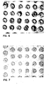
- Fig. 7 is a micrograph in a view taken from the top of a glass-ceramic substrate having a matrix of interlevel via holes each accommodating a copper conductor therein.
- the ceramic is formed snugly around the copper conductors.
Landscapes
- Engineering & Computer Science (AREA)
- Chemical & Material Sciences (AREA)
- Ceramic Engineering (AREA)
- Manufacturing & Machinery (AREA)
- Materials Engineering (AREA)
- Structural Engineering (AREA)
- Organic Chemistry (AREA)
- Inorganic Chemistry (AREA)
- Mechanical Engineering (AREA)
- General Physics & Mathematics (AREA)
- Computer Hardware Design (AREA)
- Microelectronics & Electronic Packaging (AREA)
- Power Engineering (AREA)
- Condensed Matter Physics & Semiconductors (AREA)
- Physics & Mathematics (AREA)
- Production Of Multi-Layered Print Wiring Board (AREA)
- Conductive Materials (AREA)
- Powder Metallurgy (AREA)
- Parts Printed On Printed Circuit Boards (AREA)
Applications Claiming Priority (2)
| Application Number | Priority Date | Filing Date | Title |
|---|---|---|---|
| US06/604,259 US4671928A (en) | 1984-04-26 | 1984-04-26 | Method of controlling the sintering of metal particles |
| US604259 | 1984-04-26 |
Publications (3)
| Publication Number | Publication Date |
|---|---|
| EP0159690A2 true EP0159690A2 (de) | 1985-10-30 |
| EP0159690A3 EP0159690A3 (en) | 1987-10-21 |
| EP0159690B1 EP0159690B1 (de) | 1990-03-28 |
Family
ID=24418876
Family Applications (1)
| Application Number | Title | Priority Date | Filing Date |
|---|---|---|---|
| EP85104885A Expired EP0159690B1 (de) | 1984-04-26 | 1985-04-23 | Verfahren zum Kontrollieren des Sinterns von Metallpulvern |
Country Status (4)
| Country | Link |
|---|---|
| US (1) | US4671928A (de) |
| EP (1) | EP0159690B1 (de) |
| JP (1) | JPS60230946A (de) |
| DE (1) | DE3576793D1 (de) |
Cited By (2)
| Publication number | Priority date | Publication date | Assignee | Title |
|---|---|---|---|---|
| EP0267602A2 (de) * | 1986-11-12 | 1988-05-18 | International Business Machines Corporation | Verfahren zur Herstellung einer Mehrschichtstruktur hoher Dichte aus Glaskeramik mit metallischen Leitern |
| EP0595745A2 (de) * | 1992-10-28 | 1994-05-04 | International Business Machines Corporation | Verfahren zur Kontrolle des Verdichtungsverhaltens eines metallischen Anteils in einem keramischen Material |
Families Citing this family (16)
| Publication number | Priority date | Publication date | Assignee | Title |
|---|---|---|---|---|
| JPS6248097A (ja) * | 1985-08-28 | 1987-03-02 | 日本特殊陶業株式会社 | 多層回路基板の製造法 |
| US4885038A (en) * | 1986-05-01 | 1989-12-05 | International Business Machines Corporation | Method of making multilayered ceramic structures having an internal distribution of copper-based conductors |
| US4906514A (en) * | 1988-11-21 | 1990-03-06 | Corning Incorporated | Metallized substrate for electronic device |
| JPH02152105A (ja) * | 1988-12-01 | 1990-06-12 | Fujitsu Ltd | 導電材料およびその製造方法 |
| US4954313A (en) * | 1989-02-03 | 1990-09-04 | Amdahl Corporation | Method and apparatus for filling high density vias |
| JP2992380B2 (ja) * | 1991-08-27 | 1999-12-20 | 日本特殊陶業株式会社 | ビアホールメタライズを有するセラミック焼結体の製造方法 |
| JPH05218654A (ja) * | 1991-10-25 | 1993-08-27 | Internatl Business Mach Corp <Ibm> | マイクロ波を用いたセラミック複合構造の製造方法 |
| JPH06223623A (ja) * | 1992-12-28 | 1994-08-12 | Internatl Business Mach Corp <Ibm> | 銅を素材とするペーストおよびセラミックパッケージ |
| US5543173A (en) * | 1993-10-12 | 1996-08-06 | Aluminum Company Of America | Surface treating aluminum trihydrate powders with prehydrolized silane |
| US5348760A (en) * | 1993-10-12 | 1994-09-20 | Aluminum Company Of America | Surface treated ceramic powders |
| DE19781541B4 (de) * | 1996-11-27 | 2006-10-05 | The Furukawa Electric Co., Ltd. | Vorrichtung aus einem III-V-Verbindungshalbleiter und Verfahren zur Herstellung der Vorrichtung |
| JP3807257B2 (ja) * | 2001-06-25 | 2006-08-09 | 松下電器産業株式会社 | セラミック部品の製造方法 |
| JP2006117959A (ja) * | 2004-10-19 | 2006-05-11 | Fukuda Metal Foil & Powder Co Ltd | 電子材料用銅粉 |
| DE102006047928A1 (de) * | 2006-10-10 | 2008-04-17 | Robert Bosch Gmbh | Verfahren zur Herstellung mindestens einer porösen Schicht |
| KR102105402B1 (ko) * | 2014-01-08 | 2020-04-29 | 삼성전기주식회사 | 다층 세라믹 기판 및 제조 방법 |
| US9976058B2 (en) * | 2015-05-29 | 2018-05-22 | Palo Alto Research Center Incorporated | High temperature seal compositions and methods of using same |
Citations (3)
| Publication number | Priority date | Publication date | Assignee | Title |
|---|---|---|---|---|
| DE1665857A1 (de) * | 1967-01-27 | 1971-04-15 | Siemens Ag | Verfahren zum Herstellen von festhaftenden loetfaehigen Metallueberzuegen auf Keramikteilen |
| US4186244A (en) * | 1977-05-03 | 1980-01-29 | Graham Magnetics Inc. | Novel silver powder composition |
| US4234367A (en) * | 1979-03-23 | 1980-11-18 | International Business Machines Corporation | Method of making multilayered glass-ceramic structures having an internal distribution of copper-based conductors |
Family Cites Families (19)
| Publication number | Priority date | Publication date | Assignee | Title |
|---|---|---|---|---|
| DE1483266A1 (de) * | 1964-08-10 | 1970-01-08 | Minnesota Mining & Mfg | Metallfabrikation |
| US3266893A (en) * | 1965-06-17 | 1966-08-16 | Electric Storage Battery Co | Method for manufacturing porous sinterable articles |
| US3341325A (en) * | 1966-12-09 | 1967-09-12 | Crucible Steel Co America | Method for producing alloy-steel articles |
| CH462473A (fr) * | 1967-08-18 | 1968-09-15 | Suisse De Rech S Horlogeres La | Procédé de préparation d'un produit solide |
| JPS5428976B2 (de) * | 1973-09-21 | 1979-09-20 | ||
| JPS5335768B2 (de) * | 1973-09-21 | 1978-09-28 | ||
| JPS5253720A (en) * | 1975-10-29 | 1977-04-30 | Hitachi Ltd | Non-orientated cu-carbon fiber compoite and its manufacturing method |
| US4109377A (en) * | 1976-02-03 | 1978-08-29 | International Business Machines Corporation | Method for preparing a multilayer ceramic |
| US4289719A (en) * | 1976-12-10 | 1981-09-15 | International Business Machines Corporation | Method of making a multi-layer ceramic substrate |
| US4431449A (en) * | 1977-09-26 | 1984-02-14 | Minnesota Mining And Manufacturing Company | Infiltrated molded articles of spherical non-refractory metal powders |
| SE427434B (sv) * | 1980-03-06 | 1983-04-11 | Hoeganaes Ab | Jernbaserad pulverblandning med tillsats mot avblandning och/eller damning |
| JPS5735561A (en) * | 1980-08-13 | 1982-02-26 | Sumitomo Chem Co Ltd | Novel alpha- mercaptomethyl acrylic acid derivative |
| JPS5735601A (en) * | 1980-08-13 | 1982-02-26 | Daido Steel Co Ltd | Sintering and forging method |
| JPS5761026A (en) * | 1980-10-01 | 1982-04-13 | Toshiba Corp | Production of conductive plastic molding |
| SU929722A1 (ru) * | 1980-10-10 | 1982-05-23 | Московский Ордена Трудового Красного Знамени Институт Стали И Сплавов | Способ пассивации восстановленной железной руды |
| US4434134A (en) * | 1981-04-10 | 1984-02-28 | International Business Machines Corporation | Pinned ceramic substrate |
| JPS57208195A (en) * | 1981-06-17 | 1982-12-21 | Hitachi Ltd | Conductive paste for green sheet |
| JPS60215589A (ja) * | 1984-04-11 | 1985-10-28 | 松下電器産業株式会社 | セラミツク生シ−トの貫通孔内部を金属化する方法 |
| JPS6126A (ja) * | 1984-06-08 | 1986-01-06 | Mitsui Petrochem Ind Ltd | イソブチレンの製造方法 |
-
1984
- 1984-04-26 US US06/604,259 patent/US4671928A/en not_active Expired - Fee Related
- 1984-12-20 JP JP59267636A patent/JPS60230946A/ja active Granted
-
1985
- 1985-04-23 DE DE8585104885T patent/DE3576793D1/de not_active Expired - Fee Related
- 1985-04-23 EP EP85104885A patent/EP0159690B1/de not_active Expired
Patent Citations (3)
| Publication number | Priority date | Publication date | Assignee | Title |
|---|---|---|---|---|
| DE1665857A1 (de) * | 1967-01-27 | 1971-04-15 | Siemens Ag | Verfahren zum Herstellen von festhaftenden loetfaehigen Metallueberzuegen auf Keramikteilen |
| US4186244A (en) * | 1977-05-03 | 1980-01-29 | Graham Magnetics Inc. | Novel silver powder composition |
| US4234367A (en) * | 1979-03-23 | 1980-11-18 | International Business Machines Corporation | Method of making multilayered glass-ceramic structures having an internal distribution of copper-based conductors |
Cited By (4)
| Publication number | Priority date | Publication date | Assignee | Title |
|---|---|---|---|---|
| EP0267602A2 (de) * | 1986-11-12 | 1988-05-18 | International Business Machines Corporation | Verfahren zur Herstellung einer Mehrschichtstruktur hoher Dichte aus Glaskeramik mit metallischen Leitern |
| EP0267602A3 (de) * | 1986-11-12 | 1990-08-01 | International Business Machines Corporation | Verfahren zur Herstellung einer Mehrschichtstruktur hoher Dichte aus Glaskeramik mit metallischen Leitern |
| EP0595745A2 (de) * | 1992-10-28 | 1994-05-04 | International Business Machines Corporation | Verfahren zur Kontrolle des Verdichtungsverhaltens eines metallischen Anteils in einem keramischen Material |
| EP0595745A3 (de) * | 1992-10-28 | 1994-11-23 | Ibm | Verfahren zur Kontrolle des Verdichtungsverhaltens eines metallischen Anteils in einem keramischen Material. |
Also Published As
| Publication number | Publication date |
|---|---|
| US4671928A (en) | 1987-06-09 |
| EP0159690B1 (de) | 1990-03-28 |
| JPH0577197B2 (de) | 1993-10-26 |
| EP0159690A3 (en) | 1987-10-21 |
| DE3576793D1 (de) | 1990-05-03 |
| JPS60230946A (ja) | 1985-11-16 |
Similar Documents
| Publication | Publication Date | Title |
|---|---|---|
| EP0159690B1 (de) | Verfahren zum Kontrollieren des Sinterns von Metallpulvern | |
| CA1222832A (en) | Method for removal of carbonaceous residues from ceramic structures having internal metallurgy | |
| EP0275052B1 (de) | Verfahren zur Herstellung eines keramischen Mehrschichtkörpers mit inneren Kupferteilen | |
| US4234367A (en) | Method of making multilayered glass-ceramic structures having an internal distribution of copper-based conductors | |
| US5370759A (en) | Method for producing multilayered ceramic substrate | |
| US5004640A (en) | Multilayered ceramic substrates and method for manufacturing the same | |
| US4795512A (en) | Method of manufacturing a multilayer ceramic body | |
| US3838204A (en) | Multilayer circuits | |
| US5073180A (en) | Method for forming sealed co-fired glass ceramic structures | |
| JPH05102666A (ja) | 多層セラミツク基板の製造方法 | |
| US5062891A (en) | Metallic inks for co-sintering process | |
| US4776978A (en) | Method of controlling the sintering of metal particles | |
| JP3467872B2 (ja) | 多層セラミック基板の製造方法 | |
| US5147484A (en) | Method for producing multi-layer ceramic substrates with oxidation resistant metalization | |
| JP3351043B2 (ja) | 多層セラミック基板の製造方法 | |
| JP3467873B2 (ja) | 多層セラミック基板の製造方法 | |
| JP2803414B2 (ja) | 多層セラミック基板の製造方法 | |
| JPH06223621A (ja) | 導体ペースト組成物 | |
| EP0312824A2 (de) | Keramische Struktur mit Kupferleiter und Verfahren zum Herstellen solcher Struktur | |
| US3585460A (en) | Miniature ceramic capacitor and method of manufacture | |
| JPH1116419A (ja) | 導電性ペースト及びこれを用いたセラミックス多層基板の製造方法 | |
| JPH05308193A (ja) | 多層セラミック基板の製造方法 | |
| JPS6077187A (ja) | セラミツク電子部品及びその製造法 | |
| JPH07105306B2 (ja) | 積層セラミックコンデンサの製造方法 | |
| JPS61292392A (ja) | セラミツク配線基板の製造方法 |
Legal Events
| Date | Code | Title | Description |
|---|---|---|---|
| PUAI | Public reference made under article 153(3) epc to a published international application that has entered the european phase |
Free format text: ORIGINAL CODE: 0009012 |
|
| AK | Designated contracting states |
Designated state(s): DE FR GB |
|
| 17P | Request for examination filed |
Effective date: 19860225 |
|
| PUAL | Search report despatched |
Free format text: ORIGINAL CODE: 0009013 |
|
| AK | Designated contracting states |
Kind code of ref document: A3 Designated state(s): DE FR GB |
|
| 17Q | First examination report despatched |
Effective date: 19881104 |
|
| GRAA | (expected) grant |
Free format text: ORIGINAL CODE: 0009210 |
|
| AK | Designated contracting states |
Kind code of ref document: B1 Designated state(s): DE FR GB |
|
| REF | Corresponds to: |
Ref document number: 3576793 Country of ref document: DE Date of ref document: 19900503 |
|
| ET | Fr: translation filed | ||
| PLBE | No opposition filed within time limit |
Free format text: ORIGINAL CODE: 0009261 |
|
| STAA | Information on the status of an ep patent application or granted ep patent |
Free format text: STATUS: NO OPPOSITION FILED WITHIN TIME LIMIT |
|
| 26N | No opposition filed | ||
| PGFP | Annual fee paid to national office [announced via postgrant information from national office to epo] |
Ref country code: FR Payment date: 19950328 Year of fee payment: 11 |
|
| PGFP | Annual fee paid to national office [announced via postgrant information from national office to epo] |
Ref country code: DE Payment date: 19950428 Year of fee payment: 11 |
|
| PGFP | Annual fee paid to national office [announced via postgrant information from national office to epo] |
Ref country code: GB Payment date: 19960325 Year of fee payment: 12 |
|
| PG25 | Lapsed in a contracting state [announced via postgrant information from national office to epo] |
Ref country code: FR Effective date: 19961227 |
|
| PG25 | Lapsed in a contracting state [announced via postgrant information from national office to epo] |
Ref country code: DE Effective date: 19970101 |
|
| REG | Reference to a national code |
Ref country code: FR Ref legal event code: ST |
|
| PG25 | Lapsed in a contracting state [announced via postgrant information from national office to epo] |
Ref country code: GB Effective date: 19970423 |
|
| GBPC | Gb: european patent ceased through non-payment of renewal fee |
Effective date: 19970423 |