EP0595745A2 - Verfahren zur Kontrolle des Verdichtungsverhaltens eines metallischen Anteils in einem keramischen Material - Google Patents
Verfahren zur Kontrolle des Verdichtungsverhaltens eines metallischen Anteils in einem keramischen Material Download PDFInfo
- Publication number
- EP0595745A2 EP0595745A2 EP93480128A EP93480128A EP0595745A2 EP 0595745 A2 EP0595745 A2 EP 0595745A2 EP 93480128 A EP93480128 A EP 93480128A EP 93480128 A EP93480128 A EP 93480128A EP 0595745 A2 EP0595745 A2 EP 0595745A2
- Authority
- EP
- European Patent Office
- Prior art keywords
- ceramic material
- sintering
- metallic feature
- metallic
- carbonaceous
- Prior art date
- Legal status (The legal status is an assumption and is not a legal conclusion. Google has not performed a legal analysis and makes no representation as to the accuracy of the status listed.)
- Withdrawn
Links
- 229910010293 ceramic material Inorganic materials 0.000 title claims abstract description 76
- 238000000034 method Methods 0.000 title claims abstract description 34
- 238000000280 densification Methods 0.000 title claims abstract description 22
- 238000005245 sintering Methods 0.000 claims abstract description 99
- 239000003575 carbonaceous material Substances 0.000 claims abstract description 25
- 230000001590 oxidative effect Effects 0.000 claims abstract description 19
- 238000010438 heat treatment Methods 0.000 claims abstract description 8
- 239000012298 atmosphere Substances 0.000 claims description 34
- 239000000919 ceramic Substances 0.000 claims description 32
- 239000002245 particle Substances 0.000 claims description 18
- OKTJSMMVPCPJKN-UHFFFAOYSA-N Carbon Chemical compound [C] OKTJSMMVPCPJKN-UHFFFAOYSA-N 0.000 claims description 17
- 238000000197 pyrolysis Methods 0.000 claims description 15
- 239000000463 material Substances 0.000 claims description 14
- 239000011159 matrix material Substances 0.000 claims description 12
- PNEYBMLMFCGWSK-UHFFFAOYSA-N aluminium oxide Inorganic materials [O-2].[O-2].[O-2].[Al+3].[Al+3] PNEYBMLMFCGWSK-UHFFFAOYSA-N 0.000 claims description 6
- 239000006229 carbon black Substances 0.000 claims description 3
- 150000001875 compounds Chemical class 0.000 claims description 3
- 229910002804 graphite Inorganic materials 0.000 claims description 2
- 239000010439 graphite Substances 0.000 claims description 2
- 239000007769 metal material Substances 0.000 claims description 2
- 239000013528 metallic particle Substances 0.000 claims description 2
- 238000005457 optimization Methods 0.000 abstract description 4
- 230000002411 adverse Effects 0.000 abstract description 2
- 238000012512 characterization method Methods 0.000 abstract description 2
- 239000011230 binding agent Substances 0.000 description 28
- 229910052802 copper Inorganic materials 0.000 description 20
- 239000010949 copper Substances 0.000 description 20
- RYGMFSIKBFXOCR-UHFFFAOYSA-N Copper Chemical compound [Cu] RYGMFSIKBFXOCR-UHFFFAOYSA-N 0.000 description 18
- 239000003112 inhibitor Substances 0.000 description 13
- 229910052799 carbon Inorganic materials 0.000 description 12
- 229910052751 metal Inorganic materials 0.000 description 12
- 239000002184 metal Substances 0.000 description 12
- 239000000758 substrate Substances 0.000 description 11
- 239000002131 composite material Substances 0.000 description 7
- 239000006112 glass ceramic composition Substances 0.000 description 6
- 230000002829 reductive effect Effects 0.000 description 6
- 238000009792 diffusion process Methods 0.000 description 5
- IJGRMHOSHXDMSA-UHFFFAOYSA-N Atomic nitrogen Chemical compound N#N IJGRMHOSHXDMSA-UHFFFAOYSA-N 0.000 description 4
- UFHFLCQGNIYNRP-UHFFFAOYSA-N Hydrogen Chemical compound [H][H] UFHFLCQGNIYNRP-UHFFFAOYSA-N 0.000 description 4
- ZOKXTWBITQBERF-UHFFFAOYSA-N Molybdenum Chemical compound [Mo] ZOKXTWBITQBERF-UHFFFAOYSA-N 0.000 description 4
- 239000011521 glass Substances 0.000 description 4
- 239000001257 hydrogen Substances 0.000 description 4
- 229910052739 hydrogen Inorganic materials 0.000 description 4
- 230000007246 mechanism Effects 0.000 description 4
- 239000002923 metal particle Substances 0.000 description 4
- 229910052750 molybdenum Inorganic materials 0.000 description 4
- 239000011733 molybdenum Substances 0.000 description 4
- 239000007789 gas Substances 0.000 description 3
- PCHJSUWPFVWCPO-UHFFFAOYSA-N gold Chemical compound [Au] PCHJSUWPFVWCPO-UHFFFAOYSA-N 0.000 description 3
- 229910052737 gold Inorganic materials 0.000 description 3
- 239000010931 gold Substances 0.000 description 3
- 239000007787 solid Substances 0.000 description 3
- UGFAIRIUMAVXCW-UHFFFAOYSA-N Carbon monoxide Chemical compound [O+]#[C-] UGFAIRIUMAVXCW-UHFFFAOYSA-N 0.000 description 2
- KDLHZDBZIXYQEI-UHFFFAOYSA-N Palladium Chemical compound [Pd] KDLHZDBZIXYQEI-UHFFFAOYSA-N 0.000 description 2
- BQCADISMDOOEFD-UHFFFAOYSA-N Silver Chemical compound [Ag] BQCADISMDOOEFD-UHFFFAOYSA-N 0.000 description 2
- 238000004458 analytical method Methods 0.000 description 2
- 239000013590 bulk material Substances 0.000 description 2
- 229910002091 carbon monoxide Inorganic materials 0.000 description 2
- 239000011248 coating agent Substances 0.000 description 2
- 238000000576 coating method Methods 0.000 description 2
- -1 copper aluminate Chemical class 0.000 description 2
- 229910052878 cordierite Inorganic materials 0.000 description 2
- JSKIRARMQDRGJZ-UHFFFAOYSA-N dimagnesium dioxido-bis[(1-oxido-3-oxo-2,4,6,8,9-pentaoxa-1,3-disila-5,7-dialuminabicyclo[3.3.1]nonan-7-yl)oxy]silane Chemical compound [Mg++].[Mg++].[O-][Si]([O-])(O[Al]1O[Al]2O[Si](=O)O[Si]([O-])(O1)O2)O[Al]1O[Al]2O[Si](=O)O[Si]([O-])(O1)O2 JSKIRARMQDRGJZ-UHFFFAOYSA-N 0.000 description 2
- 230000002401 inhibitory effect Effects 0.000 description 2
- 238000002844 melting Methods 0.000 description 2
- 230000008018 melting Effects 0.000 description 2
- 239000000203 mixture Substances 0.000 description 2
- 229910052757 nitrogen Inorganic materials 0.000 description 2
- 239000011368 organic material Substances 0.000 description 2
- 230000000704 physical effect Effects 0.000 description 2
- 239000004014 plasticizer Substances 0.000 description 2
- 229910052709 silver Inorganic materials 0.000 description 2
- 239000004332 silver Substances 0.000 description 2
- 239000002904 solvent Substances 0.000 description 2
- 239000001856 Ethyl cellulose Substances 0.000 description 1
- ZZSNKZQZMQGXPY-UHFFFAOYSA-N Ethyl cellulose Chemical compound CCOCC1OC(OC)C(OCC)C(OCC)C1OC1C(O)C(O)C(OC)C(CO)O1 ZZSNKZQZMQGXPY-UHFFFAOYSA-N 0.000 description 1
- VYPSYNLAJGMNEJ-UHFFFAOYSA-N Silicium dioxide Chemical compound O=[Si]=O VYPSYNLAJGMNEJ-UHFFFAOYSA-N 0.000 description 1
- 239000000654 additive Substances 0.000 description 1
- CNLWCVNCHLKFHK-UHFFFAOYSA-N aluminum;lithium;dioxido(oxo)silane Chemical compound [Li+].[Al+3].[O-][Si]([O-])=O.[O-][Si]([O-])=O CNLWCVNCHLKFHK-UHFFFAOYSA-N 0.000 description 1
- 229910052661 anorthite Inorganic materials 0.000 description 1
- 238000013459 approach Methods 0.000 description 1
- 239000005388 borosilicate glass Substances 0.000 description 1
- 239000003795 chemical substances by application Substances 0.000 description 1
- 239000004020 conductor Substances 0.000 description 1
- 238000000151 deposition Methods 0.000 description 1
- 238000004031 devitrification Methods 0.000 description 1
- GWWPLLOVYSCJIO-UHFFFAOYSA-N dialuminum;calcium;disilicate Chemical compound [Al+3].[Al+3].[Ca+2].[O-][Si]([O-])([O-])[O-].[O-][Si]([O-])([O-])[O-] GWWPLLOVYSCJIO-UHFFFAOYSA-N 0.000 description 1
- KZHJGOXRZJKJNY-UHFFFAOYSA-N dioxosilane;oxo(oxoalumanyloxy)alumane Chemical compound O=[Si]=O.O=[Si]=O.O=[Al]O[Al]=O.O=[Al]O[Al]=O.O=[Al]O[Al]=O KZHJGOXRZJKJNY-UHFFFAOYSA-N 0.000 description 1
- 229920001249 ethyl cellulose Polymers 0.000 description 1
- 235000019325 ethyl cellulose Nutrition 0.000 description 1
- 229910000174 eucryptite Inorganic materials 0.000 description 1
- 229910021485 fumed silica Inorganic materials 0.000 description 1
- 239000002241 glass-ceramic Substances 0.000 description 1
- 150000001247 metal acetylides Chemical class 0.000 description 1
- 238000012986 modification Methods 0.000 description 1
- 230000004048 modification Effects 0.000 description 1
- 229910052863 mullite Inorganic materials 0.000 description 1
- 239000012299 nitrogen atmosphere Substances 0.000 description 1
- 239000006259 organic additive Substances 0.000 description 1
- 239000003960 organic solvent Substances 0.000 description 1
- 150000002902 organometallic compounds Chemical class 0.000 description 1
- 230000003647 oxidation Effects 0.000 description 1
- 238000007254 oxidation reaction Methods 0.000 description 1
- TWNQGVIAIRXVLR-UHFFFAOYSA-N oxo(oxoalumanyloxy)alumane Chemical compound O=[Al]O[Al]=O TWNQGVIAIRXVLR-UHFFFAOYSA-N 0.000 description 1
- 238000004806 packaging method and process Methods 0.000 description 1
- 229910052763 palladium Inorganic materials 0.000 description 1
- 230000036961 partial effect Effects 0.000 description 1
- 239000008188 pellet Substances 0.000 description 1
- 239000011148 porous material Substances 0.000 description 1
- 239000000376 reactant Substances 0.000 description 1
- 239000011214 refractory ceramic Substances 0.000 description 1
- 239000004065 semiconductor Substances 0.000 description 1
- HBMJWWWQQXIZIP-UHFFFAOYSA-N silicon carbide Chemical compound [Si+]#[C-] HBMJWWWQQXIZIP-UHFFFAOYSA-N 0.000 description 1
- 229910010271 silicon carbide Inorganic materials 0.000 description 1
- 229910052642 spodumene Inorganic materials 0.000 description 1
- 230000006641 stabilisation Effects 0.000 description 1
- 238000011105 stabilization Methods 0.000 description 1
- WFKWXMTUELFFGS-UHFFFAOYSA-N tungsten Chemical compound [W] WFKWXMTUELFFGS-UHFFFAOYSA-N 0.000 description 1
- 229910052721 tungsten Inorganic materials 0.000 description 1
- 239000010937 tungsten Substances 0.000 description 1
Images
Classifications
-
- C—CHEMISTRY; METALLURGY
- C04—CEMENTS; CONCRETE; ARTIFICIAL STONE; CERAMICS; REFRACTORIES
- C04B—LIME, MAGNESIA; SLAG; CEMENTS; COMPOSITIONS THEREOF, e.g. MORTARS, CONCRETE OR LIKE BUILDING MATERIALS; ARTIFICIAL STONE; CERAMICS; REFRACTORIES; TREATMENT OF NATURAL STONE
- C04B35/00—Shaped ceramic products characterised by their composition; Ceramics compositions; Processing powders of inorganic compounds preparatory to the manufacturing of ceramic products
- C04B35/71—Ceramic products containing macroscopic reinforcing agents
- C04B35/74—Ceramic products containing macroscopic reinforcing agents containing shaped metallic materials
-
- C—CHEMISTRY; METALLURGY
- C04—CEMENTS; CONCRETE; ARTIFICIAL STONE; CERAMICS; REFRACTORIES
- C04B—LIME, MAGNESIA; SLAG; CEMENTS; COMPOSITIONS THEREOF, e.g. MORTARS, CONCRETE OR LIKE BUILDING MATERIALS; ARTIFICIAL STONE; CERAMICS; REFRACTORIES; TREATMENT OF NATURAL STONE
- C04B38/00—Porous mortars, concrete, artificial stone or ceramic ware; Preparation thereof
- C04B38/06—Porous mortars, concrete, artificial stone or ceramic ware; Preparation thereof by burning-out added substances by burning natural expanding materials or by sublimating or melting out added substances
- C04B38/063—Preparing or treating the raw materials individually or as batches
- C04B38/0635—Compounding ingredients
- C04B38/0645—Burnable, meltable, sublimable materials
- C04B38/068—Carbonaceous materials, e.g. coal, carbon, graphite, hydrocarbons
Definitions
- the present invention generally relates to metallic features in bulk ceramic materials and, more particularly, to a method of controlling the densification behavior of the metallic feature in the ceramic material by incorporating in the metallic feature an amount of carbonaceous material which inhibits the sintering of the metallic feature.
- metal particles, such as copper, in the via paste undergo sintering with attendant shrinkage of the thick film pattern (also consisting of the paste) during the initial phase of the sintering cycle whereas the ceramic and glass particles (of the ceramic substrate containing the vias) undergo sintering during the intermediate and final phases of the sintering cycle along with their characteristic shrinkage.
- One method of delaying the onset of sintering of the metal particles until at least the intermediate phase of the sintering cycle is to intersperse the metal particles in the thick film with a high melting point material such as aluminum oxide.
- Herron et al. US-A-4,671,928 teaches the coating of copper particles with an organic material.
- the coated copper particles are incorporated in a paste and cofired With the ceramic bulk material.
- the coating on the copper particles is pyrolyzed to a carbonaceous residue during the pyrolysis stage of the sintering cycle.
- the carbonaceous residue retards the sintering of the copper particles so that they do not begin to densify until the binder burnoff stage of the sintering cycle when an oxidizing ambient is introduced which removes the carbonaceous residue.
- the copper particles can easily densify. In fact, the copper particles will have densified before the ceramic material sinters.
- Siuta US-A-4,594,181 teaches the dispersal of copper particles in a solution of an organometallic compound in an anhydrous volatile organic solvent towards obtaining a better shrinkage match of copper to ceramic substrates during sintering.
- Beil US-A-4,020,206 discloses a thick film paste for vias which consists of gold particles, glass binder and refractory particles.
- the refractory particles are metallic carbides such as silicon carbide.
- the purpose of the refractory particles is that since they do not melt at the sintering temperature of the gold paste, they serve to reduce the volumetric shrinkage of the vias to less than 5%.
- Reed US-A-4,964,948 discloses generally a conductive ink consisting of silver flakes, carbon black and fumed silica.
- a purpose of the present invention is to have a method of sintering a composite structure comprising metallic features in a ceramic material wherein the metallic features have reduced shrinkage during the sintering of the ceramic material.
- Another purpose of the present invention is to have a method of sintering a composite structure comprising metallic features in a porous ceramic material wherein the metallic features have educed shrinkage (or no shrinkage) during the sintering of the low shrinkage (or no shrinkage) porous ceramic material, and where metallic shrinkage can subsequently be promoted post stabilization of the porous ceramic material for optimization of electrical conductivity of the metallic component.
- the purposes of the invention have been achieved by providing a method of controlling the densification behavior of a metallic feature in a ceramic material, the method comprising the steps of: obtaining an unsintered ceramic material having at least one metallic feature therein; providing at least the metallic feature with a predetermined amount of carbonaceous material; heating the ceramic material and metallic feature to a predetermined temperature sufficient to cause sintering of the ceramic material, the metallic feature being at least partially inhibited from densifying at the predetermined temperature by the presence of the carbonaceous material.
- a key aspect of the invention is subsequently removing with an oxidizing ambient some or all of the carbonaceous residue at a predetermined temperature for the optimization of the physical characterization of the fired metallic component in ceramic material without adversely affecting distortion and alignment of the metallic feature.
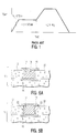
- FIG. 1 is a prior art sintering profile.
- FIGS. 2 to 4 are sintering profiles useful with the method according to the present invention.
- FIGS. 5A and 5B are partial cross-sectional views of a preferred embodiment of the invention.
- FIG. 5A illustrates the ceramic material after it has sintered but before the metallic feature has sintered while
- FIG. 5B illustrates the final structure after the metallic feature has sintered.
- All unsintered (i.e., green) ceramic materials are processed through a sintering cycle to remove the binder materials that hold the ceramic particles together in the unsintered state and to cause the sintering of the ceramic particles.
- Sintering occurs at temperatures much higher than that necessary to remove the bulk binder material and any other organics present by pyrolysis and volatilization.
- the step of sintering, per se, is the removal of surface area, usually through diffusion mechanisms. It is necessary for neck growth to occur between adjacent ceramic particles in order for sintering to proceed.
- a typical sintering cycle consists of a pyrolysis stage where the organic binder material and any other organic materials present are removed by pyrolysis and volatilization. Inevitably, some amount of carbonaceous residue is left behind. Thereafter, the temperature is raised to a higher temperature in a suitable atmosphere to remove the carbonaceous residue and subsequently allow for sintering of the ceramic bulk material as well as any metallic features that are present.
- FIG. 1 Such a prior art sintering cycle is illustrated in FIG. 1.
- the composite structure consisting of the ceramic material and the metallic features first undergoes pyrolysis in a wet nitrogen atmosphere where the polymeric binders of the ceramic material and the metallic features, as well as other organics such as plasticizers, solvents, etc., are pyrolyzed to a carbonaceous residue. After the temperature has been ramped up for pyrolysis, the atmosphere is changed to wet hydrogen and the composite structure is held at that temperature in order for the carbon residue to be burned off. The mechanism is quite well known.
- the carbonaceous residues combine with steam to form hydrogen and carbon monoxide gas which escape from the composite structure.
- binder burnoff very little or no carbon is left.
- the atmosphere is changed to an inert or reducing atmosphere and the temperature is ramped to still higher temperatures wherein the sintering of the ceramic material occurs.
- the metallic feature may have undergone sintering at a much earlier temperature, resulting in a shrinkage differential between the ceramic material and the metallic feature.
- the present inventors have discovered that if the metallic features contain some carbonaceous material past binder burnoff and up through the time when the ceramic material is sintered, i.e., until such time as the ceramic material has achieved its strength characteristics, the metallic features are at least partially inhibited from sintering.
- the degree to which the metallic features are inhibited from sintering will depend upon the amount of carbonaceous material present.
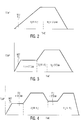
- FIG. 2 there is shown a sintering cycle useful with the present invention.
- the composite structure undergoes pyrolysis in a slightly oxidizing atmosphere such as wet nitrogen (i.e., N2 plus steam).
- a slightly oxidizing atmosphere such as wet nitrogen (i.e., N2 plus steam).
- the atmosphere is switched to a non-oxidizing atmosphere such as H2 in N2 and the temperature is ramped up through the temperature range in which the ceramic will sinter.
- the ceramic material and the metallic feature may undergo sintering but with limited mismatched densification due to the presence of the carbon residue. It is, therefore, useful in this embodiment of the invention for the ceramic to contain some interconnected porosity so that after sintering, any residual carbon can be removed from the ceramic.
- a unique aspect of the present invention is that after the carbonaceous matter has performed its function of inhibiting the sintering of the metallic features, all or part of the carbonaceous matter is removed.
- the sintering inhibitor according to the present invention can be fugitive in nature which is advantageous since there will be a reduced permanent foreign component in the metallic features, once they have been fully sintered. This process of removing the carbon after its usefulness has been exhausted can be tailored such that the physical and electrical properties of the metallic features are optimized.
- the porosity may be achieved by any number of known means.
- One method for purposes of illustration and not limitation, is to use a sintering retardant which retards the extent to which sintering is achieved in the ceramic material.
- a common sintering retardant is one which has a higher sintering temperature than the ceramic material.
- One such combination would be alumina in a glass ceramic material.
- a porous ceramic can be defined as one which has a density after sintering of less than 90% of theoretical.
- an alternative sintering cycle may be utilized.
- the composite structure of ceramic material and metallic features first undergoes pyrolysis in a slightly oxidizing atmosphere as before. Now, however, the temperature is held after pyrolysis for a period of time for binder burnoff to occur.
- binder proceeds to completion so that substantially all the carbonaceous residues are removed.
- metallic features some carbonacecus matter remains after binder burnoff. This may be accomplished in several ways, two examples of which follow.
- the first example is that the metallic features comprise, in addition to the polymeric matrix, a carbonaceous material such as graphite or carbon black which at least partially remains after binder burnoff even though the polymeric matrix may be burned off.
- the second example is to choose two different polymeric materials for the binders wherein the polymeric material of the ceramic material matrix pyrolizes more cleanly than the polymeric material of the metallic features matrix so that after binder burnoff, some carbonaceous residue remains among the metallic particles to inhibit their sintering.
- the atmosphere is changed to a non-oxidizing atmosphere and the temperature is ramped up through the temperature range in which the ceramic material will sinter.
- the ceramic material is allowed to sinter in this non-oxidizing ambient while the carbonaceous matter in the metallic features inhibits the sintering of the metallic features so as to closely match the densification behavior of the ceramic up to and including possible no shrink conditions.
- the atmosphere can be changed to an oxidizing atmosphere and some or all of the remaining carbonaceous matter in the metallic features can be removed. While maintaining the same sintering temperature, the metallic features will then undergo additional sintering and potentially additional densification such that physical properties of the fired conductor are improved as before.
- the ceramic for this embodiment of the invention may be porous or non-porous. Porous ceramic is somewhat preferred as it will facilitate the removal of the hydrogen and carbon monoxide product gases resulting from the final burnoff of the carbonaceous matter in the metallic features by pore diffusion.
- FIG. 4 Another sintering profile useful for the present invention is illustrated in FIG. 4. This profile is identical in nature to FIG. 3 up to the sintering of the ceramic material to high temperature. However, in this case, now the temperature is reduced back down to binder burnoff temperature range and the atmosphere is changed to an oxidizing ambient such as wet hydrogen. This segment is essentially a second binder burnoff. After the carbonaceous residues are removed, the atmosphere is changed to a non-oxidizing atmosphere and the temperature is ramped up again to that necessary for the sintering of the ceramic material. This time, however, it is the metallic features that undergo densification with concomitant optimization cf their physical properties.
- the ceramic material be porous so that carbonaceous material of the metal particles is accessible through the porous ceramic body to the reactant gas during the second binder burnoff segment of the sintering cycle.
- a second sintering inhibitor in the metallic features.
- a sintering inhibitor might be alumina or an alumina-forming compound such as copper aluminate.
- This second sintering inhibitor is useful for inhibiting the sintering of the metallic features at lower temperatures such as where binder burnoff occurs but at higher temperatures, such as where sintering of the ceramic material occurs, this sintering inhibitor is not very effective.
- the second inhibitor is not effective but there is the presence of carbonaceous matter in the metallic features to prevent the sintering of the metallic features.
- the carbonaceous matter is removed, thereby also removing the inhibitor that prevents the sintering of the metallic features at higher temperatures.
- the presence, however, of the second inhibitor retards any sintering of the metallic features that might take place at this temperature. Once the temperature is again raised to the sintering temperature of the ceramic material, the second inhibitor loses its effectiveness and sintering of the metallic features can proceed.
- the second sintering inhibitor is most desirable when the natural densification temperature of the metal in the metallic feature is below the temperature required to remove carbon.
- the binder burnoff temperature is between about 700 and 800 degrees Centigrade, which is well above the natural densification temperature of copper. It is thus expected that second sintering inhibitor with the copper and the carbonaceous matter would be effective in the sintering profile of FIG. 4.
- the binder burnoff temperature is between about 1000 and 1200 degrees Centigrade which is below the natural densification temperature of molybdenum. It is thus expected that a second sintering inhibitor with the molybdenum and the carbonaceous matter would not be necessary in the sintering profile of FIG. 4.
- FIGS. 5A and 5B A preferred application of the invention is illustrated in FIGS. 5A and 5B.
- a substrate 10 comprises ceramic material 12 and a metallic via 14.
- Capture pads 16 have been applied by decal technology. Decals may be formed by depositing conductive metal lines and pads on a carrier sheet and then photolithographically defining those lines and pads. The decal is then placed on a substrate such as a greensheet and the carrier sheet is removed. The decal is advantageous, among other reasons, because solid metal lines and pads can be formed.
- FIG. 5A shows the substrate 10 after the ceramic material 12 has been sintered but before the via 14 has been sintered. Via 14 has carbonaceous matter 18 present which has prevented the sintering of the via 14. If preferred, ceramic 12 may have porosity 20.
- the via 14 may be sintered.
- the resulting substrate 10 is shown in FIG. 5B. Since pads 16 are solid metal, they do not shrink during sintering. Via 14, however, being a paste initially, undergoes substantial shrinkage during sintering, creating gap 22 between the via 14 and ceramic 12. Via 14 does become pinned at the ends to pads 16, thereby assuring the physical and electrical integrity of the substrate 10. Although a decal was used in this illustration as a capture pad, it could well have been similarly demonstrated with screened lines using paste similar to the via fill paste.
- the invention is believed to be generally applicable to many combinations of ceramic materials and metallic features.
- the ceramic material may be, but not limited to, for example, alumina, mullite, glass plus ceramics such as borosilicate glass that includes ceramic additives, and glass ceramics such as cordierite.
- the metal of the metallic feature may be, but not limited to, palladium, gold, silver or copper in the low fired ceramics and tungsten or molybdenum in the more refractory ceramics.
- the ceramic may be selected from the cordierite and spodumene glass ceramic materials disclosed in Kumar US-A-4,301,324.
- Other glass ceramic materials include, for example, eucryptite and anorthite.
- the preferred metal for the metallic features is copper.
- Glass ceramic materials are a recognized class of materials which begin as glasses but upon heating undergo devitrification and become at least partially crystallized. Some examples are given in Table 1.
- the precise amount of carbonaceous matter in the metallic features will vary depending upon the ceramic and metallic materials. It is known that for the preferred glass ceramic materials with copper metallic features, the carbonaceous matter should be present in the metallic features at the time of sintering of the ceramic in the amount of at least about 1000 to 2500 ppm (parts per million).
- Example I the copper particles were coated with alumina which varied from 0 to 400 ppm.
- Examples II and III contained about 0.5 weight percent of copper aluminate (an alumina-forming compound) based on the total solids content of the sample.
- Example IV contained no additional components. The mixtures were then pressed into pellets and sintered. The results are indicated below.
- a single sample was sintered by ramping up the temperature to about 7200 in an atmosphere of wet N2. Thereafter, the atmosphere was switched to 1 % H2 in N2 and the temperature was ramped up to 975° C for a two hour hold followed by cooldown to room temperature. Although the carbon content was not measured at this point, based on past experience, the sample should have about 1500 ppm of carbon. This sintering cycle was then repeated.
- the sample was determined to have 1000 ppm carbon and a density of 74 of theoretical density after the second sintering cycle. It is believed that this sample had lower carbon content and greater density than Example II samples because the sample of Example III experienced essentially two pyrolysis segments. The pyrolysis segment will cause the removal of some of the carbonaceous residue although it is not nearly as efficient as the binder burnoff segment in removing the carbonaceous residue.
- the single sample in this example was heated by ramping up the temperature to about 450° C in wet N2 followed by cooldown to room temperature.
- the sample was then removed to a dilatometer where the temperature was ramped up to about 9750 C in an atmosphere of 1 % H2 in N2 and held there for two hours, followed by cooldown to room temperature.
- the sample was analyzed and found to have a carbon content of 1376 ppm carbon and a density of 63.7 % of theoretical.
- the density of the sample in the green, unsintered state was 62 % of theoretical density. The data indicates that the presence of the carbon residue resulted in essentially no densification of the sample similar to Example II.
Landscapes
- Chemical & Material Sciences (AREA)
- Engineering & Computer Science (AREA)
- Ceramic Engineering (AREA)
- Materials Engineering (AREA)
- Structural Engineering (AREA)
- Organic Chemistry (AREA)
- Chemical Kinetics & Catalysis (AREA)
- Manufacturing & Machinery (AREA)
- Compositions Of Oxide Ceramics (AREA)
- Production Of Multi-Layered Print Wiring Board (AREA)
- Printing Elements For Providing Electric Connections Between Printed Circuits (AREA)
Applications Claiming Priority (2)
| Application Number | Priority Date | Filing Date | Title |
|---|---|---|---|
| US967596 | 1992-10-28 | ||
| US07/967,596 US5302562A (en) | 1992-10-28 | 1992-10-28 | Method of controlling the densification behavior of a metallic feature in a ceramic material |
Publications (2)
| Publication Number | Publication Date |
|---|---|
| EP0595745A2 true EP0595745A2 (de) | 1994-05-04 |
| EP0595745A3 EP0595745A3 (de) | 1994-11-23 |
Family
ID=25513025
Family Applications (1)
| Application Number | Title | Priority Date | Filing Date |
|---|---|---|---|
| EP19930480128 Withdrawn EP0595745A3 (de) | 1992-10-28 | 1993-09-10 | Verfahren zur Kontrolle des Verdichtungsverhaltens eines metallischen Anteils in einem keramischen Material. |
Country Status (3)
| Country | Link |
|---|---|
| US (1) | US5302562A (de) |
| EP (1) | EP0595745A3 (de) |
| JP (1) | JPH0825800B2 (de) |
Cited By (1)
| Publication number | Priority date | Publication date | Assignee | Title |
|---|---|---|---|---|
| WO2002004379A3 (de) * | 2000-07-11 | 2002-06-27 | Bosch Gmbh Robert | Gesinterter, elektrisch leitfähiger werkstoff, keramisches mehrlagenbauteil mit diesem werkstoff, und verfahren zu dessen herstellung |
Families Citing this family (2)
| Publication number | Priority date | Publication date | Assignee | Title |
|---|---|---|---|---|
| EP0759893A4 (de) * | 1994-04-05 | 2000-02-23 | Univ Queensland | Bekleidung von substraten |
| US6508572B2 (en) * | 2001-01-26 | 2003-01-21 | Sienna, Llc | Garland light set |
Family Cites Families (10)
| Publication number | Priority date | Publication date | Assignee | Title |
|---|---|---|---|---|
| DE2310062A1 (de) * | 1973-02-28 | 1974-08-29 | Siemens Ag | Dickschichtschaltung auf keramiksubstrat mit durchkontaktierungen zwischen den leiterzuegen auf beiden seiten des substrates |
| US4301324A (en) * | 1978-02-06 | 1981-11-17 | International Business Machines Corporation | Glass-ceramic structures and sintered multilayer substrates thereof with circuit patterns of gold, silver or copper |
| US4234367A (en) * | 1979-03-23 | 1980-11-18 | International Business Machines Corporation | Method of making multilayered glass-ceramic structures having an internal distribution of copper-based conductors |
| US4776978A (en) * | 1984-04-26 | 1988-10-11 | International Business Machines Corporation | Method of controlling the sintering of metal particles |
| US4671928A (en) * | 1984-04-26 | 1987-06-09 | International Business Machines Corporation | Method of controlling the sintering of metal particles |
| US4594181A (en) * | 1984-09-17 | 1986-06-10 | E. I. Du Pont De Nemours And Company | Metal oxide-coated copper powder |
| US4964948A (en) * | 1985-04-16 | 1990-10-23 | Protocad, Inc. | Printed circuit board through hole technique |
| KR930009894B1 (ko) * | 1988-10-17 | 1993-10-13 | 스미또모 긴조꾸 고교 가부시끼 가이샤 | 탄소/금속 복합재 및 그 제조방법 |
| US5071793A (en) * | 1990-08-23 | 1991-12-10 | Aluminum Company Of America | Low dielectric inorganic composition for multilayer ceramic package |
| US5206190A (en) * | 1990-09-04 | 1993-04-27 | Aluminum Company Of America | Dielectric composition containing cordierite and glass |
-
1992
- 1992-10-28 US US07/967,596 patent/US5302562A/en not_active Expired - Fee Related
-
1993
- 1993-09-07 JP JP5221534A patent/JPH0825800B2/ja not_active Expired - Lifetime
- 1993-09-10 EP EP19930480128 patent/EP0595745A3/de not_active Withdrawn
Cited By (1)
| Publication number | Priority date | Publication date | Assignee | Title |
|---|---|---|---|---|
| WO2002004379A3 (de) * | 2000-07-11 | 2002-06-27 | Bosch Gmbh Robert | Gesinterter, elektrisch leitfähiger werkstoff, keramisches mehrlagenbauteil mit diesem werkstoff, und verfahren zu dessen herstellung |
Also Published As
| Publication number | Publication date |
|---|---|
| EP0595745A3 (de) | 1994-11-23 |
| US5302562A (en) | 1994-04-12 |
| JPH0825800B2 (ja) | 1996-03-13 |
| JPH06191922A (ja) | 1994-07-12 |
Similar Documents
| Publication | Publication Date | Title |
|---|---|---|
| EP0210502B1 (de) | Methode zur Beseitigung von Kohlenstoffrückständen aus keramischem Gefüge mit eingelagertem Metall | |
| EP0098067B1 (de) | Verfahren zum Herstellen einer mehrschichtigen Glas-Keramik-Struktur mit auf Kupfer basierenden Leitern | |
| CN1689732B (zh) | 氮化铝烧结体的制备方法 | |
| US5708959A (en) | Substrate for semiconductor apparatus | |
| US5604018A (en) | Ceramic oxide circuit board | |
| JPS60254697A (ja) | 多層セラミック回路基板および製法 | |
| GB2072707A (en) | Electroconductive paste and process for producing electroconductive metallized ceramics using the same | |
| EP0505307A2 (de) | Verfahren zum Herstellen versiegelter gebackener Glasskeramikstrukturen | |
| CA1237535A (en) | Process for producing multilayer ceramic circuit board with copper | |
| EP0159690A2 (de) | Verfahren zum Kontrollieren des Sinterns von Metallpulvern | |
| US4678683A (en) | Process for cofiring structure comprised of ceramic substrate and refractory metal metallization | |
| US5302562A (en) | Method of controlling the densification behavior of a metallic feature in a ceramic material | |
| US5520878A (en) | Aluminum nitride body and method for forming said body utilizing a vitreous sintering additive | |
| US4776978A (en) | Method of controlling the sintering of metal particles | |
| US5283214A (en) | Increasing AlN thermal conductivity via pre-densification treatment | |
| EP0670598B1 (de) | Verfahren zur Herstellung einer keramischen Leiterplatte | |
| CA1118799A (en) | Process for forming mullite | |
| US5888446A (en) | Method of forming an aluminum nitride article utilizing a platinum catalyst | |
| JPH0632363B2 (ja) | 銅若しくは銅ベース合金の導体とその菫青石セラミック基板との同時焼結方法 | |
| JPH05267849A (ja) | セラミックス多層回路基板の製造方法 | |
| EP0172382A1 (de) | Keramische Körper aus Mullit und beta-Spodumen | |
| JP2928362B2 (ja) | 電子回路用セラミック及びその製造方法 | |
| JPH04243979A (ja) | グリーンシート基材の焼成方法 | |
| JP3051434B2 (ja) | 銅メタライズペースト、および電子回路用セラミック基板の製造方法 | |
| JPH02267990A (ja) | 回路基板の製造方法 |
Legal Events
| Date | Code | Title | Description |
|---|---|---|---|
| PUAI | Public reference made under article 153(3) epc to a published international application that has entered the european phase |
Free format text: ORIGINAL CODE: 0009012 |
|
| AK | Designated contracting states |
Kind code of ref document: A2 Designated state(s): DE FR GB |
|
| PUAL | Search report despatched |
Free format text: ORIGINAL CODE: 0009013 |
|
| 17P | Request for examination filed |
Effective date: 19940819 |
|
| AK | Designated contracting states |
Kind code of ref document: A3 Designated state(s): DE FR GB |
|
| 17Q | First examination report despatched |
Effective date: 19950428 |
|
| STAA | Information on the status of an ep patent application or granted ep patent |
Free format text: STATUS: THE APPLICATION IS DEEMED TO BE WITHDRAWN |
|
| 18D | Application deemed to be withdrawn |
Effective date: 19951109 |