EP0158447B2 - System for controlling a robot in association with a rotary table - Google Patents
System for controlling a robot in association with a rotary table Download PDFInfo
- Publication number
- EP0158447B2 EP0158447B2 EP85301727A EP85301727A EP0158447B2 EP 0158447 B2 EP0158447 B2 EP 0158447B2 EP 85301727 A EP85301727 A EP 85301727A EP 85301727 A EP85301727 A EP 85301727A EP 0158447 B2 EP0158447 B2 EP 0158447B2
- Authority
- EP
- European Patent Office
- Prior art keywords
- rotary table
- robot
- coordinate system
- axis
- interpolation
- Prior art date
- Legal status (The legal status is an assumption and is not a legal conclusion. Google has not performed a legal analysis and makes no representation as to the accuracy of the status listed.)
- Expired - Lifetime
Links
Images


Classifications
-
- G—PHYSICS
- G05—CONTROLLING; REGULATING
- G05B—CONTROL OR REGULATING SYSTEMS IN GENERAL; FUNCTIONAL ELEMENTS OF SUCH SYSTEMS; MONITORING OR TESTING ARRANGEMENTS FOR SUCH SYSTEMS OR ELEMENTS
- G05B19/00—Programme-control systems
- G05B19/02—Programme-control systems electric
- G05B19/42—Recording and playback systems, i.e. in which the programme is recorded from a cycle of operations, e.g. the cycle of operations being manually controlled, after which this record is played back on the same machine
- G05B19/423—Teaching successive positions by walk-through, i.e. the tool head or end effector being grasped and guided directly, with or without servo-assistance, to follow a path
-
- G—PHYSICS
- G05—CONTROLLING; REGULATING
- G05B—CONTROL OR REGULATING SYSTEMS IN GENERAL; FUNCTIONAL ELEMENTS OF SUCH SYSTEMS; MONITORING OR TESTING ARRANGEMENTS FOR SUCH SYSTEMS OR ELEMENTS
- G05B19/00—Programme-control systems
- G05B19/02—Programme-control systems electric
- G05B19/418—Total factory control, i.e. centrally controlling a plurality of machines, e.g. direct or distributed numerical control [DNC], flexible manufacturing systems [FMS], integrated manufacturing systems [IMS], computer integrated manufacturing [CIM]
- G05B19/41815—Total factory control, i.e. centrally controlling a plurality of machines, e.g. direct or distributed numerical control [DNC], flexible manufacturing systems [FMS], integrated manufacturing systems [IMS], computer integrated manufacturing [CIM] characterised by the cooperation between machine tools, manipulators and conveyor or other workpiece supply system, workcell
- G05B19/4182—Total factory control, i.e. centrally controlling a plurality of machines, e.g. direct or distributed numerical control [DNC], flexible manufacturing systems [FMS], integrated manufacturing systems [IMS], computer integrated manufacturing [CIM] characterised by the cooperation between machine tools, manipulators and conveyor or other workpiece supply system, workcell manipulators and conveyor only
-
- Y—GENERAL TAGGING OF NEW TECHNOLOGICAL DEVELOPMENTS; GENERAL TAGGING OF CROSS-SECTIONAL TECHNOLOGIES SPANNING OVER SEVERAL SECTIONS OF THE IPC; TECHNICAL SUBJECTS COVERED BY FORMER USPC CROSS-REFERENCE ART COLLECTIONS [XRACs] AND DIGESTS
- Y02—TECHNOLOGIES OR APPLICATIONS FOR MITIGATION OR ADAPTATION AGAINST CLIMATE CHANGE
- Y02P—CLIMATE CHANGE MITIGATION TECHNOLOGIES IN THE PRODUCTION OR PROCESSING OF GOODS
- Y02P90/00—Enabling technologies with a potential contribution to greenhouse gas [GHG] emissions mitigation
- Y02P90/02—Total factory control, e.g. smart factories, flexible manufacturing systems [FMS] or integrated manufacturing systems [IMS]
Definitions
- the present invention relates to a system for controlling an industrial robot in association with a rotary table.
- teaching data is stored in the form of values on a specific coordinate system (absolute coordinate system) of the robot or in the form of displacement (angle) on each axis of the robot.
- this teaching data is used for playback, the interpolative calculations carried out in consideration of the relative movement between the robot and rotary table becomes much more complicated and the overall computation time becomes longer. It is not possible to reduce the interpolation time, so there is a problem of reduced precision of the path.
- the data representing the shape of each workpiece varies with the position of the workpiece with teaching data of the absolute coordinate system.
- teaching data becomes inaccurate and must be revised.
- the present invention intends to solve the above-mentioned problems in the prior art.
- control circuit further carries out a step of adapting the interpolation points calculated by said calculating step to compute the rotational angle of said rotary table; a step of computing the coordinates rotated by said rotational angle around the axis of said rotary table coordinate system, a step of transforming the rotary table coordinate system of the data obtained by said computing step to the robot coordinate system; and a step of operating said robot by the output of the transformation step.
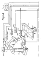
- FIG. 1 is a schematic view and block diagram of one embodiment in accordance with the present invention.
- reference numeral 10 indicates a six-axis articulated robot, and 12 a rotary table rotating in synchronization therewith.
- the robot 10 is constructed such that it may execute rotational movement about each axis a, b, c, d, e and f, as shown by the arrows.
- On the upper portion of the rotating table 12 is mounted a jig 14 for fixing a workpiece 16, such as a window glass of an automobile, on the rotary table 12.
- a hand portion 18 of the robot 10 applies sealant, paints, deburrs, polishes, emplaces rubber elements, and engages in other operations on the workpiece 16.
- the rotary table 12 is constructed for rotational movement about its rotational shaft.
- the amount of rotational movement is controlled by a driving signal delivered from a control circuit 20.
- the rotational position of the rotary table 12 is monitored by an encoder and a potentiometer mounted on its rotational shaft. The detected output is fed back to the control circuit side to control the position.
- the amount of rotation in each axis of the robot 10 is controlled by a driving signal from the control circuit 20.
- the rotational position is also detected by an encoder and a potentiometer for feedback to the control circuit side.
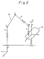
- Figure 2 shows a model pattern of the function of the robot 10 and the rotary table 12 of Fig. 1.
- the a-axis axis of swivel base 10a
- the X-axis and Y-axis are set horizontally and perpendicularly to the Z-axis.
- the rotational shaft of the rotary table 12 is taken as the W-axis and a U-axis and V-axis set horizontally and perpendicularly to the W-axis to form a rotary table coordinate system.
- teaching is executed using this rotary table coordinate system.
- the hand of the robot moves in the U-W plane of the rotary table coordinate system.
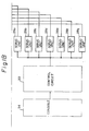
- Figure 3 is a block diagram of an example of the control circuit of Fig. 1.
- reference numerals 29a(1), 29b(1), ..., 29f(1) are servomotors of each axis of the robot 10.
- Reference numeral 29g(1) is a servomotor for the rotational shaft of the rotary table 12.
- encoders 29a(2), 29b(2),... 29f(2), 29g(2) and potentiometers 29a(3), 29b(3), 29f(3) are set to detect the position of rotational movement due to each servomotor.
- Each distinct driving pulse is applied to each servomotor 29a(1), 29b(1), ..., 29f(1), 29g(1) from each servo unit 28a, 28b,..., 28f, 28g.
- each piece of information on the present position detected is sent to each servo unit 28a, 28b, ..., 28f, 28g from each encoder 29(a)2, 29b(2), ..., 29f(2), 29g(2) and each potentiometer 29a(3), 29b(3), ..., 29f(3).
- Each servo unit 28a, 28b, ..., 28f, 28g controls the axis positions in response to each indicated value sent from a central processing unit (CPU) 32 or microcomputer 32 through an input/output (I/O) port 30.
- CPU central processing unit
- I/O input/output
- Each potentiometer 29a(3), 29b(3), ...,29f(3) detects the rough position of rotational movement of each axis, while each encoder 29a(2), 29b(2),..., 29f(2), 29g(2) detects the precise position of rotational movement.
- reference numeral 34 denotes a console to input and/or output the data from the operation side and is composed of a teaching box 34a, a keyboard 34b, and a cathode ray tube (CRT) display 34c.
- CTR cathode ray tube
- Reference numeral 36 denotes a memory which stores the input data, teaching data, and so on from the console 34, 38 an interpolating device for implementing path interpolation as during playback, and 40 a coordinate transformation device for rotating an interpolation point on the rotary table coordinate system and transforming a post-rotation point from the rotary table coordinate system to the absolute coordinate system.
- the teaching operation is performed with the rotary table 12 not rotating but kept fixed at a predetermined position.
- An operator moves the hand portion 18 of the robot 10 to teach the operation, thereby obtaining the position of the tools of the robot 10 and the attitude data of the hand in the absolute coordinate system.
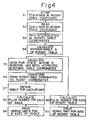
- the playback operation follows the procedure shown in Fig. 4.
- the spacing between two points H0 and H1 in the teaching data on the rotary table coordinate system is interpolated linearly to obtain the path of the hand of the robot 10. This is done by the conventional method of connecting by a straight line the two teaching points H0 and H1 in the teaching data stored in the memory 36 and dividing the line to obtain points P1, P2, P3,..., P i indicating the movement of the hand with a time ⁇ t. As the time ⁇ t, tens of milliseconds are selected.
- the interpolation point P i may be rotated by ⁇ i around the W-axis of the rotary table coordinate system, if the prior interpolation point P i-1 was superposed onto the U-axis.
- Fig. 5 Assuming the projection of the first point P0 of the teaching data on the U-V plane falls on the U-axis, the rotational angle ⁇ 1 from the point P0 to the first interpolation point P1 is obtained from the above-mentioned equation (3). By carrying out a rotation of angle ⁇ 1 with respect to the W-axis from point P1, point P1' is reached.
- the matrix of the point P1' is calculated by the following equation.
- This M r (P1') is transformed to the angle of each axis of the robot 10, matched with the number pulses of the encoders of each axis, the servomotors 29a(1), 29b(1), ..., 29f(1), are driven for movement of the hand of the robot to the interpolation point P1 shown in Fig. 5.
- the number of pulses of the encoder corresponding to ⁇ 1 is calculated and the servomotor 29g(1) is driven whereupon the rotary table 12 rotates by ⁇ 1. Therefore, the hand of the robot 10 and the workpiece 16 of the rotary table 12 meet at the point P1' which is reached by the rotation of an angle ⁇ 1 with respect to the W-axis from point P1.
- the above-described computation is effected for the other interpolation points P2, P3, ... P i in real time.
- Each interpolation point is rotated to a point projected on the U-axis of the rotary table coordinate system every time ⁇ t, and, as a value at said time, transformed to the robot absolute coordinate system.
- the rotary table 12 is rotated to the point projected on the U-axis after ⁇ t seconds, so it can move to the same point with the robot 10.
- the hand of the robot 10 executes only two-dimensional movement on the plane of U-W, as shown in Fig. 2.
- ⁇ t is an extremely short time, such as several tens of msec
- the command values of the interpolation points which are successively output enable the robot 10 and the rotary table 12 to be controlled continuously in perfect synchronization.
- the robot apparatus of the above embodiments stores teaching data as values of the rotary table coordinate system and seeks each interpolation point by linear interpolation on the rotary table coordinate system. Therefore, the interpolation during playback becomes much simple and high precise.
- the robot apparatus of the present invention is designed so that neither the robot nor the rotary table have to move linearly, replacing this with movement of the robot hand on a straight line in a same plane.
- linear interpolation enables a shorter computation time, and there is no necessary to prolong the real-time computation time drastically, the sampling time can be kept to less than several tens of msec. This eliminates the deterioration in precision resulting from prolongation of the sampling time.
Applications Claiming Priority (2)
| Application Number | Priority Date | Filing Date | Title |
|---|---|---|---|
| JP59047179A JPS60193016A (ja) | 1984-03-14 | 1984-03-14 | ロボツト装置 |
| JP47179/84 | 1984-03-14 |
Publications (3)
| Publication Number | Publication Date |
|---|---|
| EP0158447A1 EP0158447A1 (en) | 1985-10-16 |
| EP0158447B1 EP0158447B1 (en) | 1989-07-26 |
| EP0158447B2 true EP0158447B2 (en) | 1994-01-05 |
Family
ID=12767850
Family Applications (1)
| Application Number | Title | Priority Date | Filing Date |
|---|---|---|---|
| EP85301727A Expired - Lifetime EP0158447B2 (en) | 1984-03-14 | 1985-03-13 | System for controlling a robot in association with a rotary table |
Country Status (4)
| Country | Link |
|---|---|
| US (1) | US4836742A (ja) |
| EP (1) | EP0158447B2 (ja) |
| JP (1) | JPS60193016A (ja) |
| DE (1) | DE3571885D1 (ja) |
Families Citing this family (35)
| Publication number | Priority date | Publication date | Assignee | Title |
|---|---|---|---|---|
| JPH0712597B2 (ja) * | 1984-04-27 | 1995-02-15 | 株式会社神戸製鋼所 | 工業用ロボットとポジショナの連動制御システム |
| JPS6142004A (ja) * | 1984-08-06 | 1986-02-28 | Toyota Central Res & Dev Lab Inc | 追従ロボツト装置 |
| JPS6329806A (ja) * | 1986-07-24 | 1988-02-08 | Toyota Motor Corp | 複数の回転テ−ブルを有するロボツト装置の制御方法 |
| JPS6374583A (ja) * | 1986-09-16 | 1988-04-05 | 三菱重工業株式会社 | 作業ロボツト装置 |
| JPS63113605A (ja) * | 1986-10-30 | 1988-05-18 | Toyota Motor Corp | 同期型ロボツト装置の動作制御方法 |
| DE3774090D1 (de) * | 1986-11-17 | 1991-11-28 | Siemens Ag | Verfahren zum steuern der dreidimensionalen relativbewegung eines roboters gegenueber einem an einem werkstuecktraeger befestigten werkstueck. |
| JPS63156679A (ja) * | 1986-12-19 | 1988-06-29 | トキコ株式会社 | 工業用ロボツト |
| JP2652789B2 (ja) * | 1987-12-05 | 1997-09-10 | ファナック 株式会社 | 円弧トラッキング制御方式 |
| JP2787207B2 (ja) * | 1988-05-09 | 1998-08-13 | 株式会社日立製作所 | 多軸位置サーボ装置 |
| JP2652880B2 (ja) * | 1988-08-31 | 1997-09-10 | ファナック株式会社 | 垂直多関節形ロボット |
| US5055755A (en) * | 1989-05-31 | 1991-10-08 | Kabushiki Kaisha Toshiba | Distribution control apparatus |
| JP2694669B2 (ja) * | 1989-06-09 | 1997-12-24 | 株式会社日立製作所 | ロボットの動作制御方法 |
| JP2979552B2 (ja) * | 1989-08-29 | 1999-11-15 | 株式会社安川電機 | ロボットの制御方法 |
| FI83175C (fi) * | 1989-09-12 | 1991-06-10 | Aitec Oy | Foerfarande foer banstyrning av en robotcell. |
| FI83176C (fi) * | 1989-09-12 | 1991-06-10 | Aitec Oy | Foerfarande foer styrning av roerelser hos en robot och en styckemanipulator under en robotcells inlaerningsskede. |
| JPH03196981A (ja) * | 1989-12-25 | 1991-08-28 | Fanuc Ltd | ロボットの付加軸追従制御方式 |
| JPH0830978B2 (ja) * | 1990-05-22 | 1996-03-27 | 株式会社神戸製鋼所 | 産業用ロボットの教示・再生方法 |
| JP2649463B2 (ja) * | 1992-09-29 | 1997-09-03 | 川崎重工業株式会社 | 回転外部軸を有する産業用ロボットの教示方法およびそれに用いる教示装置 |
| US5323174A (en) * | 1992-12-02 | 1994-06-21 | Matthew H. Klapman | Device for determining an orientation of at least a portion of a living body |
| WO1995005270A1 (fr) * | 1993-08-18 | 1995-02-23 | Kabushiki Kaisha Yaskawa Denki | Ensemble poignet pour robots articules |
| JP3476287B2 (ja) * | 1995-08-31 | 2003-12-10 | ファナック株式会社 | ロボットの接続動作時に速度制御を行なうための曲線補間方法 |
| KR20040035357A (ko) * | 2002-10-22 | 2004-04-29 | 삼성전자주식회사 | 다축 로봇의 제어 장치 및 방법 |
| EP1473123B1 (de) * | 2003-04-30 | 2018-06-06 | Günther Battenberg | System zum Erfassen, Beeinflussen und Ausnutzen von Roboterbewegungen |
| ATE401170T1 (de) * | 2004-10-25 | 2008-08-15 | Univ Dayton | Verfahren und system zum ermöglichen von erhöhter genauigkeit bei mehrfachverbundenen robotern durch berechnung der kinematischen robotermodellparameter |
| US7316604B1 (en) * | 2005-12-16 | 2008-01-08 | Global Aero Services, Inc. | Aircraft transparency polisher and/or surface refinisher |
| US8214415B2 (en) | 2008-04-18 | 2012-07-03 | Motion Engineering Incorporated | Interpolator for a networked motion control system |
| DE102009012328A1 (de) * | 2009-03-09 | 2010-09-16 | Weber Maschinenbau Gmbh Breidenbach | Vorrichtung zum Betreiben eines Roboters |
| DE102011084412A1 (de) | 2011-10-13 | 2013-04-18 | Kuka Roboter Gmbh | Robotersteuerungsverfahren |
| DE102015220525B4 (de) | 2015-10-21 | 2023-06-29 | Lufthansa Technik Aktiengesellschaft | Vorrichtung und Verfahren zur Bearbeitung eines Bauteils |
| GB2552019B (en) | 2016-07-08 | 2020-01-08 | Rolls Royce Plc | Methods and apparatus for controlling at least one of a first robot and a second robot to collaborate within a system |
| JP7199073B2 (ja) * | 2017-10-20 | 2023-01-05 | 株式会社キーレックス | 垂直多関節ロボットの教示データ作成システム |
| JP6923429B2 (ja) * | 2017-12-18 | 2021-08-18 | トヨタ自動車株式会社 | ワークに対する作業方法 |
| US10969760B2 (en) | 2018-04-12 | 2021-04-06 | Faro Technologies, Inc. | Coordinate measurement system with auxiliary axis |
| US11874101B2 (en) | 2018-04-12 | 2024-01-16 | Faro Technologies, Inc | Modular servo cartridges for precision metrology |
| CN110561421B (zh) * | 2019-08-09 | 2021-03-19 | 哈尔滨工业大学(深圳) | 机械臂间接拖动示教方法及装置 |
Family Cites Families (27)
| Publication number | Priority date | Publication date | Assignee | Title |
|---|---|---|---|---|
| US3951273A (en) * | 1973-02-02 | 1976-04-20 | Fadal Engineering Company, Inc. | Removable attachment for automating milling machines |
| JPS50112969A (ja) * | 1974-02-18 | 1975-09-04 | ||
| US3920972A (en) * | 1974-07-16 | 1975-11-18 | Cincinnati Milacron Inc | Method and apparatus for programming a computer operated robot arm |
| JPS51113082A (en) * | 1975-03-28 | 1976-10-05 | Shin Meiwa Ind Co Ltd | An automatic control apparatus of a position |
| JPS5561810A (en) * | 1978-11-01 | 1980-05-09 | Shin Meiwa Ind Co Ltd | Position control unit |
| FR2458363A1 (fr) * | 1979-06-13 | 1981-01-02 | Matrasur | Manipulateur d'outil |
| US4420812A (en) * | 1979-09-14 | 1983-12-13 | Tokico, Ltd. | Teaching- playback robot |
| JPS5659306A (en) * | 1979-10-19 | 1981-05-22 | Tokico Ltd | Robot |
| JPS5682192A (en) * | 1979-12-05 | 1981-07-04 | Fujitsu Ltd | Controlling system for robot |
| JPS56123013A (en) * | 1980-02-29 | 1981-09-26 | Mitsubishi Electric Corp | Numerical control device |
| JPS5715688A (en) * | 1980-06-20 | 1982-01-27 | Osaka Transformer Co Ltd | Robot for processing |
| JPS5783390A (en) * | 1980-11-07 | 1982-05-25 | Hitachi Ltd | Indirect instruction method for articulated type robot |
| JPS584382A (ja) * | 1981-06-26 | 1983-01-11 | ファナック株式会社 | 工業用ロボツトの制御方式 |
| JPS5814205A (ja) * | 1981-07-16 | 1983-01-27 | Shin Meiwa Ind Co Ltd | 産業用ロボツト |
| JPS58156367A (ja) * | 1982-03-10 | 1983-09-17 | Mazda Motor Corp | ウインドガラスの接着剤自動塗布装置 |
| DE3151173C2 (de) * | 1981-12-23 | 1983-11-03 | Siemens AG, 1000 Berlin und 8000 München | Verfahren zur Steuerung einer Werkzeugmaschine nach einer vorgegebenen Bahnkurve |
| JPS58120483A (ja) * | 1982-01-11 | 1983-07-18 | 株式会社神戸製鋼所 | ロボツトとポジシヨナの連動制御方法 |
| JPS58146905A (ja) * | 1982-02-26 | 1983-09-01 | Okuma Mach Works Ltd | 数値制御装置 |
| JPS59175987A (ja) * | 1983-03-26 | 1984-10-05 | 株式会社東芝 | 多関節ロボツト装置 |
| US4541062A (en) * | 1983-04-26 | 1985-09-10 | Kabushiki Kaisha Kobe Seiko Sho | Method of interlockingly controlling a robot and positioner |
| CA1216343A (en) * | 1983-05-02 | 1987-01-06 | Tomohiro Murata | Method and apparatus for controlling an operation sequence of a machinery |
| JPS6055414A (ja) * | 1983-09-05 | 1985-03-30 | Mitsubishi Electric Corp | 加工装置 |
| AU3583084A (en) * | 1983-12-10 | 1985-06-13 | Aida Engineering Ltd. | Playback grinding robot |
| JPS6142004A (ja) * | 1984-08-06 | 1986-02-28 | Toyota Central Res & Dev Lab Inc | 追従ロボツト装置 |
| US4598380A (en) * | 1984-08-13 | 1986-07-01 | Cincinnati Milacron Inc. | Method and apparatus for controlling manipulator and workpiece positioner |
| JPS6179508A (ja) * | 1984-09-28 | 1986-04-23 | Komatsu Ltd | 数値制御式斜面加工方法 |
| JPS61140909U (ja) * | 1985-02-21 | 1986-09-01 |
-
1984
- 1984-03-14 JP JP59047179A patent/JPS60193016A/ja active Granted
-
1985
- 1985-03-13 DE DE8585301727T patent/DE3571885D1/de not_active Expired
- 1985-03-13 EP EP85301727A patent/EP0158447B2/en not_active Expired - Lifetime
-
1987
- 1987-06-05 US US07/059,227 patent/US4836742A/en not_active Expired - Lifetime
Also Published As
| Publication number | Publication date |
|---|---|
| DE3571885D1 (en) | 1989-08-31 |
| JPH0527125B2 (ja) | 1993-04-20 |
| US4836742A (en) | 1989-06-06 |
| EP0158447B1 (en) | 1989-07-26 |
| EP0158447A1 (en) | 1985-10-16 |
| JPS60193016A (ja) | 1985-10-01 |
Similar Documents
| Publication | Publication Date | Title |
|---|---|---|
| EP0158447B2 (en) | System for controlling a robot in association with a rotary table | |
| US4945493A (en) | Method and system for correcting a robot path | |
| US4835710A (en) | Method of moving and orienting a tool along a curved path | |
| US5020001A (en) | Robot controller | |
| US4969108A (en) | Vision seam tracking method and apparatus for a manipulator | |
| US4598380A (en) | Method and apparatus for controlling manipulator and workpiece positioner | |
| US4453221A (en) | Manipulator with adaptive velocity controlled path motion | |
| US4659971A (en) | Robot controlling system | |
| CA1275670C (en) | Kinematic parameter identification for robotic manipulators | |
| JPS61281305A (ja) | 多関節ロボツト制御装置 | |
| US5014183A (en) | Method and means for path offsets memorization and recall in a manipulator | |
| KR950000814B1 (ko) | 로보트의 동작지시 방법 및 제어장치 | |
| US4635206A (en) | Method and apparatus for oscillating a tool carried by a manipulator | |
| US4972347A (en) | Method and apparatus for determining the correct tool dimensions for a three dimensional tool mounted on a manipulator | |
| JP3070329B2 (ja) | 産業用ロボットシステム | |
| US5373221A (en) | Method and system for estimating robot tool center point speed | |
| US4706000A (en) | Tool posture control system | |
| EP0188626B1 (en) | System for correcting position of tool | |
| JP2002215211A (ja) | 数値制御装置 | |
| JPS6329282B2 (ja) | ||
| KR0155281B1 (ko) | 다관절 로보트의 직선보간방법 | |
| JP2723570B2 (ja) | 3次元レーザのノズル制御方式 | |
| JPH0724762A (ja) | ロボット制御装置 | |
| JP2604838B2 (ja) | 工業用ロボットの制御方法 | |
| JPH0732281A (ja) | ロボット制御装置 |
Legal Events
| Date | Code | Title | Description |
|---|---|---|---|
| PUAI | Public reference made under article 153(3) epc to a published international application that has entered the european phase |
Free format text: ORIGINAL CODE: 0009012 |
|
| 17P | Request for examination filed |
Effective date: 19850321 |
|
| AK | Designated contracting states |
Designated state(s): DE FR GB |
|
| 17Q | First examination report despatched |
Effective date: 19880217 |
|
| GRAA | (expected) grant |
Free format text: ORIGINAL CODE: 0009210 |
|
| AK | Designated contracting states |
Kind code of ref document: B1 Designated state(s): DE FR GB |
|
| ET | Fr: translation filed | ||
| REF | Corresponds to: |
Ref document number: 3571885 Country of ref document: DE Date of ref document: 19890831 |
|
| PLBI | Opposition filed |
Free format text: ORIGINAL CODE: 0009260 |
|
| 26 | Opposition filed |
Opponent name: SIEMENS AG GR PA 2 ERL S Effective date: 19900425 |
|
| PUAH | Patent maintained in amended form |
Free format text: ORIGINAL CODE: 0009272 |
|
| STAA | Information on the status of an ep patent application or granted ep patent |
Free format text: STATUS: PATENT MAINTAINED AS AMENDED |
|
| 27A | Patent maintained in amended form |
Effective date: 19940105 |
|
| AK | Designated contracting states |
Kind code of ref document: B2 Designated state(s): DE FR GB |
|
| ET3 | Fr: translation filed ** decision concerning opposition | ||
| REG | Reference to a national code |
Ref country code: FR Ref legal event code: D6 |
|
| REG | Reference to a national code |
Ref country code: GB Ref legal event code: IF02 |
|
| PGFP | Annual fee paid to national office [announced via postgrant information from national office to epo] |
Ref country code: FR Payment date: 20020312 Year of fee payment: 18 |
|
| PGFP | Annual fee paid to national office [announced via postgrant information from national office to epo] |
Ref country code: GB Payment date: 20020313 Year of fee payment: 18 |
|
| PGFP | Annual fee paid to national office [announced via postgrant information from national office to epo] |
Ref country code: DE Payment date: 20020327 Year of fee payment: 18 |
|
| PG25 | Lapsed in a contracting state [announced via postgrant information from national office to epo] |
Ref country code: GB Free format text: LAPSE BECAUSE OF NON-PAYMENT OF DUE FEES Effective date: 20030313 |
|
| PG25 | Lapsed in a contracting state [announced via postgrant information from national office to epo] |
Ref country code: DE Free format text: LAPSE BECAUSE OF NON-PAYMENT OF DUE FEES Effective date: 20031001 |
|
| GBPC | Gb: european patent ceased through non-payment of renewal fee |
Effective date: 20030313 |
|
| PG25 | Lapsed in a contracting state [announced via postgrant information from national office to epo] |
Ref country code: FR Free format text: LAPSE BECAUSE OF NON-PAYMENT OF DUE FEES Effective date: 20031127 |
|
| REG | Reference to a national code |
Ref country code: FR Ref legal event code: ST |