EP0158447B2 - System for controlling a robot in association with a rotary table - Google Patents
System for controlling a robot in association with a rotary table Download PDFInfo
- Publication number
- EP0158447B2 EP0158447B2 EP85301727A EP85301727A EP0158447B2 EP 0158447 B2 EP0158447 B2 EP 0158447B2 EP 85301727 A EP85301727 A EP 85301727A EP 85301727 A EP85301727 A EP 85301727A EP 0158447 B2 EP0158447 B2 EP 0158447B2
- Authority
- EP
- European Patent Office
- Prior art keywords
- rotary table
- robot
- coordinate system
- axis
- interpolation
- Prior art date
- Legal status (The legal status is an assumption and is not a legal conclusion. Google has not performed a legal analysis and makes no representation as to the accuracy of the status listed.)
- Expired - Lifetime
Links
Images


Classifications
-
- G—PHYSICS
- G05—CONTROLLING; REGULATING
- G05B—CONTROL OR REGULATING SYSTEMS IN GENERAL; FUNCTIONAL ELEMENTS OF SUCH SYSTEMS; MONITORING OR TESTING ARRANGEMENTS FOR SUCH SYSTEMS OR ELEMENTS
- G05B19/00—Program-control systems
- G05B19/02—Program-control systems electric
- G05B19/42—Recording and playback systems, i.e. in which the program is recorded from a cycle of operations, e.g. the cycle of operations being manually controlled, after which this record is played back on the same machine
- G05B19/423—Teaching successive positions by walk-through, i.e. the tool head or end effector being grasped and guided directly, with or without servo-assistance, to follow a path
-
- G—PHYSICS
- G05—CONTROLLING; REGULATING
- G05B—CONTROL OR REGULATING SYSTEMS IN GENERAL; FUNCTIONAL ELEMENTS OF SUCH SYSTEMS; MONITORING OR TESTING ARRANGEMENTS FOR SUCH SYSTEMS OR ELEMENTS
- G05B19/00—Program-control systems
- G05B19/02—Program-control systems electric
- G05B19/418—Total factory control, i.e. centrally controlling a plurality of machines, e.g. direct or distributed numerical control [DNC], flexible manufacturing systems [FMS], integrated manufacturing systems [IMS] or computer integrated manufacturing [CIM]
- G05B19/41815—Total factory control, i.e. centrally controlling a plurality of machines, e.g. direct or distributed numerical control [DNC], flexible manufacturing systems [FMS], integrated manufacturing systems [IMS] or computer integrated manufacturing [CIM] characterised by the cooperation between machine tools, manipulators and conveyor or other workpiece supply system, workcell
- G05B19/4182—Total factory control, i.e. centrally controlling a plurality of machines, e.g. direct or distributed numerical control [DNC], flexible manufacturing systems [FMS], integrated manufacturing systems [IMS] or computer integrated manufacturing [CIM] characterised by the cooperation between machine tools, manipulators and conveyor or other workpiece supply system, workcell manipulators and conveyor only
-
- Y—GENERAL TAGGING OF NEW TECHNOLOGICAL DEVELOPMENTS; GENERAL TAGGING OF CROSS-SECTIONAL TECHNOLOGIES SPANNING OVER SEVERAL SECTIONS OF THE IPC; TECHNICAL SUBJECTS COVERED BY FORMER USPC CROSS-REFERENCE ART COLLECTIONS [XRACs] AND DIGESTS
- Y02—TECHNOLOGIES OR APPLICATIONS FOR MITIGATION OR ADAPTATION AGAINST CLIMATE CHANGE
- Y02P—CLIMATE CHANGE MITIGATION TECHNOLOGIES IN THE PRODUCTION OR PROCESSING OF GOODS
- Y02P90/00—Enabling technologies with a potential contribution to greenhouse gas [GHG] emissions mitigation
- Y02P90/02—Total factory control, e.g. smart factories, flexible manufacturing systems [FMS] or integrated manufacturing systems [IMS]
Definitions
- the present invention relates to a system for controlling an industrial robot in association with a rotary table.
- teaching data is stored in the form of values on a specific coordinate system (absolute coordinate system) of the robot or in the form of displacement (angle) on each axis of the robot.
- this teaching data is used for playback, the interpolative calculations carried out in consideration of the relative movement between the robot and rotary table becomes much more complicated and the overall computation time becomes longer. It is not possible to reduce the interpolation time, so there is a problem of reduced precision of the path.
- the data representing the shape of each workpiece varies with the position of the workpiece with teaching data of the absolute coordinate system.
- teaching data becomes inaccurate and must be revised.
- the present invention intends to solve the above-mentioned problems in the prior art.
- control circuit further carries out a step of adapting the interpolation points calculated by said calculating step to compute the rotational angle of said rotary table; a step of computing the coordinates rotated by said rotational angle around the axis of said rotary table coordinate system, a step of transforming the rotary table coordinate system of the data obtained by said computing step to the robot coordinate system; and a step of operating said robot by the output of the transformation step.
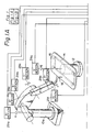
- FIG. 1 is a schematic view and block diagram of one embodiment in accordance with the present invention.
- reference numeral 10 indicates a six-axis articulated robot, and 12 a rotary table rotating in synchronization therewith.
- the robot 10 is constructed such that it may execute rotational movement about each axis a, b, c, d, e and f, as shown by the arrows.
- On the upper portion of the rotating table 12 is mounted a jig 14 for fixing a workpiece 16, such as a window glass of an automobile, on the rotary table 12.
- a hand portion 18 of the robot 10 applies sealant, paints, deburrs, polishes, emplaces rubber elements, and engages in other operations on the workpiece 16.
- the rotary table 12 is constructed for rotational movement about its rotational shaft.
- the amount of rotational movement is controlled by a driving signal delivered from a control circuit 20.
- the rotational position of the rotary table 12 is monitored by an encoder and a potentiometer mounted on its rotational shaft. The detected output is fed back to the control circuit side to control the position.
- the amount of rotation in each axis of the robot 10 is controlled by a driving signal from the control circuit 20.
- the rotational position is also detected by an encoder and a potentiometer for feedback to the control circuit side.
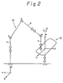
- Figure 2 shows a model pattern of the function of the robot 10 and the rotary table 12 of Fig. 1.
- the a-axis axis of swivel base 10a
- the X-axis and Y-axis are set horizontally and perpendicularly to the Z-axis.
- the rotational shaft of the rotary table 12 is taken as the W-axis and a U-axis and V-axis set horizontally and perpendicularly to the W-axis to form a rotary table coordinate system.
- teaching is executed using this rotary table coordinate system.
- the hand of the robot moves in the U-W plane of the rotary table coordinate system.
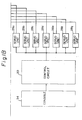
- Figure 3 is a block diagram of an example of the control circuit of Fig. 1.
- reference numerals 29a(1), 29b(1), ..., 29f(1) are servomotors of each axis of the robot 10.
- Reference numeral 29g(1) is a servomotor for the rotational shaft of the rotary table 12.
- encoders 29a(2), 29b(2),... 29f(2), 29g(2) and potentiometers 29a(3), 29b(3), 29f(3) are set to detect the position of rotational movement due to each servomotor.
- Each distinct driving pulse is applied to each servomotor 29a(1), 29b(1), ..., 29f(1), 29g(1) from each servo unit 28a, 28b,..., 28f, 28g.
- each piece of information on the present position detected is sent to each servo unit 28a, 28b, ..., 28f, 28g from each encoder 29(a)2, 29b(2), ..., 29f(2), 29g(2) and each potentiometer 29a(3), 29b(3), ..., 29f(3).
- Each servo unit 28a, 28b, ..., 28f, 28g controls the axis positions in response to each indicated value sent from a central processing unit (CPU) 32 or microcomputer 32 through an input/output (I/O) port 30.
- CPU central processing unit
- I/O input/output
- Each potentiometer 29a(3), 29b(3), ...,29f(3) detects the rough position of rotational movement of each axis, while each encoder 29a(2), 29b(2),..., 29f(2), 29g(2) detects the precise position of rotational movement.
- reference numeral 34 denotes a console to input and/or output the data from the operation side and is composed of a teaching box 34a, a keyboard 34b, and a cathode ray tube (CRT) display 34c.
- CTR cathode ray tube
- Reference numeral 36 denotes a memory which stores the input data, teaching data, and so on from the console 34, 38 an interpolating device for implementing path interpolation as during playback, and 40 a coordinate transformation device for rotating an interpolation point on the rotary table coordinate system and transforming a post-rotation point from the rotary table coordinate system to the absolute coordinate system.
- the teaching operation is performed with the rotary table 12 not rotating but kept fixed at a predetermined position.
- An operator moves the hand portion 18 of the robot 10 to teach the operation, thereby obtaining the position of the tools of the robot 10 and the attitude data of the hand in the absolute coordinate system.
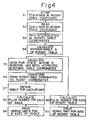
- the playback operation follows the procedure shown in Fig. 4.
- the spacing between two points H0 and H1 in the teaching data on the rotary table coordinate system is interpolated linearly to obtain the path of the hand of the robot 10. This is done by the conventional method of connecting by a straight line the two teaching points H0 and H1 in the teaching data stored in the memory 36 and dividing the line to obtain points P1, P2, P3,..., P i indicating the movement of the hand with a time ⁇ t. As the time ⁇ t, tens of milliseconds are selected.
- the interpolation point P i may be rotated by ⁇ i around the W-axis of the rotary table coordinate system, if the prior interpolation point P i-1 was superposed onto the U-axis.
- Fig. 5 Assuming the projection of the first point P0 of the teaching data on the U-V plane falls on the U-axis, the rotational angle ⁇ 1 from the point P0 to the first interpolation point P1 is obtained from the above-mentioned equation (3). By carrying out a rotation of angle ⁇ 1 with respect to the W-axis from point P1, point P1' is reached.
- the matrix of the point P1' is calculated by the following equation.
- This M r (P1') is transformed to the angle of each axis of the robot 10, matched with the number pulses of the encoders of each axis, the servomotors 29a(1), 29b(1), ..., 29f(1), are driven for movement of the hand of the robot to the interpolation point P1 shown in Fig. 5.
- the number of pulses of the encoder corresponding to ⁇ 1 is calculated and the servomotor 29g(1) is driven whereupon the rotary table 12 rotates by ⁇ 1. Therefore, the hand of the robot 10 and the workpiece 16 of the rotary table 12 meet at the point P1' which is reached by the rotation of an angle ⁇ 1 with respect to the W-axis from point P1.
- the above-described computation is effected for the other interpolation points P2, P3, ... P i in real time.
- Each interpolation point is rotated to a point projected on the U-axis of the rotary table coordinate system every time ⁇ t, and, as a value at said time, transformed to the robot absolute coordinate system.
- the rotary table 12 is rotated to the point projected on the U-axis after ⁇ t seconds, so it can move to the same point with the robot 10.
- the hand of the robot 10 executes only two-dimensional movement on the plane of U-W, as shown in Fig. 2.
- ⁇ t is an extremely short time, such as several tens of msec
- the command values of the interpolation points which are successively output enable the robot 10 and the rotary table 12 to be controlled continuously in perfect synchronization.
- the robot apparatus of the above embodiments stores teaching data as values of the rotary table coordinate system and seeks each interpolation point by linear interpolation on the rotary table coordinate system. Therefore, the interpolation during playback becomes much simple and high precise.
- the robot apparatus of the present invention is designed so that neither the robot nor the rotary table have to move linearly, replacing this with movement of the robot hand on a straight line in a same plane.
- linear interpolation enables a shorter computation time, and there is no necessary to prolong the real-time computation time drastically, the sampling time can be kept to less than several tens of msec. This eliminates the deterioration in precision resulting from prolongation of the sampling time.
Landscapes
- Engineering & Computer Science (AREA)
- Physics & Mathematics (AREA)
- General Physics & Mathematics (AREA)
- Automation & Control Theory (AREA)
- Robotics (AREA)
- General Engineering & Computer Science (AREA)
- Manufacturing & Machinery (AREA)
- Quality & Reliability (AREA)
- Numerical Control (AREA)
- Manipulator (AREA)
Description
- The present invention relates to a system for controlling an industrial robot in association with a rotary table.
- In the prior art, there is already known an industrial robot which is operated in association with a rotary table mounted with a workpiece. This simplifies the movement on the robot side, speeds up the work, and enables greater compactness. Sometimes, transfer means is annexed to either the robot or rotary table.
- In such a conventional robot apparatus, the robot or rotary table itself is mounted on the transfer shaft of the travelling means. That is to say, a very heavy article is moved. As a result, the transfer shaft and travelling means become large in scale and it is difficult to ensure precision. Further, a large space is necessary for the operation of the travelling means along the transfer shaft. Still further, there are limitations on the disposition of the transfer shaft and the need for adjustment of the positional relation with peripheral equipment.
- In another prior art robot apparatus, teaching data is stored in the form of values on a specific coordinate system (absolute coordinate system) of the robot or in the form of displacement (angle) on each axis of the robot. When this teaching data is used for playback, the interpolative calculations carried out in consideration of the relative movement between the robot and rotary table becomes much more complicated and the overall computation time becomes longer. It is not possible to reduce the interpolation time, so there is a problem of reduced precision of the path. Moreover, there is the disadvantage that the data representing the shape of each workpiece varies with the position of the workpiece with teaching data of the absolute coordinate system. There is a further disadvantage that, when the relative position between the rotary table and the robot is changed due to a change in the position of installation of the robot or the rotary table, the teaching data becomes inaccurate and must be revised.
- The present invention intends to solve the above-mentioned problems in the prior art.
- It is an object of the invention to provide a system for controlling a robot in association with a rotary table wherein the operation time can be shortened and control may be carried out with a high precision.
- In accordance with the present invention, there is provided a system for controlling a robot operating in association with a rotary table as claimed in
claim 1. - Preferably, the control circuit further carries out a step of adapting the interpolation points calculated by said calculating step to compute the rotational angle of said rotary table; a step of computing the coordinates rotated by said rotational angle around the axis of said rotary table coordinate system, a step of transforming the rotary table coordinate system of the data obtained by said computing step to the robot coordinate system; and a step of operating said robot by the output of the transformation step.
- In the drawings:-
- Figure 1 is a schematic view and block diagram of an embodiment of the present invention;
- Fig. 2 is a view of a model pattern of relative movement of the robot and rotary table in Fig. 1;
- Fig. 3 is a block diagram of the control circuit in Fig. 1;
- Fig. 4 is a flow chart of the operation process; and
- Fig. 5 is an explanatory diagram of the interpolation and coordinate transformation.
- In order that the invention and its various preferred features may be understood more easily, embodiments thereof will now be described in detail with reference to the drawings.
- Figure 1 is a schematic view and block diagram of one embodiment in accordance with the present invention. In the figure,
reference numeral 10 indicates a six-axis articulated robot, and 12 a rotary table rotating in synchronization therewith. Therobot 10 is constructed such that it may execute rotational movement about each axis a, b, c, d, e and f, as shown by the arrows. On the upper portion of the rotating table 12 is mounted ajig 14 for fixing aworkpiece 16, such as a window glass of an automobile, on the rotary table 12. Ahand portion 18 of therobot 10 applies sealant, paints, deburrs, polishes, emplaces rubber elements, and engages in other operations on theworkpiece 16. - The rotary table 12 is constructed for rotational movement about its rotational shaft. The amount of rotational movement is controlled by a driving signal delivered from a
control circuit 20. The rotational position of the rotary table 12 is monitored by an encoder and a potentiometer mounted on its rotational shaft. The detected output is fed back to the control circuit side to control the position. On the other hand, the amount of rotation in each axis of therobot 10 is controlled by a driving signal from thecontrol circuit 20. The rotational position is also detected by an encoder and a potentiometer for feedback to the control circuit side. - Figure 2 shows a model pattern of the function of the
robot 10 and the rotary table 12 of Fig. 1. For the absolute coordinate system of therobot 10, the a-axis (axis ofswivel base 10a) is taken as the Z-axis. The X-axis and Y-axis are set horizontally and perpendicularly to the Z-axis. On the other hand, the rotational shaft of the rotary table 12 is taken as the W-axis and a U-axis and V-axis set horizontally and perpendicularly to the W-axis to form a rotary table coordinate system. In accordance with the present invention, teaching is executed using this rotary table coordinate system. - The hand of the robot moves in the U-W plane of the rotary table coordinate system.
- Figure 3 is a block diagram of an example of the control circuit of Fig. 1. In the figure,
reference numerals 29a(1), 29b(1), ..., 29f(1) are servomotors of each axis of therobot 10.Reference numeral 29g(1) is a servomotor for the rotational shaft of the rotary table 12. On each axis,encoders 29a(2), 29b(2),... 29f(2), 29g(2) andpotentiometers 29a(3), 29b(3), 29f(3), are set to detect the position of rotational movement due to each servomotor. Each distinct driving pulse is applied to eachservomotor 29a(1), 29b(1), ..., 29f(1), 29g(1) from eachservo unit servo unit potentiometer 29a(3), 29b(3), ..., 29f(3). Eachservo unit microcomputer 32 through an input/output (I/O)port 30. - Each
potentiometer 29a(3), 29b(3), ...,29f(3) detects the rough position of rotational movement of each axis, while eachencoder 29a(2), 29b(2),..., 29f(2), 29g(2) detects the precise position of rotational movement. As shown in Fig. 3,reference numeral 34 denotes a console to input and/or output the data from the operation side and is composed of ateaching box 34a, akeyboard 34b, and a cathode ray tube (CRT)display 34c.Reference numeral 36 denotes a memory which stores the input data, teaching data, and so on from theconsole - The operation of the system will now be explained with reference to Fig. 1.
- The teaching operation is performed with the rotary table 12 not rotating but kept fixed at a predetermined position. An operator moves the
hand portion 18 of therobot 10 to teach the operation, thereby obtaining the position of the tools of therobot 10 and the attitude data of the hand in the absolute coordinate system. - Using the robot coordinate system X, Y, and Z and the rotary table coordinate system U, V, and W and representing both coordinate systems as a matrix Mr(H), the following equation can be obtained.

where X, Y, and Z denote the positional data of the hand; N(X), N(Y), and N(Z) normal vector; O(X), O(Y), and O(Z) orientation vector; and A(X), A(Y), and A(Z) approach vector. - As shown in Fig. 1 and Fig. 2, when the transformation matrix from the rotary table coordinate system (U, V, W) to the robot absolute coordinate system (X, Y, Z) is taken as T and the inverse matrix of the above-mentioned transformation matrix is taken as T⁻¹, the position and attitude data Mt(H) in the rotary table coordinate system is represented by the following equation (2). The position and attitude data of the robot absolute coordinate system obtained by the teaching data is transformed to the position and attitude data of this rotary table coordinate system and then stored in a
memory 36 as the teaching data. Therefore, when a matrix of the robot coordinate system is represented as Mr(H) and a matrix of the rotary table coordinate system as Mt(H), then
- The playback operation follows the procedure shown in Fig. 4. First, the spacing between two points H₀ and H₁ in the teaching data on the rotary table coordinate system is interpolated linearly to obtain the path of the hand of the
robot 10. This is done by the conventional method of connecting by a straight line the two teaching points H₀ and H₁ in the teaching data stored in thememory 36 and dividing the line to obtain points P₁, P₂, P₃,..., Pi indicating the movement of the hand with a time Δt. As the time Δt, tens of milliseconds are selected. - The rotational angle component on the rotary table coordinate system of each interpolation point P₁, P₂, ... Pi thus obtained is obtained next. If the rotational angle component of the rotary table coordinate system of the interpolation point Pi is taken as ϑi, then

where PiU is a U-component of the interpolation point Pi on the rotary table coordinate system and PiV is a V-component of the interpolation point Pi on the rotary table coordinate system. - To superpose the interpolation point Pi onto the U-axis when tis interpolation point Pi is projected on the U-V plane of the rotary table coordinate system, the interpolation point Pi may be rotated by ϑi around the W-axis of the rotary table coordinate system, if the prior interpolation point Pi-1 was superposed onto the U-axis. This will be explained more concretely using Fig. 5. Assuming the projection of the first point P₀ of the teaching data on the U-V plane falls on the U-axis, the rotational angle ϑ₁ from the point P₀ to the first interpolation point P₁ is obtained from the above-mentioned equation (3). By carrying out a rotation of angle ϑ₁ with respect to the W-axis from point P₁, point P₁' is reached. The matrix of the point P₁' is calculated by the following equation.

- Using the above-described transformation matrix T, the post-rotation point P₁' is transformed to values of the absolute coordinate system of the
robot 10. Taking the interpolation point on the robot absolute coordinate system as Mr(P₁'), the following equation is obtained.
- This Mr(P₁') is transformed to the angle of each axis of the
robot 10, matched with the number pulses of the encoders of each axis, theservomotors 29a(1), 29b(1), ..., 29f(1), are driven for movement of the hand of the robot to the interpolation point P₁ shown in Fig. 5. - On the other hand, as for the rotary table 12, the number of pulses of the encoder corresponding to ϑ₁ is calculated and the
servomotor 29g(1) is driven whereupon the rotary table 12 rotates by ϑ₁. Therefore, the hand of therobot 10 and theworkpiece 16 of the rotary table 12 meet at the point P₁' which is reached by the rotation of an angle ϑ₁ with respect to the W-axis from point P₁. In the same way, the above-described computation is effected for the other interpolation points P₂, P₃, ... Pi in real time. Each interpolation point is rotated to a point projected on the U-axis of the rotary table coordinate system every time Δt, and, as a value at said time, transformed to the robot absolute coordinate system. The rotary table 12 is rotated to the point projected on the U-axis after Δt seconds, so it can move to the same point with therobot 10. - As is apparent from the above-described explanation, the hand of the
robot 10 executes only two-dimensional movement on the plane of U-W, as shown in Fig. 2. As Δt is an extremely short time, such as several tens of msec, the command values of the interpolation points, which are successively output enable therobot 10 and the rotary table 12 to be controlled continuously in perfect synchronization. - As described above, the robot apparatus of the above embodiments stores teaching data as values of the rotary table coordinate system and seeks each interpolation point by linear interpolation on the rotary table coordinate system. Therefore, the interpolation during playback becomes much simple and high precise.
- As the robot apparatus of the present invention uses linear interpolation for path interpolation, computations are easier in comparison with circular arc interpolation and the like. As the path between two points is linear, an operator can easily infer how the hand of the robot moves on a same plane during playback. Consequently, teaching becomes simple and the safety of the apparatus as a whole can be more easily ensured.
- The robot apparatus of the present invention is designed so that neither the robot nor the rotary table have to move linearly, replacing this with movement of the robot hand on a straight line in a same plane. Thus, the conventional problems of the larger size of the apparatus resulting from the provision of travelling means for linear movement of the robot or rotary table, the difficulty of maintenance of precision, and the need for a large space and adjustment of the relative position of peripheral equipment are eliminated.
- Further, as the interpolation points are calculated in real time during playback, only 1/15th of the data in the case of computing the interpolation points in advance need be stored in the
memory 36. - Furthermore, linear interpolation enables a shorter computation time, and there is no necessary to prolong the real-time computation time drastically, the sampling time can be kept to less than several tens of msec. This eliminates the deterioration in precision resulting from prolongation of the sampling time.
- Still further, as the robot hand is moved only in two dimensions, as shown by U and W in the figures, it is much easier to supply slender, continuous members in attaching such members around the workpiece.
- It should be noted that while the above-described embodiment was explained in reference to linear interpolation used for the path interpolation, curve interpolation or a combination of linear and curve interpolation may also be adopted depending upon the particular purpose.
Claims (2)
- A system for controlling a robot operating in association with a rotary table, comprising:
a multi-joint robot adapted to carry out an operation of three-dimensional positions and attitudes in a robot Cartesian coordinate system;
a rotary table adapted to rotate in synchronization with the operation of said robot and having a supporting plane to carry a workpiece; and
a control circuit for interpolating teaching data on the workpiece and generating, on the basis of said interpolated teaching data, a signal for defining the operation of the robot in said Cartesian coordinate system and a signal representing a rotational angle for defining the operation of said rotary table;
said control circuit carrying out a step of composing and storing teaching data as values on a rotary table coordinate system, the axis (W) about which the rotary table rotates being perpendicular to said workpiece supporting plane of the rotary table, so that it is vertical when said workpiece supporting plane is disposed horizontally and a step of calculating each of the interpolation points by carrying out path interpolation of said stored teaching data on the rotary table coordinate system. - A system according to claim 1, wherein said control circuit further carries out a step of calculating the rotational angle of the rotary table which is required to be rotated, a step of computing the coordinates rotated by said rotational angle around the axis of rotation of said rotary table, a step of transforming the data obtained by said computing step from the rotary table coordinates to the robot coordinates, and a step of operating said robot by the output of the transformation step.
Applications Claiming Priority (2)
| Application Number | Priority Date | Filing Date | Title |
|---|---|---|---|
| JP59047179A JPS60193016A (en) | 1984-03-14 | 1984-03-14 | Robot device |
| JP47179/84 | 1984-03-14 |
Publications (3)
| Publication Number | Publication Date |
|---|---|
| EP0158447A1 EP0158447A1 (en) | 1985-10-16 |
| EP0158447B1 EP0158447B1 (en) | 1989-07-26 |
| EP0158447B2 true EP0158447B2 (en) | 1994-01-05 |
Family
ID=12767850
Family Applications (1)
| Application Number | Title | Priority Date | Filing Date |
|---|---|---|---|
| EP85301727A Expired - Lifetime EP0158447B2 (en) | 1984-03-14 | 1985-03-13 | System for controlling a robot in association with a rotary table |
Country Status (4)
| Country | Link |
|---|---|
| US (1) | US4836742A (en) |
| EP (1) | EP0158447B2 (en) |
| JP (1) | JPS60193016A (en) |
| DE (1) | DE3571885D1 (en) |
Families Citing this family (35)
| Publication number | Priority date | Publication date | Assignee | Title |
|---|---|---|---|---|
| JPH0712597B2 (en) * | 1984-04-27 | 1995-02-15 | 株式会社神戸製鋼所 | Interlocking control system for industrial robot and positioner |
| JPS6142004A (en) * | 1984-08-06 | 1986-02-28 | Toyota Central Res & Dev Lab Inc | Following-up robot device |
| JPS6329806A (en) * | 1986-07-24 | 1988-02-08 | Toyota Motor Corp | Method for controlling robot device having plural rotary table |
| JPS6374583A (en) * | 1986-09-16 | 1988-04-05 | 三菱重工業株式会社 | Working robot device |
| JPS63113605A (en) * | 1986-10-30 | 1988-05-18 | Toyota Motor Corp | Operation control method for synchronous robot device |
| DE3774090D1 (en) * | 1986-11-17 | 1991-11-28 | Siemens Ag | METHOD FOR CONTROLLING THE THREE-DIMENSIONAL RELATIVE MOVEMENT OF A ROBOT AGAINST A WORKPIECE ATTACHED TO A WORKPIECE CARRIER. |
| JPS63156679A (en) * | 1986-12-19 | 1988-06-29 | トキコ株式会社 | industrial robot |
| JP2652789B2 (en) * | 1987-12-05 | 1997-09-10 | ファナック 株式会社 | Arc tracking control method |
| JP2787207B2 (en) * | 1988-05-09 | 1998-08-13 | 株式会社日立製作所 | Multi-axis position servo device |
| JP2652880B2 (en) * | 1988-08-31 | 1997-09-10 | ファナック株式会社 | Vertical articulated robot |
| US5055755A (en) * | 1989-05-31 | 1991-10-08 | Kabushiki Kaisha Toshiba | Distribution control apparatus |
| JP2694669B2 (en) * | 1989-06-09 | 1997-12-24 | 株式会社日立製作所 | Robot motion control method |
| JP2979552B2 (en) * | 1989-08-29 | 1999-11-15 | 株式会社安川電機 | Robot control method |
| FI83175C (en) * | 1989-09-12 | 1991-06-10 | Aitec Oy | Procedure for path control of a robotic cell |
| FI83176C (en) * | 1989-09-12 | 1991-06-10 | Aitec Oy | A method for controlling the movements of a robot and a piece manipulator during the learning phase of a robot cell |
| JPH03196981A (en) * | 1989-12-25 | 1991-08-28 | Fanuc Ltd | Additive shaft follow-up control system for robot |
| JPH0830978B2 (en) * | 1990-05-22 | 1996-03-27 | 株式会社神戸製鋼所 | Teaching / reproducing method for industrial robots |
| JP2649463B2 (en) * | 1992-09-29 | 1997-09-03 | 川崎重工業株式会社 | Method of teaching an industrial robot having a rotating external axis and teaching device used therefor |
| US5323174A (en) * | 1992-12-02 | 1994-06-21 | Matthew H. Klapman | Device for determining an orientation of at least a portion of a living body |
| WO1995005270A1 (en) * | 1993-08-18 | 1995-02-23 | Kabushiki Kaisha Yaskawa Denki | Wrist structure for articulated robots |
| JP3476287B2 (en) * | 1995-08-31 | 2003-12-10 | ファナック株式会社 | Curve interpolation method for speed control during robot connection operation |
| KR20040035357A (en) * | 2002-10-22 | 2004-04-29 | 삼성전자주식회사 | Control apparatus and method for multi-axis robot |
| EP1473123B1 (en) * | 2003-04-30 | 2018-06-06 | Günther Battenberg | System for detecting, modifying and exploiting the movements of a robot |
| WO2006086021A2 (en) * | 2004-10-25 | 2006-08-17 | University Of Dayton | Method and system to provide improved accuracies in multi-jointed robots through kinematic robot model parameters determination |
| US7316604B1 (en) * | 2005-12-16 | 2008-01-08 | Global Aero Services, Inc. | Aircraft transparency polisher and/or surface refinisher |
| US8214415B2 (en) | 2008-04-18 | 2012-07-03 | Motion Engineering Incorporated | Interpolator for a networked motion control system |
| DE102009012328A1 (en) * | 2009-03-09 | 2010-09-16 | Weber Maschinenbau Gmbh Breidenbach | Device for operating a robot |
| DE102011084412A1 (en) | 2011-10-13 | 2013-04-18 | Kuka Roboter Gmbh | Robot control method |
| DE102015220525B4 (en) | 2015-10-21 | 2023-06-29 | Lufthansa Technik Aktiengesellschaft | Device and method for processing a component |
| GB2552019B (en) | 2016-07-08 | 2020-01-08 | Rolls Royce Plc | Methods and apparatus for controlling at least one of a first robot and a second robot to collaborate within a system |
| JP7199073B2 (en) * | 2017-10-20 | 2023-01-05 | 株式会社キーレックス | Teaching data creation system for vertical articulated robots |
| JP6923429B2 (en) * | 2017-12-18 | 2021-08-18 | トヨタ自動車株式会社 | Work method for work |
| US10969760B2 (en) * | 2018-04-12 | 2021-04-06 | Faro Technologies, Inc. | Coordinate measurement system with auxiliary axis |
| US11874101B2 (en) | 2018-04-12 | 2024-01-16 | Faro Technologies, Inc | Modular servo cartridges for precision metrology |
| CN110561421B (en) * | 2019-08-09 | 2021-03-19 | 哈尔滨工业大学(深圳) | Mechanical arm indirect dragging demonstration method and device |
Family Cites Families (27)
| Publication number | Priority date | Publication date | Assignee | Title |
|---|---|---|---|---|
| US3951273A (en) * | 1973-02-02 | 1976-04-20 | Fadal Engineering Company, Inc. | Removable attachment for automating milling machines |
| JPS50112969A (en) * | 1974-02-18 | 1975-09-04 | ||
| US3920972A (en) * | 1974-07-16 | 1975-11-18 | Cincinnati Milacron Inc | Method and apparatus for programming a computer operated robot arm |
| JPS51113082A (en) * | 1975-03-28 | 1976-10-05 | Shin Meiwa Ind Co Ltd | An automatic control apparatus of a position |
| JPS5561810A (en) * | 1978-11-01 | 1980-05-09 | Shin Meiwa Ind Co Ltd | Position control unit |
| FR2458363A1 (en) * | 1979-06-13 | 1981-01-02 | Matrasur | Mechanism for manipulating spray gun for revolving workpiece - uses radial axle to mount support on slide traversing swivel mast |
| US4420812A (en) * | 1979-09-14 | 1983-12-13 | Tokico, Ltd. | Teaching- playback robot |
| JPS5659306A (en) * | 1979-10-19 | 1981-05-22 | Tokico Ltd | Robot |
| JPS5682192A (en) * | 1979-12-05 | 1981-07-04 | Fujitsu Ltd | Controlling system for robot |
| JPS56123013A (en) * | 1980-02-29 | 1981-09-26 | Mitsubishi Electric Corp | Numerical control device |
| JPS5715688A (en) * | 1980-06-20 | 1982-01-27 | Osaka Transformer Co Ltd | Robot for processing |
| JPS5783390A (en) * | 1980-11-07 | 1982-05-25 | Hitachi Ltd | Indirect instruction method for articulated type robot |
| JPS584382A (en) * | 1981-06-26 | 1983-01-11 | ファナック株式会社 | Control system for industrial robot |
| JPS5814205A (en) * | 1981-07-16 | 1983-01-27 | Shin Meiwa Ind Co Ltd | industrial robot |
| JPS58156367A (en) * | 1982-03-10 | 1983-09-17 | Mazda Motor Corp | Apparatus for automatically applying adhesive agent to window glass |
| DE3151173C2 (en) * | 1981-12-23 | 1983-11-03 | Siemens AG, 1000 Berlin und 8000 München | Method for controlling a machine tool according to a specified trajectory |
| JPS58120483A (en) * | 1982-01-11 | 1983-07-18 | 株式会社神戸製鋼所 | Cooperational control of robot and positioner |
| JPS58146905A (en) * | 1982-02-26 | 1983-09-01 | Okuma Mach Works Ltd | Controlling device of numeral |
| JPS59175987A (en) * | 1983-03-26 | 1984-10-05 | 株式会社東芝 | Multi-joint robot device |
| US4541062A (en) * | 1983-04-26 | 1985-09-10 | Kabushiki Kaisha Kobe Seiko Sho | Method of interlockingly controlling a robot and positioner |
| CA1216343A (en) * | 1983-05-02 | 1987-01-06 | Tomohiro Murata | Method and apparatus for controlling an operation sequence of a machinery |
| JPS6055414A (en) * | 1983-09-05 | 1985-03-30 | Mitsubishi Electric Corp | processing equipment |
| AU3583084A (en) * | 1983-12-10 | 1985-06-13 | Aida Engineering Ltd. | Playback grinding robot |
| JPS6142004A (en) * | 1984-08-06 | 1986-02-28 | Toyota Central Res & Dev Lab Inc | Following-up robot device |
| US4598380A (en) * | 1984-08-13 | 1986-07-01 | Cincinnati Milacron Inc. | Method and apparatus for controlling manipulator and workpiece positioner |
| JPS6179508A (en) * | 1984-09-28 | 1986-04-23 | Komatsu Ltd | Numerical control slope machining method |
| JPS61140909U (en) * | 1985-02-21 | 1986-09-01 |
-
1984
- 1984-03-14 JP JP59047179A patent/JPS60193016A/en active Granted
-
1985
- 1985-03-13 DE DE8585301727T patent/DE3571885D1/en not_active Expired
- 1985-03-13 EP EP85301727A patent/EP0158447B2/en not_active Expired - Lifetime
-
1987
- 1987-06-05 US US07/059,227 patent/US4836742A/en not_active Expired - Lifetime
Also Published As
| Publication number | Publication date |
|---|---|
| JPH0527125B2 (en) | 1993-04-20 |
| EP0158447A1 (en) | 1985-10-16 |
| US4836742A (en) | 1989-06-06 |
| JPS60193016A (en) | 1985-10-01 |
| EP0158447B1 (en) | 1989-07-26 |
| DE3571885D1 (en) | 1989-08-31 |
Similar Documents
| Publication | Publication Date | Title |
|---|---|---|
| EP0158447B2 (en) | System for controlling a robot in association with a rotary table | |
| US4945493A (en) | Method and system for correcting a robot path | |
| US4835710A (en) | Method of moving and orienting a tool along a curved path | |
| US5020001A (en) | Robot controller | |
| US4969108A (en) | Vision seam tracking method and apparatus for a manipulator | |
| US4598380A (en) | Method and apparatus for controlling manipulator and workpiece positioner | |
| US4453221A (en) | Manipulator with adaptive velocity controlled path motion | |
| US4659971A (en) | Robot controlling system | |
| CA1275670C (en) | Kinematic parameter identification for robotic manipulators | |
| US5014183A (en) | Method and means for path offsets memorization and recall in a manipulator | |
| KR950000814B1 (en) | Position teaching method and control apparatus for robot | |
| US4853603A (en) | Control of an industrial robot | |
| US4635206A (en) | Method and apparatus for oscillating a tool carried by a manipulator | |
| US4972347A (en) | Method and apparatus for determining the correct tool dimensions for a three dimensional tool mounted on a manipulator | |
| US5373221A (en) | Method and system for estimating robot tool center point speed | |
| JP3070329B2 (en) | Industrial robot system | |
| US4706000A (en) | Tool posture control system | |
| EP0188626B1 (en) | System for correcting position of tool | |
| US5129045A (en) | Method for the control of positioning systems | |
| JPS6329282B2 (en) | ||
| KR0155281B1 (en) | Interpolation method of multi-robot | |
| JP2723570B2 (en) | Three-dimensional laser nozzle control method | |
| JPH0724762A (en) | Robot controller | |
| JP2604838B2 (en) | Industrial robot control method | |
| JPH0732281A (en) | Robot controller |
Legal Events
| Date | Code | Title | Description |
|---|---|---|---|
| PUAI | Public reference made under article 153(3) epc to a published international application that has entered the european phase |
Free format text: ORIGINAL CODE: 0009012 |
|
| 17P | Request for examination filed |
Effective date: 19850321 |
|
| AK | Designated contracting states |
Designated state(s): DE FR GB |
|
| 17Q | First examination report despatched |
Effective date: 19880217 |
|
| GRAA | (expected) grant |
Free format text: ORIGINAL CODE: 0009210 |
|
| AK | Designated contracting states |
Kind code of ref document: B1 Designated state(s): DE FR GB |
|
| ET | Fr: translation filed | ||
| REF | Corresponds to: |
Ref document number: 3571885 Country of ref document: DE Date of ref document: 19890831 |
|
| PLBI | Opposition filed |
Free format text: ORIGINAL CODE: 0009260 |
|
| 26 | Opposition filed |
Opponent name: SIEMENS AG GR PA 2 ERL S Effective date: 19900425 |
|
| PUAH | Patent maintained in amended form |
Free format text: ORIGINAL CODE: 0009272 |
|
| STAA | Information on the status of an ep patent application or granted ep patent |
Free format text: STATUS: PATENT MAINTAINED AS AMENDED |
|
| 27A | Patent maintained in amended form |
Effective date: 19940105 |
|
| AK | Designated contracting states |
Kind code of ref document: B2 Designated state(s): DE FR GB |
|
| ET3 | Fr: translation filed ** decision concerning opposition | ||
| REG | Reference to a national code |
Ref country code: FR Ref legal event code: D6 |
|
| REG | Reference to a national code |
Ref country code: GB Ref legal event code: IF02 |
|
| PGFP | Annual fee paid to national office [announced via postgrant information from national office to epo] |
Ref country code: FR Payment date: 20020312 Year of fee payment: 18 |
|
| PGFP | Annual fee paid to national office [announced via postgrant information from national office to epo] |
Ref country code: GB Payment date: 20020313 Year of fee payment: 18 |
|
| PGFP | Annual fee paid to national office [announced via postgrant information from national office to epo] |
Ref country code: DE Payment date: 20020327 Year of fee payment: 18 |
|
| PG25 | Lapsed in a contracting state [announced via postgrant information from national office to epo] |
Ref country code: GB Free format text: LAPSE BECAUSE OF NON-PAYMENT OF DUE FEES Effective date: 20030313 |
|
| PG25 | Lapsed in a contracting state [announced via postgrant information from national office to epo] |
Ref country code: DE Free format text: LAPSE BECAUSE OF NON-PAYMENT OF DUE FEES Effective date: 20031001 |
|
| GBPC | Gb: european patent ceased through non-payment of renewal fee |
Effective date: 20030313 |
|
| PG25 | Lapsed in a contracting state [announced via postgrant information from national office to epo] |
Ref country code: FR Free format text: LAPSE BECAUSE OF NON-PAYMENT OF DUE FEES Effective date: 20031127 |
|
| REG | Reference to a national code |
Ref country code: FR Ref legal event code: ST |