EP0152034B1 - Parcmètre auto-encaissant actionné manuellement - Google Patents
Parcmètre auto-encaissant actionné manuellement Download PDFInfo
- Publication number
- EP0152034B1 EP0152034B1 EP85101088A EP85101088A EP0152034B1 EP 0152034 B1 EP0152034 B1 EP 0152034B1 EP 85101088 A EP85101088 A EP 85101088A EP 85101088 A EP85101088 A EP 85101088A EP 0152034 B1 EP0152034 B1 EP 0152034B1
- Authority
- EP
- European Patent Office
- Prior art keywords
- coin
- segment
- parking meter
- lever
- meter according
- Prior art date
- Legal status (The legal status is an assumption and is not a legal conclusion. Google has not performed a legal analysis and makes no representation as to the accuracy of the status listed.)
- Expired - Lifetime
Links
Images


Classifications
-
- G—PHYSICS
- G07—CHECKING-DEVICES
- G07F—COIN-FREED OR LIKE APPARATUS
- G07F17/00—Coin-freed apparatus for hiring articles; Coin-freed facilities or services
- G07F17/24—Coin-freed apparatus for hiring articles; Coin-freed facilities or services for parking meters
Definitions
- the invention relates to a manually operable, cash collecting parking meter with a coin input device provided with a slot lock, with a single coin value checking device suitable for coins of different diameters, which is activated by the actuation of a rotary knob via a shaft, and with one after the input of a valid one Coin can be set by pressing the rotary knob.
- a whole series of hand-operated, self-collecting parking meters are known, usually for the use of up to three different coins.
- a restriction to the use of only three different coins is already recognizable on the outside of the device, in that a special input slot is provided for the entry for each coin size, as is the case, for example, with the manually operated parking meters according to DE-A-1 815 601 or DE-B-1 474 749 is indicated.
- the parking meter according to DE-A-1 815 601 is, for example, a manually operated parking meter for the use of a maximum of three coins of different sizes.
- a whole series of parts and assemblies are provided which are oriented to the desired application.
- an arrangement with, for example, three different coin inlet openings offers an operating sequence that is not entirely simple. After all, it is necessary to observe certain operating instructions for the correct use of the parking meter beforehand, so as not to suffer an irreplaceable loss through the premature entry of a coin into an entry slot not intended for this purpose.
- the higher-value coin is made of precious metal and is therefore smaller in size than coins of smaller nominal value made of base metal. Such a small but more valuable coin can be inserted into the larger slot openings without difficulty in most cases, but does not trigger a corresponding time-setting function due to the device-internal coin test devices, and the coin is also not intended to be returned in such cases.
- the diameter test is carried out by the interaction of several pawls which have recesses of different depths corresponding to the different diameters, with corresponding elevations on the opposite side of the respective coin guide slot.
- the aforementioned pawls are deflected accordingly and engage in the adjusting wheel along the length of the elevation.
- the inlet elements and also the elevations have to be replaced when changing over. The problem of coin loss without a time due to an inadvertent insertion of a coin into a slot not provided for this is not solved in this embodiment.
- the diameter sensing element essentially consists of a thrust lever on which the coin entered rests and a coin lever which has test and setting elements for the scanning of maximally coins of different diameters.
- the pusher lever also has a number of control elements in order to ensure that the coin entered is as smooth as possible.
- the thrust lever moves by hand against the coin lever, which can be moved in the opposite direction by spring tension. The at The scanning of a coin relative to one another between the thrust lever and the coin lever is used as a criterion for use and implementation in a parking time specification.
- the transmission to a time specification works via three test levers and further on the pawls controllable with the latter into a time setting mechanism during the manual transport of the coin into the collecting cassette.
- the setting for a usable coin primarily on the driver elements and secondly on the engagement between the test lever and the pawl is extremely difficult, and certain coin tolerances are difficult or impossible to maintain.
- the well-known coin mechanism can only be set in one direction of rotation. After entering a coin, complex anti-reverse devices are activated which prevent the rotary knob from moving into the starting position as long as it has not been turned into the end stop position. This possibility gives rise to illegal operation in that the user fulfills the obligation to insert a coin, but does not set the parking meter to the start of an expiring parking time.
- a manually operated parking meter is also known from US-A-2 603 288.
- a separate, appropriately adapted input slot and corresponding coin receiving slots in a coin receiving pocket, each with coin-operated control fingers arranged therein, are required for each coin size, a control finger engaging an elevator wheel on the basis of an entered coin.
- the coin pocket, together with the coin entered is moved into an end position by actuating a rotary knob on a common shaft.
- the time hand setting in the known parking meter is also directly dependent on the current position of the coin pocket, which only presses a lever on a flag when it returns to the basic position and inevitably pivots it into a retracted position.
- an extensive device with a barrel and a complex transmission gear which, triggered by the input of a coin, takes over the drive of the coin checking device on the one hand and the time setting device on the other hand.
- the extremely extensive control device which is driven by the same barrel, contains, among other things, a heart-shaped cam disc that controls a double lever, which in turn effects a phase-correct setting of the pointer mechanism.
- the object of the invention is to provide a manually operable, self-cashing parking meter for using coins of all common diameter ranges, with a device for simplified actuation of the parking meter, via which a coin value checking device can be preset and a reliable process with regard to the evaluation of a coin and the setting of a Parking time is guaranteed.
- a parking meter of the type described in the introduction in that a heart-shaped cam disk is arranged on the shaft which can be driven by means of the rotary knob, which acts on an elevator lever mounted on an elevator shaft which, when the rotary knob is actuated selectively, in one of the two directions via one Coupling pawl swivels a toothed segment for presetting the coin value checking device and, at the same time, prestresses a force accumulator, which is uncoupled from the pull-out lever at the end of actuation of the rotary knob and drives a switching mechanism that cannot be influenced by the rotary knob for evaluating the coin check, and a parking time specification at the default time display mechanism that is dependent on the value of a valid coin sets.
- FIG. 1 shows the front view of an exemplary embodiment of the parking meter according to the invention, in which the housing parts have been removed.
- This view is the side facing the operator.
- a rotary toggle 2 sits on this side on a shaft 4 mounted in a front plate 1 so that it cannot rotate.
- a lockable coin input device 7 designed as a compact assembly, which serves to insert coins 11 of all common diameters into a coin value checking device 8 (FIG. 4, 8) which, as will be described later, by actuating the Rotary knob 2 can be preset.
- a default time display mechanism 12 can finally be installed, which marks a parking time specification by adjusting a rotatable time slice 105 with colored marking 103 on a time scale 104.
- FIGURE 2 the parking meter is shown in a side view, from which it can be seen that a time drive 91 is fastened on a backplane 76 as a separate assembly with two screws 97 and can therefore be exchanged without problems.
- the front plate 1 and the rear plate 76 are assembled with three self-tapping screws 78 via cast-on spacer pillars 77.
- the time scale 104 is inserted between the spacing pillars 77 before the two upper screws 78 are tightened.
- a coin chute 14 is provided behind the coin input device 7 for guiding a coin 11 into the test zone.
- a slot lock 121 on a coin mask 122 which can be controlled by a locking segment 3, is closed, the latter being rotatably arranged on a hub 40 on the front plate 1.
- the coin 11 is placed against two pivotably mounted locking segments 119, 120, which are at the same time in a drive connection to the striking plate 124.
- the striking plate 124 in turn reaches into a cutout 118 in the basic position of the locking segment 3 and, during the opening phase, blocks the locking segment 3 and thus an actuation of the rotary knob 2 during the insertion of a coin 11.
- a pivotable coin bar 31 is provided which the coin 11 rests on a prismatic support 32 for the purpose of diameter testing.
- the coin bar 31 can be swiveled to release a coin 11 after the diameter test and is for this purpose in drive connection with a control disk 55 on a shaft 56 of a coin value checking device 8.
- a prerequisite for the setting of a time requirement is the actuation of the rotary knob 2 after the coin 11 has been entered from the starting position either in any direction.
- a heart-shaped cam disk 25 is arranged in a torsion-proof manner, the periphery of which acts on an elevator lever 9, which is rotatably mounted on an elevator shaft 15 and rests on the cam disk 25 with the force of a spring 16 and via a roller 30 .
- the elevator lever 9 performs a constant pivoting movement due to the symmetrical heart shape of the cam disk 25.
- the elevator lever 9 engages with a driving lug 21 in a coupling pawl 6 on a toothed segment 5 for setting a coin value checking device 8 and at the same time for lifting an energy store 80 in the form of a tension spring.
- the toothed segment 5 is arranged coaxially to the elevator lever 9 and non-rotatably on the elevator shaft 15 and has a cantilever arm 24, on which a bearing pin 26 is provided, on which the coupling pawl 6 is rotatably mounted and with a spring 28 in engagement in the driving lug 21 of the Elevator lever 9 is controllable.
- the clutch pawl 6 is designed as a double lever and interacts with a lever arm 29 with a multi-arm release lever 27, which is rotatably mounted on the spacer 77 and is driven by a spring 33, such that when the rotary knob 2 and therefore the elevator lever 9 are actuated with the clutch pawl 6 falls into the end position of the release lever 27 in the clutch pawl 6 and disengages the latter from the driving lug 21 of the elevator lever 9.
- the toothed segment 5 with the coupling link 6 is connected in a rotationally fixed manner to the elevator shaft 15, on which a switching segment 10 (FIG. 4, 5, 6) and an elevator segment 18 are also arranged in a torsionally fixed manner and are pivoted together when the elevator lever 9 drives them.
- the elevator process takes place in that the elevator lever 9 takes the toothed segment 5 and the switching segment 10 according to FIG. 4 counterclockwise via the coupling pawl 6.
- the elevator movement is limited by the stop of a cam 41 on a stop lever 42 of the elevator lever 9.
- the force accumulator 80 which is hooked onto the switching segment 10 and a bolt 79 on the rear plate 76, is tensioned and is released when the rotary knob 2 is released the coupling pawl 6 is disengaged from the driving lug 21 of the elevator lever 9 by the action of the release lever 27.
- the drive connection from the rotary knob 2 to the switching mechanism 34 is thereby interrupted, and the switching process then proceeds automatically without any possibility of manipulation from the outside on the rotary knob 2. Only after the switching process has completely run into the position of the basic position can the clutch pawl 6 engage effectively for a next switching process.
- the toothed segment 5 stands over a ring gear 35 in connection with the locking segment 3, which is rotatably supported on the molded hub 40 of the front plate 1.
- the locking segment 3 is adjusted counterclockwise (according to FIG. 4, 5) until the end position is reached by the stop of the cam 41 on one side of the stop lever arm 42.
- the locking segment 3 has a driver 43 which, when the locking segment 3 rotates, engages in a control disk 55 of a coin value checking device 8 rotatably mounted on the shaft 56 between the front plate 1 and the rear plate 76.
- the control disk 55 drives a test segment 54, which is also rotatably arranged coaxially on the shaft 56, via a torsion spring-loaded coupling bush 50, which is rotatably supported on the shaft 56.
- the test segment 54 is designed as a double lever, in which a sensing element 57 is provided on one arm and a toothed segment 58 is provided on the second arm. 5 and 8, the test segment 54 is pivoted clockwise when the rotary knob 2 is actuated from the starting position (FIG. 4) to the end stop position (FIG. 5).
- the sensing element 57 comes into contact with the circumference of a coin 11 received in the prismatic coin bar support 32.
- the overlap to be traversed by the control disk 55 is received by the torsion-spring-loaded coupling bush 50.
- the setting position of the feeler element 57 resting on the circumference of a coin 11 or the angular path traveled from the starting position of the test segment 54 to the scanning position is a criterion for the diameter of a coin 11.
- the tooth segment 58 of the test segment 54 is also available a gearwheel 59 engages on a test disk 83, in such a way that when the test segment 54 is installed on the diameter of an entered coin 11 due to the movement angle of the test segment 54 and, by means of a predetermined transmission ratio, the test disk 83 is translated into a defined, counter to the force of a return spring 84, lockable position is set (FIGURE 5).
- the coin For the phase of the coin check up to and including the corresponding setting of the test disk 83 in a lockable position, the coin remains in a check position.
- the control disk 55 has a peripheral cam element 71 (FIGURE 5) which is connected to the pivotable coin bar 31, which has the prism-shaped support 32 for receiving a coin 11 in a test position and which, after the coin test has been carried out, by the Control disc 55 is released and swung out by spring force so that the coin 11 can fall through a coin shaft 14 into a coin collecting container.
- adjustable tabs 85 are arranged on the circumference on the test disk 83 in connection with a usable coin 11, which consist of an axially protruding stylus 86 and a radially adjustable screw 87 and, depending on the diameter of a usable coin 11, in the region of a pivotable catch claw 39 are arranged on a locking arm 37 on the swung-in test disk 83.
- the riders 85 can be adjusted in the circumferential direction in any position on the test disk 83, which enables adjustment or conversion to any diameter dimension of a coin.
- the test disk 83 is provided with an annular opening 88 over the entire test area.
- the stylus 86 is connected to an angle element 89 and has a threaded shaft 90 which is extended from one side through the opening 88 of the test disk 83.
- a strip-shaped clamping piece 93 is provided from the opposite side, by means of which the rider 85 is fastened on the test disk 83 by means of a nut 94 via the threaded shaft 90.
- a threaded bore 95 is provided, which serves to receive a radially adjustable screw 87.
- the degree of time setting is predetermined by the radial setting of screw 87. Simultaneously with the actuation of the rotary toggle 2, the test segment 54 adjusts itself to the coin 11 for checking the diameter (FIGURE 5).
- the angular deflection of the test segment 54 is transmitted to the test disk 83 via the engagement in the gear 59. Depending on the coin diameter, this assumes a precisely defined position and rotates the rider 85 associated with the tested coin 11 with the stylus 86 into the area of the pivotable fan claw 39 on the locking arm 37.
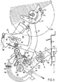
- the sequence of the switching mechanism 34 is released, pivots the locking arm 37 with the catch claw 39, controlled by a link 44 on the switching segment 10 and a lever arm 36 on the locking arm 37 in engagement with the stylus 86 of the slide 85 and locks the test disk 83 in a time-released position.
- the screw 87 with the screw shaft is simultaneously in drive connection with a securing flap 22, which is pivotably mounted on the rear plate 76, and pivots the securing flap 22 out of a locking position set with a torsion spring 45 and gives an adjustment segment pivotably mounted on the rear plate 76 19 free to carry out a parking time specification.
- the test disk 83 is not in a position locked by the fan claw 39 for a usable coin 11, the securing flap 22 is positioned under the stop 46 on the setting segment 19 and prevents any time-setting movement of the setting segment 19 in the clockwise direction according to FIG. 8.
- the catch claw 39 consists of a locking lug 47 which is formed in one piece on the locking arm 37 and an adjustable locking lug 38 which can be inserted into an elongated slot 38/1.
- the adjustable locking lug 38 increases the claw width to several Tolerance levels adjustable, so that the diameter tolerance range of the coins 11 for the fan claw area can also be adjusted.
- a significant relief for a predisposition to a setting for certain coins 11 is achieved in that, at regular intervals, setting markings 82 are provided on the circumference of the test disk 83, which represent a relationship to the setting of a tab 85 for a specific coin diameter and thus a placement and corresponding setting enable the test disk 83 to a predetermined coin diameter.
- the adjustment segment 19, which is pivotably mounted on the rear plate 76 and which is provided for converting the locked position of the test disk 83 into a corresponding parking time specification on the basis of a usable coin 11, has a switching tooth 60.
- a pinion 13 arranged on the switching segment 10 and locked by means of a friction spring 62 drives the setting segment 19 against a return spring 63.
- a stop cam 61 is provided which, when the setting segment 19 is driven clockwise as shown in FIGS. 5 and 8, strikes the screw 87 of a slide 85 of the locked test disk 83 to limit a setting angle assigned to the coin 11 entered.
- a crossing of the switching segment 10 beyond the assigned setting angle of the setting segment 19 remains ineffective by subsequently overcoming the friction on the pinion 13 on the support of the setting segment 19 on the screw 87.
- a blocking of the process is prevented by the pinion when an increased torque occurs. 13 rotated by a tooth pitch and thus comes out of engagement with the switching tooth 60.
- the switching segment 10 has a link guide 44, into which a control finger 48 is immersed on a lever arm 36 of the locking arm 37 and at the same time with the locking arm 37 a control lever integrally connected to it 49 and a control arm 51 pivoted to unlock the release lever 27 and the setting segment 19.
- a lug 52 of the release lever 27 is released during the running phase and the latter, driven by the spring 33, can rotate clockwise (FIG. 5).
- a locking bracket 53 on the release lever 27 is controlled out of engagement with a regulator gear 81 on the rear plate 76.
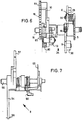
- actuating the rotary knob 2 also pivots the elevator segment 18, which is firmly connected to the switching segment 10.
- a first and a second tooth segment (64, 65) are arranged on the elevator segment 18, of which the first tooth segment 64 engages with the regulator gear 81 for controlled control of the switching mechanism sequence and the second tooth segment 65 with an elevator wheel 92 (FIGURES 3 and 4) one Time drive 91 is in drive connection.
- the elevator wheel 92 is rotatably mounted on a drive shaft 96.
- An axially displaceable crown gear 98 which has locking teeth (99) and is entrained in the direction of the elevator by the elevator wheel 92, which also has locking teeth 99, is also connected to the drive shaft 96 in a rotationally fixed manner.
- the drive shaft 96 rotates and pulls a drive spring (not shown in more detail) over two elevator gearwheels 100, 101, which are designed as a change gear set, by the rotary knob 2 during the elevator process.
- a drive spring (not shown in more detail) over two elevator gearwheels 100, 101, which are designed as a change gear set, by the rotary knob 2 during the elevator process.
- the timing drive 91 is engaged via a drive shaft 109 and a gear 108, further via a transmission gear, consisting of two gears 107 and 106, which are rotatably mounted on the back plate 76, with a gear 102, which is connected to the time slice 105 via a friction is.
- the time drive 91 drives the time slice 105 back in time from a parking time setting back to the basic position via the transmission chain explained above.
- the time is set by the setting segment 19, which after its release runs through a certain angular path until it rests on the test disk 83 with a stop cam 61 of a screw 87.
- the adjustment segment 19 has a toothed segment 72 which is in engagement with a ratchet 112 (FIGURE 8).
- a ratchet 112 FIG. 8
- the switching wheel 112 and with it a switching pawl 113 arranged on the switching wheel 112 are adjusted.
- the switching wheel 112 is loosely seated on a common axis 115 with the time slice 105.
- a replaceable one is on the time slice 105
- Switching comb 110 screwed tightly, in which the pawl 113 engages to set a time.
- the time slice 105 is adjustable due to a friction connection to the gear 108.
- the locking segment 3 is provided with a control cam 66 which controls a double-acting pawl 20 driven by a spring 68 via a lever arm 67 during the winding and return movement of the rotary knob 2 in the correct phase.
- a locking arm 69 on the pawl 20 holds the test segment 54 in the coin value checking position via the coupling bush 50.
- a resilient pawl arm 70 is provided on the pawl 20, which blocks the retraction of the locking arm 37 with the fan claw 39 and does not release it into a locked position of a set stylus 86 until the end of the elevator phase.
- the pawl 20 is pivotally mounted on a pin 73 on the front plate 1.
- the locking segment 3 protrudes a boom 74 in connection vert a lever 75 which is pivotally mounted on the front plate 1 and which engages in a fault display plate 23 which can be controlled in the display field, such that when the closing segment 3 moves from the starting position over the entire winding and returning process of the switching mechanism 34 the fault indicator plate 23 remains visible in the display panel.
Claims (20)
Applications Claiming Priority (2)
| Application Number | Priority Date | Filing Date | Title |
|---|---|---|---|
| DE3404752 | 1984-02-10 | ||
| DE3404752A DE3404752C2 (de) | 1984-02-10 | 1984-02-10 | Manuell betätigbare, selbstkassierende Parkuhr |
Publications (3)
| Publication Number | Publication Date |
|---|---|
| EP0152034A2 EP0152034A2 (fr) | 1985-08-21 |
| EP0152034A3 EP0152034A3 (en) | 1987-10-14 |
| EP0152034B1 true EP0152034B1 (fr) | 1990-04-11 |
Family
ID=6227343
Family Applications (1)
| Application Number | Title | Priority Date | Filing Date |
|---|---|---|---|
| EP85101088A Expired - Lifetime EP0152034B1 (fr) | 1984-02-10 | 1985-02-02 | Parcmètre auto-encaissant actionné manuellement |
Country Status (3)
| Country | Link |
|---|---|
| US (1) | US4807737A (fr) |
| EP (1) | EP0152034B1 (fr) |
| DE (2) | DE3404752C2 (fr) |
Families Citing this family (2)
| Publication number | Priority date | Publication date | Assignee | Title |
|---|---|---|---|---|
| US5400803A (en) * | 1992-07-22 | 1995-03-28 | Tracy Medical Resources, Inc. | Apparatus for support or positional treatment |
| US5507378A (en) * | 1994-11-03 | 1996-04-16 | Tricom Corporation | Coin box receptacle |
Family Cites Families (18)
| Publication number | Priority date | Publication date | Assignee | Title |
|---|---|---|---|---|
| US2603288A (en) * | 1952-07-15 | Coin-controlled timing apparatus | ||
| US2633960A (en) * | 1948-01-14 | 1953-04-07 | Duncan Parking Meter Corp | Coin-handling apparatus |
| US3026983A (en) * | 1953-03-30 | 1962-03-27 | Magee Hale Park O Meter Compan | Automatic parking meter |
| US3069839A (en) * | 1959-07-17 | 1962-12-25 | Johnson Sven Herbert | Parking meter |
| DE1474805B2 (de) * | 1965-09-03 | 1970-11-05 | Kienzle Apparate Gmbh, 7730 Villingen | Selbstkassierender Mietzeitmesser, insbesondere Parkuhr |
| SE312248B (fr) * | 1966-04-01 | 1969-07-07 | Cale Ind Ab | |
| DE1474749A1 (de) * | 1966-04-19 | 1969-07-24 | Duncan Parking Meter Corp | Parkuhr |
| DE1574225B1 (de) * | 1967-07-20 | 1972-01-13 | Kinzle App Gmbh | Parkuhr |
| US3506102A (en) * | 1967-12-19 | 1970-04-14 | Rockwell Mfg Co | Manual parking meter |
| DE2002468A1 (de) * | 1970-01-21 | 1971-07-29 | Kienzle Apparate Gmbh | Muenzbetaetigte Parkuhr fuer mehrere Tarife |
| DE2037055B2 (de) * | 1970-07-25 | 1972-01-20 | Kienzle Apparate GmbH, 7730 Villin | Muenzpruefeinrichtung fuer parkuhren |
| US3782519A (en) * | 1972-09-11 | 1974-01-01 | Qonaar Corp | Coin controlled meter construction |
| US3913718A (en) * | 1974-03-14 | 1975-10-21 | Qonaar Corp | Parking meter with increased winding capacity |
| DE2445204C2 (de) * | 1974-09-21 | 1978-12-14 | Kienzle Apparate Gmbh, 7730 Villingen-Schwenningen | Münzprüfeinrichtung für Parkuhren |
| DE2741474C2 (de) * | 1977-09-15 | 1982-02-18 | Vdo Adolf Schindling Ag, 6000 Frankfurt | Selbstkassierende Zeitkontrollvorrichtung, insbesondere Parkzeituhr |
| DE2949658A1 (de) * | 1979-12-11 | 1981-06-19 | Kienzle Apparate Gmbh, 7730 Villingen-Schwenningen | Muenzpruefeinrichtung fuer parkuhren |
| DE3314077A1 (de) * | 1983-04-19 | 1984-10-25 | Kienzle Apparate Gmbh, 7730 Villingen-Schwenningen | Einrichtung zur einstellung eines bestimmten zeitabschnittes in einem selbstkassierenden zeitschaltwerk |
| DE3411347A1 (de) * | 1984-03-28 | 1985-10-10 | Kienzle Apparate Gmbh, 7730 Villingen-Schwenningen | Vorrichtung zur pruefung der magnetischen eigenschaft einer muenze |
-
1984
- 1984-02-10 DE DE3404752A patent/DE3404752C2/de not_active Expired
-
1985
- 1985-02-02 DE DE8585101088T patent/DE3577153D1/de not_active Expired - Lifetime
- 1985-02-02 EP EP85101088A patent/EP0152034B1/fr not_active Expired - Lifetime
-
1987
- 1987-01-27 US US07/008,076 patent/US4807737A/en not_active Expired - Fee Related
Also Published As
| Publication number | Publication date |
|---|---|
| US4807737A (en) | 1989-02-28 |
| DE3404752A1 (de) | 1985-09-12 |
| EP0152034A2 (fr) | 1985-08-21 |
| DE3577153D1 (de) | 1990-05-17 |
| DE3404752C2 (de) | 1986-12-11 |
| EP0152034A3 (en) | 1987-10-14 |
Similar Documents
| Publication | Publication Date | Title |
|---|---|---|
| DE3602291A1 (de) | Muenzausgabevorrichtung | |
| DE1815601B2 (de) | Parkzeituhr | |
| EP0152034B1 (fr) | Parcmètre auto-encaissant actionné manuellement | |
| DE3314077C2 (fr) | ||
| DE2345409C3 (de) | Vorrichtung zum Zumessen eines Zeitabschnitts nach Münzeinwurf, insbesondere Parkuhr | |
| DE728554C (de) | Muenzwerk fuer Selbstverkaeufer fuer Elektrizitaet, Gas, Wasser o. dgl. | |
| DE2365544C3 (de) | Zeitvorgabewerk für handeinstellbare Mietzeitmesser | |
| DE947900C (de) | Gebuehrenzaehler in Fernmeldeanlagen, insbesondere Fernsprechanlagen | |
| CH462767A (de) | Elektrisches Bügeleisen mit einem schwenkbaren Schnureinführungsteil | |
| DE1474805A1 (de) | Selbstkassierender Mietzeitmesser,insbesondere Parkuhr | |
| DE2323567C3 (de) | Selbstkassierender Mietzeitmesser | |
| DE1574004B2 (de) | Vorrichtung zum abtasten der stellung mehrerer mit steuerkurven versehenen ziffernrollen eines vorwahlzaehlers | |
| DE376513C (de) | Vorrichtung zur selbsttaetigen Ausloesung von Drahtausloesern photographischer Verschluesse nach einstellbarer Zeit | |
| WO1998012608A1 (fr) | Dispositif pour ajuster l'aiguille des minutes d'une montre comportant au moins une aiguille des minutes et une trotteuse | |
| DE529573C (de) | Sparuhr | |
| CH716793A2 (de) | Weckerauslösevorrichtung für eine Uhr. | |
| DE974088C (de) | Selbstkassierende Parkzeituhr | |
| DE2365539C3 (de) | Zeitvorgabeeinrichtung für einen handeinstellbaren Mietzeitmesser | |
| DE1474749C (de) | Parkzeitmesser mit Munzprufer | |
| DE1574178C (de) | Durch Münzen betätigtes Zeitkontrollgerät insbesondere Parkuhr | |
| DE2037036C3 (de) | Schließeinrichtung mit Münzkassiervorrichtung | |
| DE1474749B2 (fr) | ||
| DE1959383A1 (de) | Vorrichtung zur Vorausbezahlung einer beliebigen Groesse | |
| DE2365539A1 (de) | Zeitvorgabeeinrichtung fuer einen handeinstellbaren mietzeitmesser | |
| DE2365544A1 (de) | Zeitvorgabewerk fuer handeinstellbare mietzeitmesser |
Legal Events
| Date | Code | Title | Description |
|---|---|---|---|
| PUAI | Public reference made under article 153(3) epc to a published international application that has entered the european phase |
Free format text: ORIGINAL CODE: 0009012 |
|
| AK | Designated contracting states |
Designated state(s): CH DE FR GB LI SE |
|
| RAP1 | Party data changed (applicant data changed or rights of an application transferred) |
Owner name: MANNESMANN KIENZLE GMBH |
|
| PUAL | Search report despatched |
Free format text: ORIGINAL CODE: 0009013 |
|
| AK | Designated contracting states |
Kind code of ref document: A3 Designated state(s): CH DE FR GB LI SE |
|
| 17P | Request for examination filed |
Effective date: 19880203 |
|
| 17Q | First examination report despatched |
Effective date: 19880504 |
|
| GRAA | (expected) grant |
Free format text: ORIGINAL CODE: 0009210 |
|
| AK | Designated contracting states |
Kind code of ref document: B1 Designated state(s): CH DE FR GB LI SE |
|
| REF | Corresponds to: |
Ref document number: 3577153 Country of ref document: DE Date of ref document: 19900517 |
|
| ET | Fr: translation filed | ||
| GBT | Gb: translation of ep patent filed (gb section 77(6)(a)/1977) | ||
| PLBE | No opposition filed within time limit |
Free format text: ORIGINAL CODE: 0009261 |
|
| STAA | Information on the status of an ep patent application or granted ep patent |
Free format text: STATUS: NO OPPOSITION FILED WITHIN TIME LIMIT |
|
| 26N | No opposition filed | ||
| EAL | Se: european patent in force in sweden |
Ref document number: 85101088.4 |
|
| PGFP | Annual fee paid to national office [announced via postgrant information from national office to epo] |
Ref country code: GB Payment date: 19960115 Year of fee payment: 12 |
|
| PGFP | Annual fee paid to national office [announced via postgrant information from national office to epo] |
Ref country code: FR Payment date: 19960116 Year of fee payment: 12 |
|
| PGFP | Annual fee paid to national office [announced via postgrant information from national office to epo] |
Ref country code: SE Payment date: 19960125 Year of fee payment: 12 |
|
| PGFP | Annual fee paid to national office [announced via postgrant information from national office to epo] |
Ref country code: CH Payment date: 19960126 Year of fee payment: 12 |
|
| PGFP | Annual fee paid to national office [announced via postgrant information from national office to epo] |
Ref country code: DE Payment date: 19960321 Year of fee payment: 12 |
|
| PG25 | Lapsed in a contracting state [announced via postgrant information from national office to epo] |
Ref country code: GB Effective date: 19970202 |
|
| PG25 | Lapsed in a contracting state [announced via postgrant information from national office to epo] |
Ref country code: SE Effective date: 19970203 |
|
| PG25 | Lapsed in a contracting state [announced via postgrant information from national office to epo] |
Ref country code: LI Effective date: 19970228 Ref country code: CH Effective date: 19970228 |
|
| GBPC | Gb: european patent ceased through non-payment of renewal fee |
Effective date: 19970202 |
|
| REG | Reference to a national code |
Ref country code: CH Ref legal event code: PL |
|
| PG25 | Lapsed in a contracting state [announced via postgrant information from national office to epo] |
Ref country code: FR Effective date: 19971030 |
|
| PG25 | Lapsed in a contracting state [announced via postgrant information from national office to epo] |
Ref country code: DE Effective date: 19971101 |
|
| EUG | Se: european patent has lapsed |
Ref document number: 85101088.4 |
|
| REG | Reference to a national code |
Ref country code: FR Ref legal event code: ST |