EP0146869B1 - Vorrichtung zum Zwischenstapeln von Schneidegut - Google Patents
Vorrichtung zum Zwischenstapeln von Schneidegut Download PDFInfo
- Publication number
- EP0146869B1 EP0146869B1 EP84115166A EP84115166A EP0146869B1 EP 0146869 B1 EP0146869 B1 EP 0146869B1 EP 84115166 A EP84115166 A EP 84115166A EP 84115166 A EP84115166 A EP 84115166A EP 0146869 B1 EP0146869 B1 EP 0146869B1
- Authority
- EP
- European Patent Office
- Prior art keywords
- board
- stack
- boards
- work
- abutments
- Prior art date
- Legal status (The legal status is an assumption and is not a legal conclusion. Google has not performed a legal analysis and makes no representation as to the accuracy of the status listed.)
- Expired
Links
Images
Classifications
-
- B—PERFORMING OPERATIONS; TRANSPORTING
- B65—CONVEYING; PACKING; STORING; HANDLING THIN OR FILAMENTARY MATERIAL
- B65H—HANDLING THIN OR FILAMENTARY MATERIAL, e.g. SHEETS, WEBS, CABLES
- B65H33/00—Forming counted batches in delivery pile or stream of articles
- B65H33/16—Forming counted batches in delivery pile or stream of articles by depositing articles in batches on moving supports
- B65H33/18—Forming counted batches in delivery pile or stream of articles by depositing articles in batches on moving supports with separators between adjacent batches
-
- Y—GENERAL TAGGING OF NEW TECHNOLOGICAL DEVELOPMENTS; GENERAL TAGGING OF CROSS-SECTIONAL TECHNOLOGIES SPANNING OVER SEVERAL SECTIONS OF THE IPC; TECHNICAL SUBJECTS COVERED BY FORMER USPC CROSS-REFERENCE ART COLLECTIONS [XRACs] AND DIGESTS
- Y10—TECHNICAL SUBJECTS COVERED BY FORMER USPC
- Y10S—TECHNICAL SUBJECTS COVERED BY FORMER USPC CROSS-REFERENCE ART COLLECTIONS [XRACs] AND DIGESTS
- Y10S414/00—Material or article handling
- Y10S414/10—Associated with forming or dispersing groups of intersupporting articles, e.g. stacking patterns
- Y10S414/101—Associated with forming or dispersing groups of intersupporting articles, e.g. stacking patterns with article-supporting fluid cushion
-
- Y—GENERAL TAGGING OF NEW TECHNOLOGICAL DEVELOPMENTS; GENERAL TAGGING OF CROSS-SECTIONAL TECHNOLOGIES SPANNING OVER SEVERAL SECTIONS OF THE IPC; TECHNICAL SUBJECTS COVERED BY FORMER USPC CROSS-REFERENCE ART COLLECTIONS [XRACs] AND DIGESTS
- Y10—TECHNICAL SUBJECTS COVERED BY FORMER USPC
- Y10S—TECHNICAL SUBJECTS COVERED BY FORMER USPC CROSS-REFERENCE ART COLLECTIONS [XRACs] AND DIGESTS
- Y10S414/00—Material or article handling
- Y10S414/10—Associated with forming or dispersing groups of intersupporting articles, e.g. stacking patterns
- Y10S414/112—Group formed or dispensed by reversible apparatus
Definitions
- the invention relates to a device for. Intermediate stacking of material to be cut, in which the material to be cut is fed from the work table to a first work station, in particular a vibrating table, to a stack lift, on which the material to be cut is stored in part stacks with the intermediate storage of boards and from there to the work table of a second work station, in particular a cutting table of a cutting machine , is fed.
- a first work station in particular a vibrating table
- a stack lift on which the material to be cut is stored in part stacks with the intermediate storage of boards and from there to the work table of a second work station, in particular a cutting table of a cutting machine , is fed.
- Such a device is known from DE-PS-1 244 711.
- the material to be cut is shaken on a vibrating table before the cutting process, in order to thereby align the individual sheets precisely with one another.
- the material to be cut is stacked on a stack lift.
- the partial stacks lie one above the other on the stack lift, boards being arranged between the individual partial stacks. Moving the partial stack from the vibrating table to the boards or from the boards to the cutting table is done in a simple manner in that the boards are designed as air boards, d. H. they are provided with an air supply and on the surface facing the partial stacks with air outlet nozzles.
- the object of the invention is to provide a device with which it is possible to stack material to be cut without the partial stacks being shifted during loading or unloading.
- movable stops are arranged below the level of the support surfaces of the work tables, the stops being in the retracted position outside the displacement formed when the boards are raised and lowered, engaging in the extended position in the extended position and when a board is placed on the board the support surface of the board forms a level with the support surfaces of the work tables on the extended stops.
- the stops When loading the stack lift, it is lowered to such an extent that a transport pallet lying thereon and / or partial stacks already deposited are located below the stops. Then the stops are moved to the extended position and the board is placed on them. The stops hold the board in this position, in which the support surface of the board forms a plane with the support surface of the work tables. The partial stack to be put down is pushed onto the board and then the stack lift is raised so that the top board with the now placed partial stack relieves the stops. The stops are moved to their retracted position, i.e. H.
- the stack lift is lowered to such an extent that the surface of the last stacked part lies below the stops and forms an intermediate space to the underside of the board to be placed later. Finally, the stops for receiving the next board and a further partial stack are moved into the extended position.
- the stack lift When processing the partial stack, the stack lift is raised so far that the stops can be moved under the board carrying the uppermost partial stack.
- the stack lift is lowered to such an extent that the top board rests on the stops and there is a gap between the underside of the top board and the surface of the stack of taps below it, or in the final stage of the workflow there is a gap between the underside of the top air board and the surface of the Transport pallet forms.
- the prepared partial stack is then fed to the second work station, the board is removed and the stops are moved into the retracted position.
- the next partial stack is then raised by the stack lift.
- the stops according to the invention thus have the task of ensuring the horizontal position of the board lying on them and the flushness of the contact surface of the board with the contact surfaces of the work tables. While the stack lift usually takes over the carrying function for the partial stack and the boards in between, this carrying function for the top board and the partial stack located on it is performed by the stops. By separating the top board from the remaining stack during loading or unloading, it is prevented that the partial stack under the top board moves.
- the stops can be attached to both the workstations and the stack lift.
- the stops are expediently designed as flaps, one end of which is pivotally attached to the underside of the work tables of the work stations and the free end of which serves to support the board. If the flaps are arranged on the underside of the work tables, the stack lift is particularly space-saving. To pivot the flap, force elements should also be on the underside of the workbenches, in particular whose hydraulic power cylinder can be arranged.
- the width of the board i. H. perpendicular to the direction of displacement of the partial stack on the board, several flaps with force elements can be provided.
- stops are also advisable to arrange the stops not on the underside of the work tables, but rather on a swivel.
- thorn-like projections could extend under the board in the extended position or engage in corresponding recesses in the board and thus hold the board in a flush position with the work tables.
- the displacement of the extensions from the retracted to the extended position and back would also be effected by force elements.
- the boards advantageously have supports on their underside, the length of the individual supports being the same but greater than the height of the partial stack lying under the board.
- the use of such boards with supports is indicated when the individual partial stacks consist of lightweight, high-quality single sheets. In this case, the load of all partial stacks does not rest on the lower partial stack, but the boards are supported on the other boards.
- the boards In order to ensure that the partial stacks are easily pushed over, the boards should be designed as air boards with air inlet and outlet openings.
- the stacking lift advantageously has wheels for moving. While the partial stack lying on the board is being moved to the next work station when the stops are extended, or while partial stacks are being transported from one work station over the board to the other work station, the stack lift can leave the work area and bring in new material.
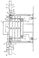
- a stacking lift 3 is located between a shaking table 1, which is only partially shown, and a cutting table 2, which is also only partially shown, of a paper cutting machine.
- the partially raised lifting fork 5 of the stack lift 4 passes through a pallet 6 on which the material to be cut is stored with the interposition of air boards 7a to 7e to partial stacks 8a to 8d.
- a plurality of flaps 13 are arranged pivotably about the joints 14 perpendicular to the plane of the drawing.
- hydraulic power cylinders 15 also arranged on the undersides 9 and 11 engage with their piston rods 16 on angle pieces 17 arranged on the flaps 13.
- the arrangement of the flaps on the undersides 9 and 11 and the dimension of the flaps with the supports 18 arranged at the free end of the flap is such that, when the flaps 13 are pivoted out, as shown in the figure, the air board 7e can be placed on the supports 18 , wherein the support surface 19 forms a plane with the support surfaces 20 and 21 of the worktops 10 and 12.
- the air inlet opening of the air board 7e which is not shown in any more detail, is connected to an air bell 22, which is shown schematically. An air flow is blown through this into the board 7e and then through air outlet openings arranged on the top of the board.
- the air film forming above the air board 7e makes it easier to push the partial stack 8e over from the support surface 20 to the air board 7e.
- the lifting fork 5 of the stack lift 3 is moved so far down that a gap remains between the underside of the air board 7e and the surface of the partial stack 8d. This ensures that the upper individual sheets of the partial stack 8d cannot be moved during the displacement of the partial stack 8e onto the air board 7e.
- the lifting fork 5 of the stack lift 3 is raised slightly in order to relieve the flaps 13.
- the air board 7e comes to a standstill with its four supports 23 on the air board 7d, whereby it does not touch the partial stack 8d located on the air board 7d.
- the other air boards 7a to 7d do not have such supports 23, the board 7b lies directly on the partial stack 8a, the board 7c directly on the partial stack 8b and the board 7d directly on the partial stack 8c.
Landscapes
- Pile Receivers (AREA)
- Sheets, Magazines, And Separation Thereof (AREA)
- Details Of Cutting Devices (AREA)
- Stacking Of Articles And Auxiliary Devices (AREA)
- Warehouses Or Storage Devices (AREA)
- Collation Of Sheets And Webs (AREA)
- Forming Counted Batches (AREA)
Description
- Die Erfindung betrifft eine Vorrichtung zum . Zwischenstapeln von Schneidegut, bei der das Schneidegut von dem Arbeitstisch einer ersten Arbeitsstation, insbesonderen einem Rütteltisch, einem Stapellift zugeführt wird, auf dem das Schneidegut unter Zwischenlagerung von Brettern zu Teilstapeln gelagert wird und von dort dem Arbeitstisch einer zweiten Arbeitsstation, insbesondere einem Schneidetisch einer Schneidemaschine, zugeführt wird.
- Eine derartige Vorrichtung ist aus der DE-PS-1 244 711 bekannt. Bei dieser wird das Schneidegut vor dem Schneidevorgang auf einem Rütteltisch gerüttelt, um dadurch die einzelnen Blätter genau zueinander auszurichten. Im Anschluß an den Rüttelvorgang erfolgt eine Zwischenstapelung des Schneideguts auf einem Stapellift. Die Teilstapel liegen dabei auf dem Stapellift übereinander, wobei zwischen den einzelnen Teilstapeln Bretter angeordnet sind. Das Verschieben der Teilstapel vom Rütteltisch auf die Bretter bzw. von den Brettern auf den Schneidetisch erfolgt in einfacher Art und Weise dadurch, daß die Bretter als Luftbretter ausgebildet sind, d. h. sie sind mit einer Luftzufuhr sowie auf der den aufliegenden Teilstapeln zugewandten Oberfläche mit Luftaustrittsdüsen versehen.
- Eine derartige Vorrichtung weist jedoch den Nachteil auf, daß es durch ungleichmäßig hohes Auftragen der einen Teilstapel bildenden Einzelbogen dazu kommen kann, daß das auf dem Teilstapel aufliegende Luftbrett schief liegt. Eine Bündigkeit des Luftbrettes mit den Auflageflächen der Arbeitstische ist damit nicht mehr gewährleistet. Beim Beschicken oder Entladen des auf dem obersten Luftbrett liegenden Teilstapels wird der unter diesem Brett liegende Teilstapel verschoben. Beim Schneiden dieses Teilstapels können sich dann keine exakten Schnittgrößen mehr ergeben.
- Aufgabe der Erfindung ist es, eine Vorrichtung zu schaffen, mit der es möglich ist, Schneidegut zu stapeln, ohne daß beim Beschicken oder Entladen die Teilstapel in sich verschoben werden.
- Gelöst wird die Aufgabe dadurch, daß unterhalb des Niveaus der Auflageflächen der Arbeitstische bewegliche Anschläge angeordnet sind, wobei die Anschläge sich in eingefahrener Position außerhalb des beim Heben und Senken der Bretter gebildeten Hubraumes befinden, in ausgefahrener Position in den Hubraum eingreifen und beim Auflegen eines Brettes auf die ausgefahrenen Anschläge die Auflagefläche des Brettes mit den Auflageflächen der Arbeitstische eine Ebene bildet.
- Beim Beschicken des Stapelliftes wird dieser soweit abgesenkt, daß eine auf diesem liegende Transportpalette und/oder bereits abgelegte Teilstapel unterhalb der Anschläge sich befinden. Sodann werden die Anschläge in die ausgefahrene Position bewegt und das Brett auf diese gelegt. Die Anschläge halten das Brett in dieser Position, in der die Auflagefläche des Brettes mit der Auflagefläche der Arbeitstische eine Ebene bildet. Der abzulegende Teilstapel wird auf das Brett geschoben und anschließend der Stapellift soweit angehoben, daß das oberste Brett mit dem jetzt abgelegten Teilstapel die Anschläge entlastet. Die Anschläge werden in ihre eingefahrene Position bewegt, d. h. sie befinden sich außerhalb des beim Heben und Senken der Bretter gebildeten Hubraumes, der Stapellift wird soweit abgesenkt, daß die Oberfläche des zuletzt abgelegten Teilstapels unterhalb der Anschläge liegt und einen Zwischenraum zur Unterseite des später aufzulegenden Brettes bildet. Schließlich werden die Anschläge zur Aufnahme des nächsten Brettes sowie eines weiteren Teilstapels in die ausgefahrene Position bewegt.
- Beim Abarbeiten der Teilstapel wird der Stapellift soweit hochgefahren, daß sich die Anschläge unter das den obersten Teilstapel tragende Brett bewegen lassen. Der Stapellift wird soweit abgesenkt, daß das oberste Brett auf den Anschlägen aufliegt und sich ein Zwischenraum zwischen der Unterseite des obersten Brettes und der Oberfläche des darunter bereitgehaltenen Teifstapels bzw. im Endstadium des Arbeitsablaufs sich ein Zwischenraum zwischen der Unterseite des obersten Luftbretts und der Oberfläche der Transportpalette bildet. Der bereitgelegte Teilstapel wird sodann der zweiten Arbeitsstation zugeführt, das Brett herausgenommen und die Anschläge in die eingefahrene Position bewegt. Es erfolgt dann das Hochfahren des nächsten Teilstapels durch den Stapellift.
- Die erfindungsgemäßen Anschläge haben somit in ihrer ausgefahrenen Position die Aufgabe, die horizontale Lage des auf ihnen liegenden Brettes sowie die Bündigkeit der Auflagefläche des Brettes mit den Auflageflächen der Arbeitstische zu gewährleisten. Während üblicherweise der Stapellift die Tragefunktion für die Teilstapel sowie die dazwischen befindlichen Bretter übernimmt, wird diese Tragefunktion für das oberste Brett sowie den darauf befindlichen Teilstapel durch die Anschläge wahrgenom Durch das Trennen des obersten Brettes vom Reststapel während des Beschickens oder Entladens wird verhindert, daß sich der unter dem obersten Brett liegende Teilstapel verschiebt.
- Die Befestigung der Anschläge kann sowohl an den Arbeitsstationen als auch am Stapellift erfolgen. Zweckmäßig sind die Anschläge als Klappen ausgebildet, deren eines Ende an der Unterseite der Arbeitstische der Arbeitsstationen schwenkbar befestigt ist und desse freies Ende der Auflage des Brettes dient. Für den Fall der Anordnung der Klappen an der Unterseite der Arbeitstische ergibt sich eine besonders raumsparende Gestaltung des Stapellifts. Zum Verschwenken der Klappe sollten ferner an der Unterseite der Arbeitstische Kraftelemente, insbesondere hydraulische Kraftzylinder, angeordnet sein.
- Um eine stabile Lage des Brettes bezüglich der Auflageflächen der Tische zu gewährleisten, sollten über die Breite des Brettes, d. h. senkrecht zur Verschieberichtung der Teilstapel auf dem Brett, mehrere Klappen mit Kraftelementen vorgesehen sein.
- Es bietet sich jedoch gleichfalls an, die Anschläge nicht verschwenkbar, sondern verschiebbar an der Unterseite der Arbeitstische anzuordnen. In einem solchen Fall könnten dornenartig gestaltete Fortsätze in ausgefahrener Position das Brett untergreifen bzw. in entsprechende Ausnehmungen im Brett eingreifen und derart das Brett in bündiger Position zu den Arbeitstischen halten. Die Verschiebung der Fortsätze von der eingefahrenen in die ausgefahrene Position und zurück würde gleichfalls durch Kraftelemente bewirkt.
- Es ist schließlich möglich, die Anschläge nicht an den Arbeitsstationen, sondern am Stapellift verschwenkbar oder verschiebbar anzuordnen.
- Vorteilhaft weisen die Bretter an ihrer Unterseite Stützen auf, wobei die Länge der einzelnen Stützen gleich, jedoch größer als die Höhe des unter dem Brett liegenden Teilstapels ist. Der Einsatz derartiger Bretter mit Stützen ist dann angezeigt, wenn die einzelnen Teilstapel aus leichtgewichtigen, qualitativ hochwertigen Einzelbogen bestehen. In diesem Fall ruht nicht die Last aller Teilstapel auf dem unteren Teilstapeln, sondern es stützen sich die Bretter auf den anderen Brettern ab.
- Um ein leichtes Überschieben der Teilstapel zu gewährleisten, sollten die Bretter als Luftbretter mit Luftein- und -ausblasöffnungen ausgebildet sein.
- Vorteilhaft weist der Stapellift Räder zum Verfahren auf. Noch während bei ausgefahrenen Anschlägen der auf dem Brett liegende Teilstapel zur nächsten Arbeitsstation verfahren wird, oder während Teilstapel von einer Arbeitsstation über das Brett zur anderen Arbeitsstation befördert werden, kann der Stapellift den Arbeitsbereich verlassen und neues Material heranschaffen.
- Weitere Merkmale der Erfindung sind in der Zeichnung der Figur dargestellt.
- Diese zeigt einen Längsschnitt durch die Vorrichtung. Zwischen einem teilweise nur dargestellten Rütteltisch 1 sowie einem gleichfalls nur teilweise dargestellten Schneidetisch2 einer Papierschneidemaschine befindet sich ein Stapellift 3. Dieser weist an seiner Unterseite Räder 4 zum Verfahren auf. Die teilweise angehobene Hubgabel 5 des Stapellifts 4 durchgreift eine Palette 6, auf der das Schneidegut unter Zwischenlage von Luftbrettern 7a bis 7e zu Teilstapein 8a bis 8d gelagert wird.
- An der Unterseite 9 der Arbeitsplatte 10 des Rütteltisches 1 sowie der Unterseite 11 der Arbeitsplatte 12 des Schneidetisches 2 sind senkrecht zur Zeichenebene mehrere Klappen 13 um die Gelenke 14 schwenkbar angeordnet. Dazu greifen gleichfalls an den Unterseiten 9 und 11 angeordnete hydraulische Kraftzylinder 15 mit ihren Kolbenstangen 16 an an den Klappen 13 angeordneten Winkelstücken 17 an.
- Die Anordnung der Klappen an den Unterseiten 9 und 11 sowie die Abmessung der Klappen mit den am freien Klappenende angeordneten Auflagen 18 ist derart, daß in ausgeschwenktem Zustand der Klappen 13, wie in der Figur dargestellt, das Luftbrett 7e auf die Auflagen 18 gelegt werden kann, wobei die Auflagefläche 19 eine Ebene mit den Auflageflächen 20 und 21 der Arbeitsplatten 10 und 12 bildet. In der in der Figur dargestellten Position steht die nicht näher dargestellte Lufteintrittsöffnung des Luftbrettes 7e in Verbindung mit einer schematisch dargestellten Luftglocke 22. Durch diese wird ein Luftstrom in das Brett 7e und dann durch an der Oberseite des Brettes angeordnete Luftaustrittsöffnungen hindurchgeblasen. Der sich oberhalb des Luftbrettes 7e bildende Luftfilm erleichtert das Überschieben des Teilstapels 8e von der Auflagefläche 20 zum Luftbrett 7e.
- Bei ausgefahrenen Klappen 13 ist die Hubgabel 5 des Stapelliftes 3 soweit nach unten verfahren, daß zwischen der Unterseite des Luftbrettes 7e und der Oberfläche des Teilstapels 8d ein Zwischenraum verbleibt. Durch diesen ist gewährleistet, daß während des Verschiebens des Teilstapels 8e auf das Luftbrett 7e die oberen einzelnen Bogen des Teilstapels 8d nicht mit verschoben werden können.
- Nachdem der Teilstapel 8e sich auf dem Luftbrett 7e befindet, wird die Hubgabel 5 des Stapelliftes 3 geringfügig angehoben, um die Klappen 13 zu entlasten. Im Gegensatz zu den Luftbrettern 7a bis 7d kommt dabei das Luftbrett 7e mit seinen vier Stützen 23 auf dem Luftbrett 7d zum Stehen, wobei es den auf dem Luftbrett 7d befindlichen Teilstapel 8d nicht berührt. Im Unterschied dazu weisen die übrigen Luftbretter 7a bis 7d derartige Stützen 23 nicht auf, das Brett 7b liegt direkt auf dem Teilstapel 8a, das Brett 7c direkt auf dem Teilstapel 8b und das Brett 7d direkt auf dem Teilstapel 8c auf. Es ist jedoch gleichfalls möglich, alle Bretter mit oder ohne Stützen zu versehen.
- Nachdem die Klappen 13 entlastet sind, werden sie über die hydraulischen Kraftglieder 15 zurückgeschwenkt, so daß sie sich außerhalb des beim Heben und Senken der Bretter 7a bis 7e gebildeten Hubraumes befinden (Außenkontur des Hubraumes strichliert dargestellt).
- Das Einfügen weiterer Teilstapel in den Stapellift bzw. das Abarbeiten der Teilstapel aus dem Stapellift wurde bereits vorstehend erläutert.
Claims (9)
Priority Applications (1)
| Application Number | Priority Date | Filing Date | Title |
|---|---|---|---|
| AT84115166T ATE27439T1 (de) | 1983-12-14 | 1984-12-11 | Vorrichtung zum zwischenstapeln von schneidegut. |
Applications Claiming Priority (2)
| Application Number | Priority Date | Filing Date | Title |
|---|---|---|---|
| DE19838335816U DE8335816U1 (de) | 1983-12-14 | 1983-12-14 | Vorrichtung zum zwischenstapeln von schneidgut |
| DE8335816U | 1983-12-14 |
Publications (3)
| Publication Number | Publication Date |
|---|---|
| EP0146869A2 EP0146869A2 (de) | 1985-07-03 |
| EP0146869A3 EP0146869A3 (en) | 1985-07-31 |
| EP0146869B1 true EP0146869B1 (de) | 1987-05-27 |
Family
ID=6759824
Family Applications (1)
| Application Number | Title | Priority Date | Filing Date |
|---|---|---|---|
| EP84115166A Expired EP0146869B1 (de) | 1983-12-14 | 1984-12-11 | Vorrichtung zum Zwischenstapeln von Schneidegut |
Country Status (6)
| Country | Link |
|---|---|
| US (1) | US4613267A (de) |
| EP (1) | EP0146869B1 (de) |
| JP (2) | JPS60144276A (de) |
| AT (1) | ATE27439T1 (de) |
| DE (2) | DE8335816U1 (de) |
| ES (1) | ES8603785A1 (de) |
Cited By (1)
| Publication number | Priority date | Publication date | Assignee | Title |
|---|---|---|---|---|
| DE3613462A1 (de) * | 1986-04-22 | 1987-10-29 | Wolfgang Mohr | Vorrichtung zum be- und entladen eines stapellifts |
Families Citing this family (7)
| Publication number | Priority date | Publication date | Assignee | Title |
|---|---|---|---|---|
| FR2587311A1 (fr) * | 1985-09-18 | 1987-03-20 | Schauman | Procede et installation de manutention automatique et stockage temporaire de paquets empiles de produits semi-finis en feuilles. |
| US5256028A (en) * | 1986-07-23 | 1993-10-26 | Winski Ernest P | Process for handling material |
| DE3914598C2 (de) * | 1989-05-03 | 1994-05-19 | Focke & Co | Verfahren und Vorrichtung zum Abräumen von Gegenständen von einer Unterlage mit hohem Reibungswiderstand |
| DE3940190A1 (de) * | 1989-12-05 | 1991-06-06 | Kolbus Gmbh & Co Kg | Verfahren zum be- und entladen von paletten mit stapeln von flaechigen produkten und einrichtung zur durchfuehrung des verfahrens |
| US5562403A (en) * | 1991-02-11 | 1996-10-08 | Winski; Ernest P. | Load forming apparatus and methods |
| ES2112460T3 (es) * | 1993-10-05 | 1998-04-01 | Seemi | Procedimiento para la paletizacion de tramos de tubos de papel o de otros objetos similares e instalacion para la realizacion del mismo. |
| US6305500B1 (en) * | 1999-08-25 | 2001-10-23 | Maxtor Corporation | Material delivery system for clean room-like environments |
Family Cites Families (16)
| Publication number | Priority date | Publication date | Assignee | Title |
|---|---|---|---|---|
| US30742A (en) * | 1860-11-27 | Improvement in ordnance | ||
| US674262A (en) * | 1900-02-21 | 1901-05-14 | Garland H Duncan | Lumber-stacker. |
| US1225523A (en) * | 1915-02-27 | 1917-05-08 | Robert E Surles | Lumber-stacker. |
| US3146897A (en) * | 1962-01-11 | 1964-09-01 | Kalamazoo Paper Company | Paper pile separating and stacking transfer apparatus |
| DE1584410A1 (de) * | 1963-06-14 | 1970-01-22 | S I I Fornaci Magnetti S P A | Mechanische Einrichtung zur Automatisierung des Produktionsvorganges von Ziegeln |
| DE1244711B (de) * | 1965-06-12 | 1967-07-20 | Rudolf Mohr | Vorrichtung zum Stapeln von Schneidegut und selbsttaetigem Zufuehren an den Arbeitstisch, insbesondere von Papierschneidemaschinen |
| US3398841A (en) * | 1967-02-07 | 1968-08-27 | Mohr Rudolf | Apparatus for stacking material and automatically feeding the material to a worktable of a paper-cutting machine |
| USRE30742E (en) | 1968-02-11 | 1981-09-15 | Wyard Industries, Inc. | Container depalletizing apparatus |
| US3548995A (en) * | 1968-06-13 | 1970-12-22 | Sta Hi Corp | Controlled variable speed stacking device for publication conveyor |
| US3960374A (en) * | 1972-06-15 | 1976-06-01 | Harris-Intertype Corporation | Sheet delivery system |
| US3897877A (en) * | 1973-08-22 | 1975-08-05 | Goldco Industries | Apparatus for positioning and orienting palletized articles |
| CA975813A (en) * | 1974-09-06 | 1975-10-07 | Theodore E. O'brien | Apparatus for automatically stacking and compressing batts of compressible material |
| JPS5655166U (de) * | 1979-10-06 | 1981-05-14 | ||
| JPS6011676B2 (ja) * | 1980-04-10 | 1985-03-27 | 小森印刷機械株式会社 | 印刷機排紙部の紙流れ防止装置 |
| JPS5930620B2 (ja) * | 1981-05-21 | 1984-07-27 | 東洋ガラス機械株式会社 | 多重積層容器体からの容器取出移送装置 |
| JPS5811787U (ja) * | 1981-07-15 | 1983-01-25 | 株式会社日立製作所 | 行先表示装置 |
-
1983
- 1983-12-14 DE DE19838335816U patent/DE8335816U1/de not_active Expired
-
1984
- 1984-12-07 JP JP59257741A patent/JPS60144276A/ja active Pending
- 1984-12-10 US US06/679,745 patent/US4613267A/en not_active Expired - Fee Related
- 1984-12-11 EP EP84115166A patent/EP0146869B1/de not_active Expired
- 1984-12-11 AT AT84115166T patent/ATE27439T1/de not_active IP Right Cessation
- 1984-12-11 DE DE8484115166T patent/DE3463921D1/de not_active Expired
- 1984-12-14 ES ES538622A patent/ES8603785A1/es not_active Expired
-
1991
- 1991-09-27 JP JP1991099454U patent/JP2525234Y2/ja not_active Expired - Lifetime
Cited By (1)
| Publication number | Priority date | Publication date | Assignee | Title |
|---|---|---|---|---|
| DE3613462A1 (de) * | 1986-04-22 | 1987-10-29 | Wolfgang Mohr | Vorrichtung zum be- und entladen eines stapellifts |
Also Published As
| Publication number | Publication date |
|---|---|
| DE3463921D1 (en) | 1987-07-02 |
| US4613267A (en) | 1986-09-23 |
| EP0146869A3 (en) | 1985-07-31 |
| JP2525234Y2 (ja) | 1997-02-05 |
| JPS60144276A (ja) | 1985-07-30 |
| ES538622A0 (es) | 1986-01-16 |
| ES8603785A1 (es) | 1986-01-16 |
| ATE27439T1 (de) | 1987-06-15 |
| EP0146869A2 (de) | 1985-07-03 |
| DE8335816U1 (de) | 1984-04-26 |
| JPH081281U (ja) | 1996-08-13 |
Similar Documents
| Publication | Publication Date | Title |
|---|---|---|
| EP0077508B1 (de) | Verfahren und Vorrichtung zum Verpacken von palettierten Gutstapeln | |
| DE2440278C2 (de) | Vorrichtung zum Palettieren von Gegenständen | |
| DE10123326C1 (de) | Auslagevorrichtung für eine Bogen verarbeitende Maschine und Verfahren zum Auslegen von Bogen in einer Bogen verarbeitenden Maschine | |
| DE7908192U1 (de) | Stapelvorrichtung | |
| DE2952624A1 (de) | Vorrichtung zum gruppieren von gegenstaenden in stapelschichten zur beschickung von paletten | |
| EP0765827A1 (de) | Beschick- oder Stapelvorrichtung für plattenförmige Werkstücke | |
| EP0860253A2 (de) | Verfahren zur Herstellung von mehrlagigen Türrohlingen und Anlage zur Durchführung des Verfahrens | |
| EP0316568B1 (de) | Vorrichtung zum Abstapeln von Bögen | |
| DE2547149A1 (de) | Verfahren und vorrichtung zur herstellung von platten oder tafeln aus zellstoff bzw. faser- oder spanwerkstoff | |
| EP0146869B1 (de) | Vorrichtung zum Zwischenstapeln von Schneidegut | |
| DE2614558A1 (de) | Verfahren und vorrichtung zur herstellung palettenloser kollis | |
| DE3105237C2 (de) | Anlage zum Herstellung von vergüteten Spanplatten, Faserplatten u. dgl. | |
| DE19708125A1 (de) | Stapler | |
| EP0195992A2 (de) | Greifereinrichtung in einer Laminiervorrichtung | |
| DE4227726C2 (de) | Anlage zum Pressen von Laminaten | |
| DE2630094C2 (de) | Verfahren zur Trennung und Stapelung von gestanzten Bögen | |
| DE2626630C2 (de) | Verfahren und Gerät zur Trennung und Stapelung von gestanzten Bögen | |
| EP0298435B1 (de) | Einrichtung zum Fördern von Karton-Zuschnitten | |
| DE102006050648B3 (de) | Vorrichtung zum Umsetzen von Blechteilen zwischen zwei Pressen und zum Wechseln der Greifwerkzeuge | |
| DE19914357C2 (de) | Folien-Legeanlage zum wenigstens oberseitigen Belegen von Trägerplatten mit Folien | |
| DE2255103A1 (de) | Verfahren und vorrichtung zum beschicken von pressen | |
| DE9318897U1 (de) | Einrichtung zum Palettieren von Schlauchabschnitten | |
| DE3336937A1 (de) | Vorrichtung zum abnehmen einzelner scheibenfoermiger gegenstaende, insbesondere glasscheiben, von einem scheibenvorrat | |
| DE2736832A1 (de) | Verfahren zum kontinuierlichen auslegen von flaechigen formaten aus papier-, karton- und folienmaterial auf paletten | |
| DE3415189A1 (de) | Vorrichtung zur fugenvorbereitenden bearbeitung von raendern ebener rechteckiger bleche |
Legal Events
| Date | Code | Title | Description |
|---|---|---|---|
| PUAI | Public reference made under article 153(3) epc to a published international application that has entered the european phase |
Free format text: ORIGINAL CODE: 0009012 |
|
| PUAL | Search report despatched |
Free format text: ORIGINAL CODE: 0009013 |
|
| 17P | Request for examination filed |
Effective date: 19841224 |
|
| AK | Designated contracting states |
Designated state(s): AT BE CH DE FR GB IT LI LU NL SE |
|
| ITCL | It: translation for ep claims filed |
Representative=s name: MODIANO & ASSOCIATI S.R.L. |
|
| AK | Designated contracting states |
Designated state(s): AT BE CH DE FR GB IT LI LU NL SE |
|
| EL | Fr: translation of claims filed | ||
| TCNL | Nl: translation of patent claims filed | ||
| 17Q | First examination report despatched |
Effective date: 19860221 |
|
| GRAA | (expected) grant |
Free format text: ORIGINAL CODE: 0009210 |
|
| AK | Designated contracting states |
Kind code of ref document: B1 Designated state(s): AT BE CH DE FR GB IT LI LU NL SE |
|
| REF | Corresponds to: |
Ref document number: 27439 Country of ref document: AT Date of ref document: 19870615 Kind code of ref document: T |
|
| REF | Corresponds to: |
Ref document number: 3463921 Country of ref document: DE Date of ref document: 19870702 |
|
| ET | Fr: translation filed | ||
| ITF | It: translation for a ep patent filed | ||
| PLBE | No opposition filed within time limit |
Free format text: ORIGINAL CODE: 0009261 |
|
| STAA | Information on the status of an ep patent application or granted ep patent |
Free format text: STATUS: NO OPPOSITION FILED WITHIN TIME LIMIT |
|
| 26N | No opposition filed | ||
| REG | Reference to a national code |
Ref country code: CH Ref legal event code: PUE Owner name: ROLF MOHR |
|
| NLS | Nl: assignments of ep-patents |
Owner name: ROLF MOHR EN WOLFGANG MOHR BEIDEN TE HOFHEIM A.D. |
|
| REG | Reference to a national code |
Ref country code: FR Ref legal event code: TP |
|
| ITPR | It: changes in ownership of a european patent |
Owner name: CESSIONE;ROLF MOHR |
|
| REG | Reference to a national code |
Ref country code: GB Ref legal event code: 732 |
|
| ITTA | It: last paid annual fee | ||
| EPTA | Lu: last paid annual fee | ||
| EAL | Se: european patent in force in sweden |
Ref document number: 84115166.5 |
|
| PGFP | Annual fee paid to national office [announced via postgrant information from national office to epo] |
Ref country code: LU Payment date: 19961101 Year of fee payment: 13 |
|
| PGFP | Annual fee paid to national office [announced via postgrant information from national office to epo] |
Ref country code: SE Payment date: 19961125 Year of fee payment: 13 Ref country code: CH Payment date: 19961125 Year of fee payment: 13 |
|
| PGFP | Annual fee paid to national office [announced via postgrant information from national office to epo] |
Ref country code: GB Payment date: 19961126 Year of fee payment: 13 Ref country code: BE Payment date: 19961126 Year of fee payment: 13 |
|
| PGFP | Annual fee paid to national office [announced via postgrant information from national office to epo] |
Ref country code: NL Payment date: 19961127 Year of fee payment: 13 |
|
| PGFP | Annual fee paid to national office [announced via postgrant information from national office to epo] |
Ref country code: FR Payment date: 19961128 Year of fee payment: 13 Ref country code: AT Payment date: 19961128 Year of fee payment: 13 |
|
| PGFP | Annual fee paid to national office [announced via postgrant information from national office to epo] |
Ref country code: DE Payment date: 19961227 Year of fee payment: 13 |
|
| PG25 | Lapsed in a contracting state [announced via postgrant information from national office to epo] |
Ref country code: LU Free format text: LAPSE BECAUSE OF NON-PAYMENT OF DUE FEES Effective date: 19971211 Ref country code: GB Free format text: LAPSE BECAUSE OF NON-PAYMENT OF DUE FEES Effective date: 19971211 Ref country code: AT Free format text: LAPSE BECAUSE OF NON-PAYMENT OF DUE FEES Effective date: 19971211 |
|
| PG25 | Lapsed in a contracting state [announced via postgrant information from national office to epo] |
Ref country code: SE Free format text: LAPSE BECAUSE OF NON-PAYMENT OF DUE FEES Effective date: 19971212 |
|
| PG25 | Lapsed in a contracting state [announced via postgrant information from national office to epo] |
Ref country code: LI Free format text: LAPSE BECAUSE OF NON-PAYMENT OF DUE FEES Effective date: 19971231 Ref country code: FR Free format text: THE PATENT HAS BEEN ANNULLED BY A DECISION OF A NATIONAL AUTHORITY Effective date: 19971231 Ref country code: CH Free format text: LAPSE BECAUSE OF NON-PAYMENT OF DUE FEES Effective date: 19971231 Ref country code: BE Free format text: LAPSE BECAUSE OF NON-PAYMENT OF DUE FEES Effective date: 19971231 |
|
| BERE | Be: lapsed |
Owner name: MOHR ROLF Effective date: 19971231 Owner name: MOHR WOLFGANG Effective date: 19971231 |
|
| PG25 | Lapsed in a contracting state [announced via postgrant information from national office to epo] |
Ref country code: NL Free format text: LAPSE BECAUSE OF NON-PAYMENT OF DUE FEES Effective date: 19980701 |
|
| GBPC | Gb: european patent ceased through non-payment of renewal fee |
Effective date: 19971211 |
|
| REG | Reference to a national code |
Ref country code: CH Ref legal event code: PL |
|
| NLV4 | Nl: lapsed or anulled due to non-payment of the annual fee |
Effective date: 19980701 |
|
| PG25 | Lapsed in a contracting state [announced via postgrant information from national office to epo] |
Ref country code: DE Free format text: LAPSE BECAUSE OF NON-PAYMENT OF DUE FEES Effective date: 19980901 |
|
| EUG | Se: european patent has lapsed |
Ref document number: 84115166.5 |
|
| REG | Reference to a national code |
Ref country code: FR Ref legal event code: ST |