EP0128313B1 - Verfahren zum Herstellen sphärisch gewölbter Spaten für ein Baumverpflanzungsgerät - Google Patents
Verfahren zum Herstellen sphärisch gewölbter Spaten für ein Baumverpflanzungsgerät Download PDFInfo
- Publication number
- EP0128313B1 EP0128313B1 EP84104765A EP84104765A EP0128313B1 EP 0128313 B1 EP0128313 B1 EP 0128313B1 EP 84104765 A EP84104765 A EP 84104765A EP 84104765 A EP84104765 A EP 84104765A EP 0128313 B1 EP0128313 B1 EP 0128313B1
- Authority
- EP
- European Patent Office
- Prior art keywords
- spades
- holes
- tree
- circumferential circle
- cuts
- Prior art date
- Legal status (The legal status is an assumption and is not a legal conclusion. Google has not performed a legal analysis and makes no representation as to the accuracy of the status listed.)
- Expired
Links
Images
Classifications
-
- B—PERFORMING OPERATIONS; TRANSPORTING
- B23—MACHINE TOOLS; METAL-WORKING NOT OTHERWISE PROVIDED FOR
- B23P—METAL-WORKING NOT OTHERWISE PROVIDED FOR; COMBINED OPERATIONS; UNIVERSAL MACHINE TOOLS
- B23P15/00—Making specific metal objects by operations not covered by a single other subclass or a group in this subclass
- B23P15/28—Making specific metal objects by operations not covered by a single other subclass or a group in this subclass cutting tools
- B23P15/40—Making specific metal objects by operations not covered by a single other subclass or a group in this subclass cutting tools shearing tools
-
- A—HUMAN NECESSITIES
- A01—AGRICULTURE; FORESTRY; ANIMAL HUSBANDRY; HUNTING; TRAPPING; FISHING
- A01G—HORTICULTURE; CULTIVATION OF VEGETABLES, FLOWERS, RICE, FRUIT, VINES, HOPS OR SEAWEED; FORESTRY; WATERING
- A01G23/00—Forestry
- A01G23/02—Transplanting, uprooting, felling or delimbing trees
- A01G23/04—Transplanting trees; Devices for grasping the root ball, e.g. stump forceps; Wrappings or packages for transporting trees
- A01G23/046—Transplanting devices using elements to be driven into the ground for making a container around the root ball
Definitions
- Tree transplanting devices with spherically curved spades have been known for a long time; for example, is shown and described in such a device in US-A-2 549 476, in which two spades, each corresponding to a quarter of a hollow sphere, are pivotally mounted on a U-shaped frame half surrounding them.
- the two frame halves can be closed into an approximately square frame that is horizontal in the operating position and locked together.
- the two spades can be pivoted back and forth between a lower position, in which they together form a hemispherical bucket, and an upper position.
- the frame is placed around its trunk and closed while the spades are pivoted upwards.
- the frame is then pressed down and the spades are pivoted downwards, their downward-pointing, approximately semicircular edges penetrating into the ground, approaching one another and finally abutting one another, so that the spades enclose the root ball of the tree and the surrounding soil . Now the tree and the root ball can be lifted out of the ground by lifting the device.
- the object of the invention is to simplify the production of spherically curved spades for tree transplanting devices, in particular those with a large bucket diameter.
- spades are obtained that have exactly the same radius of curvature and, due to their manufacture, have zigzag-shaped cut edges, without any additional work, which make it much easier for the spades to be pressed into the ground and, to reinforce this effect, at most even obliquely be sanded.
- the holes on one side of the great circle are connected by a series of parallel cuts, each with a hole on the other side of the great circle, and only then are the first-mentioned holes opened by a second series of parallel cuts at an angle to the first-mentioned cuts, each with a further hole connected to the other side of the great circle.
- This largely prevents the spades from warping due to thermal stresses.
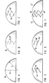
- a to F show successive process steps in the manufacture of a pair of spades.
- an approximately hemispherical spherical cap 50 made of sheet steel is assumed according to FIG.
- Such spherical caps are usually used as basket bases for reaction vessels and other containers; their manufacture is known and therefore need not be described here.
- a zigzag-shaped cutting edge 48, 48 ' is recorded, as indicated by dash-dotted lines in FIG.
- holes 54' are drilled at regular intervals on one side of the great circle 52 and holes 54 'on the other side of the great circle 52 such that each hole 54' from the two adjacent holes 54, such as can be seen from FIG. C, is equally far away and the holes 54 are at the same distance from the great circle 52 as the holes 54 '.
- each of the holes 54 is connected to one of the two adjacent holes 54 'by a cut 56, all cuts 56 being parallel to one another and preferably lying on a large circle.
- all holes 54 are connected to another of the two adjacent holes 54 'by a cut 56' in each case; these cuts 56 'are also parallel to one another and preferably lie on a large circle.
- the cuts 56 and 56 'are preferably carried out with a rotating cutting disc in order to keep the heating of the steel low.
- the cuts 56 and 56 ' give the two approximately quarter-spherical spades 44 and 44' with their cut edges 48 and 48 ', which are now sharpened on the inside of the spades 44 and 44', as is the case with a conventional hand-held grinding machine can happen.
- Spades 44 and 44 ' are preferably made of hard steel;
- a high-strength, tempered fine-grain structural steel with the DIN designation 17MnCrMo33 has proven particularly useful. Chemical composition and mechanical Properties of such a steel are known from the material sheet 210 published by Thyssen Aktiengesellschaft from June 1977.
- the steel provided there with the steel designation NA-XTRA 70 is preferably used with a minimum yield strength of 690 N / mm 2 for the spades 44 and 44 '.
- Tree transplanting implements with spades produced according to the invention are the subject of European patent 0 060 537.
Landscapes
- Life Sciences & Earth Sciences (AREA)
- Engineering & Computer Science (AREA)
- Mechanical Engineering (AREA)
- Biodiversity & Conservation Biology (AREA)
- Ecology (AREA)
- Forests & Forestry (AREA)
- Environmental Sciences (AREA)
- Transplanting Machines (AREA)
- Prostheses (AREA)
- Road Signs Or Road Markings (AREA)
Description
- Baumverpflanzungsgeräte mit sphärisch gewölbten Spaten sind seit langem bekannt; beispielsweise ist in der US-A-2 549 476 in solche Gerät dargestellt und beschrieben, bei dem zwei Spaten, die je einem Viertel einer Hohlkugel entsprechen, an je einer sie umschließenden, U-förmigen Rahmenhälfte schwenkbar gelagert sind. Die beiden Rahmenhälften lassen sich zu einem ungefähr quadratischen, in Betriebsstellung waagerechten Rahmen schließen und miteinander verriegeln. Bei geschlossenem Rahmen sind die beiden Spaten zwischen einer unteren Stellung, in der sie gemeinsam einen halbkugelförmigen Kübel bilden, und einer oberen Stellung hin- und herschwenkbar. Wenn mit diesem Gerät ein Baum ausgegraben wird, wird der Rahmen um dessen Stamm herumgelegt und geschlossen, während die Spaten nach oben geschwenkt sind. Sodann wird der Rahmen nach unten gedrückt und die Spaten werden nach unten geschwenkt, wobei ihre nach unten weisenden, etwa halbkreisförmigen Kanten in den Boden eindringen, sich dabei einander nähern und schließlich aneinander anliegen, so daß die Spaten den Wurzelballen des Baums samt umgebendem Erdreich umschließen. Nun kann durch Anheben des Gerätes der Baum samt Wurzelballen aus dem Boden herausgehoben werden.
- Über die Herstellung der Spaten ist der US-A-2549 476 nichts zu entnehmen; es war bisher üblich, solche Spaten einzeln herzustellen und ihre Grabkanten nütigenfalls mit Zähnen zu versehen, die das Eindringen in den Boden erleichtern. Diese Art der Herstellung ist umständlich und kostspielig, besonders bei großen Spaten, die zusammen einen Kübel mit einem Durchmesser von 2,50 m und mehr aufweisen können (DE-A-2 902 597).
- Der Erfindung liegt die Aufgabe zugrunde, die Herstellung sphärisch gewölbter Spaten für Baumverpflanzungsgeräts, insbesondere solche mit großem Kübeldurchmesser, zu vereinfachen.
- Die Aufgabe ist erfindungsgemäß dadurch gelöst,
- - daß eine Kugelkalotte, insbesondere aus hartem Stahlblech, geformt wird,
- - in die Kugelkalotte beiderseits eines Grokreises Löcher in gleichmäßigen Abständen gegeneinander versetzt gebohrt werden,
- - und die Löcher durch zickzackförmige, den Großkreis kreuzende Schnitte miteinander verbunden werden.
- Auf diese Weise erhält man Spaten, die in ihrem Wölbungsradius genau übereinstimmen und schon infolge ihrer Herstellung, ohne jeden zusätzlichen Arbeitsaufwand, zickzackförmige Schnittkanten aufweisen, die das Hineindrücken der Spaten in den Boden wesentlich erleichtern und, um diese Wirkung noch zu verstärken, allenfalls noch schräg geschliffen werden.
- Vorzugsweise werden die Löcher auf der einen Seite des Großkreises durch eine Serie paralleler Schnitte mit je einem Loch auf der anderen Seite des Großkreises verbunden und erst dann die erstgenannten Löcher durch eine zweite Serie paralleler Schnitte im Winkel zu den erstgenannten Schnitten mit je einem weiteren Loch auf der anderen Seite des Großkreises verbunden. Dadurch wird weitgehend vermieden, daß sich die Spaten infolge von Wärmespannungen verziehen.
- Ein Ausführungsbeispiel der Erfindung wird im folgenden anhand einer schematischen Zeichnung beschrieben.
- Fig. A bis F zeigen aufeinanderfolgende Verfahrensstufen bei der Herstellung eines Paars Spaten.
- Zum Herstellen eines Paars viertelkugelförmiger Spaten 44 und 44' wird gemäß Fig.A von einer annähernd halbkugelförmigen Kugelkalotte 50 aus Stahlblech ausgegangen. Solche Kugelkalotten werden üblicherweise als Korbböden für Reaktionsgefäße und andere Behälter verwendet; ihre Herstellung ist bekannt und braucht deshalb hier nicht beschrieben zu werden.
- Auf der Kugelkalotte 50 wird, einem Großkreis 52 folgend, eine zickzackförmige Schnittkante 48, 48' aufgezeichnet, wie in Fig.B mit strichpunktierten Linien angedeutet. An den Ecken der aufgezeichneten Schnittkante 48, 48' werden auf der einen Seite des Großkreises 52 in gleichmäßigen Abständen Löcher 54 und auf der anderen Seite des Großkreises 52 Löcher 54' derart gebohrt, daß jedes Loch 54' von den beiden benachbarten Löchern 54, wie aus Fig.C ersichtlich, gleichweit entfernt ist und die Löcher 54 vom Großkreis 52 einen ebenso großen Abstand haben wie die Löcher 54'.
- Anschließend wird gemäß Fig.D jedes der Löcher 54 mit einem der beiden benachbarten Löcher 54' durch einen Schnitt 56 verbunden, wobei sämtliche Schnitte 56 einander parallel sind und vorzugsweise auf je einem Gro.kreis liegen. Daraufhin werden gemäß Fig.E sämtliche Löcher 54 mit einem anderen der beiden benachbarten Löcher 54' durch je einen Schnitt 56' verbunden; auch diese Schnitte 56' sind parallel zueinander und liegen vorzugsweise auf je einem Großkreis. Die Schnitte 56 und 56' werden vorzugsweise, um die Erwärmung des Stahls gering zu halten, mit einer rotierenden Trennscheibe ausgeführt.
- Durch die Schnitte 56 und 56' erhält man gemäß Fig.F die beiden annähernd viertelkugelförmigen Spaten 44 und 44' mit ihren Schnittkanten 48 und 48', die nun noch an der Innenseite der Spaten 44 und 44' angeschärft werden, was mit einer üblichen Handschleifmaschine geschehen kann.
- Die Spaten 44 und 44' bestehen vorzugsweise aus hartem Stahl; besonders bewährt hat sich ein hochfester, vergüteter Feinkornbaustahl mit der DIN-Bezeichnung 17MnCrMo33. Chemische Zusammensetzung und mechanische Eigenschaften eines solchen Stahls sind bekannt aus dem von der Thyssen Aktiengesellschaft herausgegebenen Werkstoffblatt 210 vom Juni 1977. Vorzugsweise wird der dort mit der Stahlbezeichnung N-A-XTRA 70 versehene Stahl mit einer Mindeststreckgrenze von 690 N/mm2 für die Spaten 44 und 44' verwendet.
- Baumverpflanzungsgesäte mit erfindungsgemäß hergestellten Spaten sind Gegenstand des Europäischen Patents 0 060 537.
Claims (2)
Applications Claiming Priority (2)
| Application Number | Priority Date | Filing Date | Title |
|---|---|---|---|
| DE3109727 | 1981-03-13 | ||
| DE19813109727 DE3109727A1 (de) | 1981-03-13 | 1981-03-13 | Baumverpflanzungsgeraet |
Related Parent Applications (1)
| Application Number | Title | Priority Date | Filing Date |
|---|---|---|---|
| EP82102025.2 Division | 1982-03-12 |
Publications (2)
| Publication Number | Publication Date |
|---|---|
| EP0128313A1 EP0128313A1 (de) | 1984-12-19 |
| EP0128313B1 true EP0128313B1 (de) | 1986-12-17 |
Family
ID=6127188
Family Applications (2)
| Application Number | Title | Priority Date | Filing Date |
|---|---|---|---|
| EP82102025A Expired EP0060537B1 (de) | 1981-03-13 | 1982-03-12 | Baumverpflanzungsgerät |
| EP84104765A Expired EP0128313B1 (de) | 1981-03-13 | 1982-03-12 | Verfahren zum Herstellen sphärisch gewölbter Spaten für ein Baumverpflanzungsgerät |
Family Applications Before (1)
| Application Number | Title | Priority Date | Filing Date |
|---|---|---|---|
| EP82102025A Expired EP0060537B1 (de) | 1981-03-13 | 1982-03-12 | Baumverpflanzungsgerät |
Country Status (2)
| Country | Link |
|---|---|
| EP (2) | EP0060537B1 (de) |
| DE (3) | DE3109727A1 (de) |
Families Citing this family (11)
| Publication number | Priority date | Publication date | Assignee | Title |
|---|---|---|---|---|
| DE3866859D1 (de) * | 1987-11-16 | 1992-01-23 | Karl Heitzler | Einzelballen-aushebe- und reihenrodegeraet. |
| NL1002916C2 (nl) * | 1996-04-22 | 1997-10-23 | Dionisius Carolus Johannus Adr | Inrichting voor het verwijderen van een kluit omvattende boom alsmede een dergelijke werkwijze. |
| US6010294A (en) * | 1998-01-27 | 2000-01-04 | Lyddon; John | Tractor hydraulic grabbing tool |
| RU2155473C1 (ru) * | 1999-06-21 | 2000-09-10 | Марийский государственный технический университет | Рабочий орган для выкопки подроста |
| DE10001078C1 (de) | 2000-01-13 | 2001-05-17 | Dieter Opitz | Vorrichtung zum Verpflanzen von Bäumen oder Sträuchern |
| KR100439380B1 (ko) * | 2001-12-29 | 2004-07-09 | 곽양진 | 이식용 수목 절취장치 |
| RU2508626C1 (ru) * | 2012-08-01 | 2014-03-10 | Федеральное государственное бюджетное образовательное учреждение высшего профессионального образования Поволжский государственный технологический университет | Устройство для пересадки подроста |
| RU2531626C2 (ru) * | 2013-02-01 | 2014-10-27 | Федеральное государственное бюджетное образовательное учреждение высшего профессионального образования "Поволжский государственный технологический университет" | Устройство для пересадки подроста |
| DE102016225917B3 (de) * | 2016-12-21 | 2018-02-22 | Freddy Elsen | Wurzelballen-Unterschneide- und Aushebegerät |
| RU204167U1 (ru) * | 2020-12-17 | 2021-05-13 | Государственное бюджетное образовательное учреждение высшего образования Нижегородский государственный инженерно-экономический университет (НГИЭУ) | Устройство для пересадки мелколесья и садовых деревьев |
| CN118000037B (zh) * | 2024-03-18 | 2025-09-30 | 中国林业科学研究院亚热带林业研究所 | 一种龙门式油茶树种植辅助支架 |
Family Cites Families (6)
| Publication number | Priority date | Publication date | Assignee | Title |
|---|---|---|---|---|
| US2549476A (en) * | 1949-10-05 | 1951-04-17 | William B Johnson | Transplanting digger |
| US2990630A (en) * | 1959-02-18 | 1961-07-04 | Howard E Crawford | Tree moving machine |
| US3460277A (en) * | 1965-12-27 | 1969-08-12 | Russell C Grover | Transplanter |
| US3558177A (en) * | 1968-10-10 | 1971-01-26 | William C Snead | Plant digging machine |
| DE2902597A1 (de) * | 1979-01-24 | 1980-07-31 | Ehren Lorenz Von | Vorrichtung fuer das ausheben und umsetzen von holzigen pflanzen, insbesondere baeumen, aus bzw. in das erdreich |
| US4226033A (en) * | 1979-06-01 | 1980-10-07 | Vermeer Manufacturing Co. | Tree transplanting machine |
-
1981
- 1981-03-13 DE DE19813109727 patent/DE3109727A1/de not_active Ceased
-
1982
- 1982-03-12 EP EP82102025A patent/EP0060537B1/de not_active Expired
- 1982-03-12 EP EP84104765A patent/EP0128313B1/de not_active Expired
- 1982-03-12 DE DE8484104765T patent/DE3274713D1/de not_active Expired
- 1982-03-12 DE DE8282102025T patent/DE3264205D1/de not_active Expired
Also Published As
| Publication number | Publication date |
|---|---|
| EP0060537A1 (de) | 1982-09-22 |
| EP0060537B1 (de) | 1985-06-19 |
| EP0128313A1 (de) | 1984-12-19 |
| DE3274713D1 (en) | 1987-01-29 |
| DE3264205D1 (en) | 1985-07-25 |
| DE3109727A1 (de) | 1982-10-14 |
Similar Documents
| Publication | Publication Date | Title |
|---|---|---|
| DE3609251C2 (de) | ||
| EP0128313A1 (de) | Verfahren zum Herstellen sphärisch gewölbter Spaten für ein Baumverpflanzungsgerät | |
| DE2205715A1 (de) | Vorrichtung zum Pflanzen | |
| DE19604008A1 (de) | Vorrichtung zum Vorschneiden oder automatischen oder halbautomatischen Abschneiden von Reben und an Spalieren festgebundenen Bäumen oder Sträuchern | |
| DE2301103B2 (de) | Holzabschervorrichtung, Insbesondere zum Fällen von Bäumen | |
| DE10001078C1 (de) | Vorrichtung zum Verpflanzen von Bäumen oder Sträuchern | |
| EP0150731A2 (de) | Handgerät zum Auflockern von Gartenboden | |
| DE202017007049U1 (de) | Scheibenwerkzeug und landwirtschaftliches Gerät, das dieses Scheibenwerkzeug aufweist | |
| DE60012516T2 (de) | Verfahren un vorrichtung zum entwurzeln von bäumen | |
| DE4121021C2 (de) | ||
| DE2739022A1 (de) | Senkrecht-furnierschaelmaschine mit einer vorrichtung zur handhabung des stammabschnitts im verlauf seiner bearbeitung | |
| DE2652990C2 (de) | Baumfällvorrichtung mit einer ringförmigen Schneideinrichtung | |
| DE2731896C2 (de) | Rohrstück zum Be- und Entlüften des Pflanzen umgebenden Erdreichs | |
| DE202008008617U1 (de) | Auffangvorrichtung für abgespaltene Holzscheite | |
| DE1913131U (de) | Landwirtschaftliches motorgeraet mit rotierenden messern oder anderen rotierenden werkzeugen. | |
| DE334268C (de) | Spargelstechmesser | |
| EP1104982B1 (de) | Pflanzgefäss aus wirrfaservlies und verfahren zu seiner herstellung | |
| AT227992B (de) | Vorrichtung zur Bearbeitung des Bodens, insbesondere bei Weingärten, Obstgärten od. dgl. | |
| DE864534C (de) | Bohrkrone fuer Stossbohrer | |
| EP1889536A1 (de) | Pflanzgefäss | |
| DE859543C (de) | Vorrichtung zum Foerdern des Eindringens von Rillenscheiben in den Boden | |
| DE712234C (de) | Seilklemmer fuer Harpunenseile | |
| DE3008009A1 (de) | Pflanzen-ausgrabungsgeraet | |
| DE202017005721U1 (de) | Pflanzspaten | |
| AT163553B (de) | Abschluß für Konservenbüchsen und ähnliche Behälter |
Legal Events
| Date | Code | Title | Description |
|---|---|---|---|
| PUAI | Public reference made under article 153(3) epc to a published international application that has entered the european phase |
Free format text: ORIGINAL CODE: 0009012 |
|
| AC | Divisional application: reference to earlier application |
Ref document number: 60537 Country of ref document: EP |
|
| AK | Designated contracting states |
Designated state(s): AT BE CH DE FR GB IT LI LU NL SE |
|
| 17P | Request for examination filed |
Effective date: 19850618 |
|
| 17Q | First examination report despatched |
Effective date: 19860507 |
|
| ITF | It: translation for a ep patent filed | ||
| GRAA | (expected) grant |
Free format text: ORIGINAL CODE: 0009210 |
|
| AC | Divisional application: reference to earlier application |
Ref document number: 60537 Country of ref document: EP |
|
| AK | Designated contracting states |
Kind code of ref document: B1 Designated state(s): AT BE CH DE FR GB IT LI LU NL SE |
|
| REF | Corresponds to: |
Ref document number: 24262 Country of ref document: AT Date of ref document: 19870115 Kind code of ref document: T |
|
| REF | Corresponds to: |
Ref document number: 3274713 Country of ref document: DE Date of ref document: 19870129 |
|
| ET | Fr: translation filed | ||
| PG25 | Lapsed in a contracting state [announced via postgrant information from national office to epo] |
Ref country code: LU Free format text: LAPSE BECAUSE OF NON-PAYMENT OF DUE FEES Effective date: 19870331 |
|
| PLBE | No opposition filed within time limit |
Free format text: ORIGINAL CODE: 0009261 |
|
| STAA | Information on the status of an ep patent application or granted ep patent |
Free format text: STATUS: NO OPPOSITION FILED WITHIN TIME LIMIT |
|
| 26N | No opposition filed | ||
| PGFP | Annual fee paid to national office [announced via postgrant information from national office to epo] |
Ref country code: FR Payment date: 19900302 Year of fee payment: 9 |
|
| PGFP | Annual fee paid to national office [announced via postgrant information from national office to epo] |
Ref country code: LU Payment date: 19900307 Year of fee payment: 9 |
|
| PGFP | Annual fee paid to national office [announced via postgrant information from national office to epo] |
Ref country code: SE Payment date: 19900308 Year of fee payment: 9 Ref country code: CH Payment date: 19900308 Year of fee payment: 9 Ref country code: AT Payment date: 19900308 Year of fee payment: 9 |
|
| PGFP | Annual fee paid to national office [announced via postgrant information from national office to epo] |
Ref country code: BE Payment date: 19900320 Year of fee payment: 9 |
|
| ITTA | It: last paid annual fee | ||
| PGFP | Annual fee paid to national office [announced via postgrant information from national office to epo] |
Ref country code: NL Payment date: 19900331 Year of fee payment: 9 Ref country code: GB Payment date: 19900331 Year of fee payment: 9 |
|
| PGFP | Annual fee paid to national office [announced via postgrant information from national office to epo] |
Ref country code: DE Payment date: 19900427 Year of fee payment: 9 |
|
| PG25 | Lapsed in a contracting state [announced via postgrant information from national office to epo] |
Ref country code: GB Effective date: 19910312 Ref country code: AT Effective date: 19910312 |
|
| PG25 | Lapsed in a contracting state [announced via postgrant information from national office to epo] |
Ref country code: SE Effective date: 19910313 |
|
| PG25 | Lapsed in a contracting state [announced via postgrant information from national office to epo] |
Ref country code: LI Effective date: 19910331 Ref country code: CH Effective date: 19910331 Ref country code: BE Effective date: 19910331 |
|
| BERE | Be: lapsed |
Owner name: OPITZ DIETER Effective date: 19910331 |
|
| PG25 | Lapsed in a contracting state [announced via postgrant information from national office to epo] |
Ref country code: NL Effective date: 19911001 |
|
| GBPC | Gb: european patent ceased through non-payment of renewal fee | ||
| NLV4 | Nl: lapsed or anulled due to non-payment of the annual fee | ||
| PG25 | Lapsed in a contracting state [announced via postgrant information from national office to epo] |
Ref country code: FR Effective date: 19911129 |
|
| REG | Reference to a national code |
Ref country code: CH Ref legal event code: PL |
|
| PG25 | Lapsed in a contracting state [announced via postgrant information from national office to epo] |
Ref country code: DE Effective date: 19920101 |
|
| REG | Reference to a national code |
Ref country code: FR Ref legal event code: ST |
|
| EUG | Se: european patent has lapsed |
Ref document number: 84104765.7 Effective date: 19911009 |