EP0122493B1 - Dispositif pour soulever, puis basculer des récipients à ordures dans un véhicule de transport d'ordures - Google Patents
Dispositif pour soulever, puis basculer des récipients à ordures dans un véhicule de transport d'ordures Download PDFInfo
- Publication number
- EP0122493B1 EP0122493B1 EP84103023A EP84103023A EP0122493B1 EP 0122493 B1 EP0122493 B1 EP 0122493B1 EP 84103023 A EP84103023 A EP 84103023A EP 84103023 A EP84103023 A EP 84103023A EP 0122493 B1 EP0122493 B1 EP 0122493B1
- Authority
- EP
- European Patent Office
- Prior art keywords
- lever
- swing arm
- supporting
- refuse
- lifting cylinder
- Prior art date
- Legal status (The legal status is an assumption and is not a legal conclusion. Google has not performed a legal analysis and makes no representation as to the accuracy of the status listed.)
- Expired
Links
Images


Classifications
-
- B—PERFORMING OPERATIONS; TRANSPORTING
- B65—CONVEYING; PACKING; STORING; HANDLING THIN OR FILAMENTARY MATERIAL
- B65F—GATHERING OR REMOVAL OF DOMESTIC OR LIKE REFUSE
- B65F3/00—Vehicles particularly adapted for collecting refuse
- B65F3/02—Vehicles particularly adapted for collecting refuse with means for discharging refuse receptacles thereinto
- B65F3/04—Linkages, pivoted arms, or pivoted carriers for raising and subsequently tipping receptacles
- B65F3/041—Pivoted arms or pivoted carriers
- B65F3/043—Pivoted arms or pivoted carriers with additional means for keeping the receptacle substantially vertical during raising
- B65F3/045—Four-bar linkages
-
- B—PERFORMING OPERATIONS; TRANSPORTING
- B65—CONVEYING; PACKING; STORING; HANDLING THIN OR FILAMENTARY MATERIAL
- B65F—GATHERING OR REMOVAL OF DOMESTIC OR LIKE REFUSE
- B65F3/00—Vehicles particularly adapted for collecting refuse
- B65F3/02—Vehicles particularly adapted for collecting refuse with means for discharging refuse receptacles thereinto
- B65F2003/0223—Vehicles particularly adapted for collecting refuse with means for discharging refuse receptacles thereinto the discharging means comprising elements for holding the receptacle
- B65F2003/024—Means for locking the rim
Definitions
- the invention relates to a lifting and tilting device for emptying larger containers, in particular for emptying waste containers in transport vehicles, according to the preamble of claim 1.
- the lifting cylinder is articulated on a bearing which lies below the pivot bearing of the swivel arm and is arranged offset relative to the front towards the front end of the vehicle.
- the lifting cylinder is essentially parallel to the swivel arm outside the four-bar linkage.
- the lifting cylinder acts on an actuating lever which is provided on the lower link.
- the lower link and the upper link are arranged parallel to each other.
- the swivel arm and the support arm are parallel to each other.
- Garbage containers must be brought into an inclined position of approximately 45 ° for emptying.
- An initially upright garbage can must be swiveled by 135 ° relative to its vertical standing position.
- the garbage container is first raised in the vertical direction by actuating the lifting cylinder in that the swivel arm remains in its hanging position and only the two parallel upper and lower links are pivoted, which lift the carrying link together with the garbage container. Only then is the tipping process initiated, with the swivel arm being pivoted through 135 ° together with the four-bar linkage now in the stop and the waste container.
- This known construction is unfavorable in both static and kinematic terms.
- the lifting cylinder also engages the lower link between the two swivel joints.
- the lifting cylinder is articulated on a projection of the swivel arm, the articulation point being close to the swivel bearing of the swivel arm.
- a waste container attached to the supporting link is raised relative to the swivel arm.
- the swivel arm is rotated about its pivot axis by means of a separate drive, so that the waste container is brought into the prescribed tilting position.
- Such a device is relatively complex because two separate drives are required.
- it is also relatively cumbersome in terms of time, so that the delivery rate is comparatively low.
- the invention has for its object to keep the emptying process as short as possible, in order not only to increase the performance, but also to better utilize the refuse collection vehicles, and at the same time to simplify the structure of the device and make it less prone to failure.
- the construction according to the invention has considerable advantages in both static and kinematic terms.
- the piston rod of the lifting cylinder is only loaded in tension in the construction according to the invention and consequently need not be designed to be very stable.
- the stroke of the cylinder is relatively short, so that you can get by with a single-stage cylinder.
- the swivel arm only needs to be swiveled upwards by about 90 ° in order to bring the carrying handle with the waste container into the upper tilt position. Since the movement of the swivel arm accounts for the major part of the actuation time, an emptying cycle is shorter than in the known devices.
- the pivoting movement of the lower link relative to the pivot arm in the lowering direction is expediently limited by a further stop, as a result of which the lowest position of the supporting link is defined.
- the swivel arm can be designed in a straight line and thus as a very simple component.
- the pivoting movement of the swivel arm in the lowering direction can be limited by a stop, the position pointing vertically upward expediently being the lower limit position of the swivel arm.
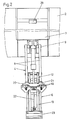
- the lifting and tilting device shown in the drawing serves for emptying waste containers 1 into a waste transport vehicle 2, of which only the rear end of the superstructure with the filling opening 3 is shown in the drawing.
- the garbage can 1 to be emptied is raised and tilted and pivoted such that, as shown in FIG. 4, it projects into the emptying opening 3 and is directed obliquely downward, so that the garbage automatically due to its gravity can slip into the garbage truck.
- the waste container 1 is placed in the opposite direction again on the floor behind the waste transport vehicle 2.
- the lifting and tilting device essentially consists of a swivel arm 4, a handlebar rectangle 5 with a supporting link 6 to which the garbage can 1 can be fastened, and a drive device in the form of a lifting cylinder 7.
- the swivel arm 4 consists of two parallel supports 8, which are pivotally attached at one end to the refuse transport vehicle 2.
- the essentially rectilinear swivel arm 4 can be swiveled upward from a vertically downward hanging position, in which the swivel arm 4 rests against a stop 10 visible in FIG. 4, into an approximately horizontal position, which corresponds to the emptying position of the waste container 1.
- the end of the swivel arm 4 facing away from the pivot bearing 9 is part of the mentioned square 5.
- This end serves as an inner link 11, to which an upper link 12 and a lower link 13 are articulated via bearings 14 and 15, respectively.
- the two links 12 and 13 are connected to the support link 6 via bearings 16 and 17, respectively.
- the support arm 6 is approximately twice as long as the inner link 11 and the lower link 13 is somewhat longer than the upper link 12.
- the handlebars 6, 12 and 13, like the swivel arm 4, are formed from two parallel supports, so that the handlebar rectangle 5 is sufficiently torsion-resistant.
- the holding device 18 consists essentially of a plurality of support supports 19 arranged side by side, which engage under the undercut edge 39 of the standardized waste container 1, and a holding plate 21 provided on a swivel plate 20 which, in the locked state, engages over the edge 19 of the waste bin 1.
- the pivot plate 20 is actuated by means of a transmission rod 22.
- a stop 23 is provided as an abutment for the lower end of the waste container 1.
- the lifting cylinder 7 provided for actuating the lifting and tilting device is likewise fastened directly to the refuse transport vehicle 2, specifically via a swivel joint 24, which is arranged at a distance from the pivot bearing 9 of the swivel arm.
- the swivel joint 24 is located somewhat above the pivot bearing 9 and is offset a little relative to the latter in the direction of the supporting link 6.
- the end of the lifting rod 25 of the lifting cylinder 7 is pivotally attached to the lower link 13.
- the lower link 13 can be pivoted back and forth between two extreme positions relative to the swivel arm 4. Its lower position is determined by a stop 26 which, as shown in dashed lines in FIG. 1, comes to rest on a contact surface 27 of the swivel arm 4. Its upward pivoting movement is limited by a stop 28 which sits on the pivot arm 4. Relative to the swivel arm 4, the lower link 13 can be swiveled by approximately 90 °.
- the lower link 13 By actuating the lifting cylinder 7, the lower link 13 is pivoted upwards with the pivot arm 4 at a standstill into the position shown in FIG. 3, in which the lower link 13 bears against the stop 28. In this position, the garbage can 1 is not only raised, but already tilted by an angle of approximately 45 °.
- the holding device 18 On the way to this position, the holding device 18 has also closed by actuating the transmission rod 22 in such a way that the holding plate 21 extends over the upper edge 39 of the waste container 1 and thus firmly secures the waste container to the device.
- the lower link 13 can no longer be pivoted relative to the swivel arm 4, so that the entire force of the lifting cylinder can now be used to rotate the swivel arm 4 about its bearing 9.
- the pivoting then takes place until the swivel arm 4 is approximately in a horizontal position corresponding to the position shown in FIG. 4, in which the waste container 1 assumes its emptying position.
- a stop pad 29 for the waste container 1 is provided at the upper edge of the filling opening 3 of the waste transport vehicle.
Claims (6)
Priority Applications (1)
| Application Number | Priority Date | Filing Date | Title |
|---|---|---|---|
| AT84103023T ATE24166T1 (de) | 1983-04-13 | 1984-03-20 | Hub- und kippvorrichtung zum entleeren von muellgefaessen in muelltransportfahrzeuge. |
Applications Claiming Priority (2)
| Application Number | Priority Date | Filing Date | Title |
|---|---|---|---|
| DE3313282A DE3313282C2 (de) | 1983-04-13 | 1983-04-13 | Hub- und Kippvorrichtung zum Entleeren von größeren Müllgefäßen |
| DE3313282 | 1983-04-13 |
Publications (2)
| Publication Number | Publication Date |
|---|---|
| EP0122493A1 EP0122493A1 (fr) | 1984-10-24 |
| EP0122493B1 true EP0122493B1 (fr) | 1986-12-10 |
Family
ID=6196218
Family Applications (1)
| Application Number | Title | Priority Date | Filing Date |
|---|---|---|---|
| EP84103023A Expired EP0122493B1 (fr) | 1983-04-13 | 1984-03-20 | Dispositif pour soulever, puis basculer des récipients à ordures dans un véhicule de transport d'ordures |
Country Status (3)
| Country | Link |
|---|---|
| EP (1) | EP0122493B1 (fr) |
| AT (1) | ATE24166T1 (fr) |
| DE (2) | DE3313282C2 (fr) |
Families Citing this family (18)
| Publication number | Priority date | Publication date | Assignee | Title |
|---|---|---|---|---|
| GB2165814B (en) * | 1984-10-20 | 1988-06-08 | Allen Jack | Refuse container lifting apparatus |
| AU608043B2 (en) * | 1987-08-18 | 1991-03-21 | Firebelt Pty Limited | Retractable arm/loader assembly |
| US4983092A (en) * | 1988-08-18 | 1991-01-08 | Jayrich Engineering Pty Ltd. | Retractable arm/loader assembly |
| DE3830227A1 (de) * | 1988-09-06 | 1990-03-15 | Zoeller Kipper | Hubkippvorrichtung zum entleeren von behaeltern in die einschuettoeffnung eines sammelbehaelters, insbesondere zum entleeren von muellbehaeltern in den sammelbehaelter eines muellfahrzeuges |
| GB2224261A (en) * | 1988-10-01 | 1990-05-02 | * Jack Allen | Tipping containers into refuse vehicles |
| ES2036914B1 (es) * | 1991-04-19 | 1994-01-01 | Ros Roca Sa | Dispositivo de elevacion para el vaciado de contenedores de basura. |
| NL1001923C2 (nl) * | 1995-12-18 | 1997-06-19 | Geesink Group B V | Inrichting voor het optillen en kantelen van een houder. |
| EP0820941A1 (fr) * | 1996-07-26 | 1998-01-28 | C.L.G.Inversiones,S.L. | Dispositif de levage et de basculement pour vider des poubelles |
| CN103129884B (zh) * | 2012-12-18 | 2014-12-31 | 华南理工大学 | 一种基于新型装载机构的环卫运输车 |
| GB201303119D0 (en) * | 2013-02-21 | 2013-04-10 | Witham Mills Engineering Ltd | A container lift and a method of emptying a container |
| CN103587727B (zh) * | 2013-10-16 | 2015-08-19 | 中国运载火箭技术研究院 | 一种自限位四连杆空间机构 |
| WO2015184634A1 (fr) * | 2014-06-06 | 2015-12-10 | Hyva Mechanics (Yangzhou) Co. Ltd. | Dispositif de levage de bac à ordures |
| NL2015999B1 (nl) * | 2015-12-21 | 2017-06-30 | Terberg Machines | Beladingssysteem voor het geleiden van een houder, voertuig voorzien daarvan, en werkwijze daarvoor. |
| CN107747616B (zh) * | 2017-11-01 | 2023-12-12 | 贵州岑祥资源科技有限责任公司 | 一种用于废旧铅酸蓄电池回收的六连杆翻转上线机构 |
| CN108328179A (zh) * | 2018-01-24 | 2018-07-27 | 陈淑芳 | 垃圾车回收装置 |
| WO2021022309A1 (fr) * | 2019-07-26 | 2021-02-04 | SCHULENBURG, Heinrich Dietrich Wilhelm | Appareil de levage |
| CN112499026A (zh) * | 2020-11-29 | 2021-03-16 | 湖南绿意华美环保科技有限公司 | 电动装卸式垃圾分类收集站 |
| CN114104564B (zh) * | 2021-12-02 | 2023-06-06 | 安徽江田环卫设备股份有限公司 | 一种自动抓取分类垃圾桶的车用机械手及其使用方法 |
Family Cites Families (6)
| Publication number | Priority date | Publication date | Assignee | Title |
|---|---|---|---|---|
| DE1201756B (de) * | 1963-09-21 | 1965-09-23 | Kloeckner Humboldt Deutz Ag | Hub- und Kippvorrichtung zum Entleeren von Muellgefaessen in Muellwagen |
| DE1266213B (de) * | 1965-05-31 | 1968-04-11 | Paul Schmedtkord | Vorrichtung zum Entleeren von Muellbehaeltern od. dgl. |
| DE2654542C3 (de) * | 1976-12-02 | 1984-03-15 | Zöller-Kipper GmbH, 6500 Mainz | Hub-Kipp-Vorrichtung für Behälter, insbesondere zum Entleeren von Müllgefäßen in Müllsammelbehälter. |
| DE2920898A1 (de) * | 1979-05-23 | 1980-12-04 | Hutsch Werner | Vorrichtung zum entleeren von behaeltern, insbesondere zum entleeren von muellgefaessen in einen muellwagen |
| DE2920900A1 (de) * | 1979-05-23 | 1980-12-04 | Theodor Stratmann | Vorrichtung zum entleeren von muellgefaessen in einen muellwagen |
| DE3123191A1 (de) * | 1980-06-11 | 1982-03-25 | Glover Webb & Liversidge Ltd., Hamble, Hampshire | Vorrichtung zum anheben und kippen von muellcontainern |
-
1983
- 1983-04-13 DE DE3313282A patent/DE3313282C2/de not_active Expired
-
1984
- 1984-03-20 EP EP84103023A patent/EP0122493B1/fr not_active Expired
- 1984-03-20 DE DE8484103023T patent/DE3461621D1/de not_active Expired
- 1984-03-20 AT AT84103023T patent/ATE24166T1/de not_active IP Right Cessation
Also Published As
| Publication number | Publication date |
|---|---|
| DE3461621D1 (en) | 1987-01-22 |
| DE3313282C2 (de) | 1985-03-07 |
| DE3313282A1 (de) | 1984-10-25 |
| ATE24166T1 (de) | 1986-12-15 |
| EP0122493A1 (fr) | 1984-10-24 |
Similar Documents
| Publication | Publication Date | Title |
|---|---|---|
| EP0122493B1 (fr) | Dispositif pour soulever, puis basculer des récipients à ordures dans un véhicule de transport d'ordures | |
| DE3830227A1 (de) | Hubkippvorrichtung zum entleeren von behaeltern in die einschuettoeffnung eines sammelbehaelters, insbesondere zum entleeren von muellbehaeltern in den sammelbehaelter eines muellfahrzeuges | |
| EP0720957A1 (fr) | Véhicule pour collecter et transporter des déchets avec un support pour le dispositif de ramassage | |
| EP0295574B1 (fr) | Véhicule de ramassage d'ordures | |
| DE2909532C2 (de) | Kippbehälter für Hublader | |
| CH667242A5 (de) | Selbstfahrendes fahrzeug mit einer kippmuldeneinrichtung. | |
| DE2909438A1 (de) | Kippvorrichtung fuer behaelter, insbesondere muellbehaelter | |
| DD296658A5 (de) | Muellsammelfahrzeug | |
| EP0106260B1 (fr) | Dispositif pour soulever et faire basculer des poubelles de grande capacité munies d'un couvercle basculant | |
| DE2741448A1 (de) | Sammelbehaelter fuer muell | |
| DE19655095C2 (de) | Müllsammelfahrzeug mit zwei um eine Querachse schwenkbar am Fahrgestell gelagerten Bügeln einer Hub-Kipp-Vorrichtung | |
| DE3809134C2 (fr) | ||
| DE4315412C2 (de) | Hub-Kippvorrichtung eines Müllsammelfahrzeuges | |
| DE3016146A1 (de) | Schuerfkuebel fuer die befestigung an einem fahrzeug | |
| DE3830989A1 (de) | Hubkippvorrichtung zum entleeren von muellbehaeltern in ein sammelfahrzeug | |
| DE1226035B (de) | Fahrzeug mit vorderseitig angeordneter Beladevorrichtung, insbesondere zum Entleeren von Muellsammelbehaeltern in den Wagenaufbau | |
| DE4334602C1 (de) | Trittbrett für ein Müllsammelfahrzeug | |
| DE2422454A1 (de) | Vorrichtung zum entleeren von grossraummuellbehaeltern an einem muellsammelwagen | |
| DE3725019C2 (fr) | ||
| DE2521209A1 (de) | Beladevorrichtung an schuettgutsammelbehaeltern, insbesondere muellsammelbehaeltern auf muellwagen | |
| DE19516133B4 (de) | Vorrichtung zum Entleeren von Müllgroßbehältern | |
| DE19919879C2 (de) | Hubkippvorrichtung | |
| EP0677458B1 (fr) | Ouvre-convercle | |
| DE3831796A1 (de) | Hub- und kippvorrichtung zum anbau an muellpressen, muellfahrzeuge u. dgl. | |
| DE1193418B (de) | Hubkippvorrichtung zum Entleeren von Muellgefaessen in staubfreie Schuettvorrichtungen an Muellsammelwagen |
Legal Events
| Date | Code | Title | Description |
|---|---|---|---|
| PUAI | Public reference made under article 153(3) epc to a published international application that has entered the european phase |
Free format text: ORIGINAL CODE: 0009012 |
|
| AK | Designated contracting states |
Designated state(s): AT BE CH DE FR GB IT LI LU NL SE |
|
| 17P | Request for examination filed |
Effective date: 19841109 |
|
| GRAA | (expected) grant |
Free format text: ORIGINAL CODE: 0009210 |
|
| AK | Designated contracting states |
Kind code of ref document: B1 Designated state(s): AT BE CH DE FR GB IT LI LU NL SE |
|
| REF | Corresponds to: |
Ref document number: 24166 Country of ref document: AT Date of ref document: 19861215 Kind code of ref document: T |
|
| PG25 | Lapsed in a contracting state [announced via postgrant information from national office to epo] |
Ref country code: SE Effective date: 19861231 |
|
| REF | Corresponds to: |
Ref document number: 3461621 Country of ref document: DE Date of ref document: 19870122 |
|
| ITF | It: translation for a ep patent filed |
Owner name: BARZANO' E ZANARDO ROMA S.P.A. |
|
| ET | Fr: translation filed | ||
| PLBE | No opposition filed within time limit |
Free format text: ORIGINAL CODE: 0009261 |
|
| STAA | Information on the status of an ep patent application or granted ep patent |
Free format text: STATUS: NO OPPOSITION FILED WITHIN TIME LIMIT |
|
| 26N | No opposition filed | ||
| ITTA | It: last paid annual fee | ||
| EPTA | Lu: last paid annual fee | ||
| PGFP | Annual fee paid to national office [announced via postgrant information from national office to epo] |
Ref country code: DE Payment date: 19960205 Year of fee payment: 13 |
|
| PGFP | Annual fee paid to national office [announced via postgrant information from national office to epo] |
Ref country code: GB Payment date: 19960305 Year of fee payment: 13 |
|
| PGFP | Annual fee paid to national office [announced via postgrant information from national office to epo] |
Ref country code: FR Payment date: 19960318 Year of fee payment: 13 |
|
| PGFP | Annual fee paid to national office [announced via postgrant information from national office to epo] |
Ref country code: BE Payment date: 19960321 Year of fee payment: 13 |
|
| PGFP | Annual fee paid to national office [announced via postgrant information from national office to epo] |
Ref country code: AT Payment date: 19960325 Year of fee payment: 13 |
|
| PGFP | Annual fee paid to national office [announced via postgrant information from national office to epo] |
Ref country code: NL Payment date: 19960328 Year of fee payment: 13 Ref country code: CH Payment date: 19960328 Year of fee payment: 13 |
|
| PGFP | Annual fee paid to national office [announced via postgrant information from national office to epo] |
Ref country code: LU Payment date: 19960501 Year of fee payment: 13 |
|
| PG25 | Lapsed in a contracting state [announced via postgrant information from national office to epo] |
Ref country code: LU Free format text: LAPSE BECAUSE OF NON-PAYMENT OF DUE FEES Effective date: 19970320 Ref country code: GB Effective date: 19970320 Ref country code: AT Effective date: 19970320 |
|
| PG25 | Lapsed in a contracting state [announced via postgrant information from national office to epo] |
Ref country code: LI Effective date: 19970331 Ref country code: CH Effective date: 19970331 Ref country code: BE Effective date: 19970331 |
|
| BERE | Be: lapsed |
Owner name: SCHMITZ KARL-HEINZ Effective date: 19970331 |
|
| PG25 | Lapsed in a contracting state [announced via postgrant information from national office to epo] |
Ref country code: NL Effective date: 19971001 |
|
| GBPC | Gb: european patent ceased through non-payment of renewal fee |
Effective date: 19970320 |
|
| REG | Reference to a national code |
Ref country code: CH Ref legal event code: PL |
|
| PG25 | Lapsed in a contracting state [announced via postgrant information from national office to epo] |
Ref country code: FR Free format text: LAPSE BECAUSE OF NON-PAYMENT OF DUE FEES Effective date: 19971128 |
|
| NLV4 | Nl: lapsed or anulled due to non-payment of the annual fee |
Effective date: 19971001 |
|
| PG25 | Lapsed in a contracting state [announced via postgrant information from national office to epo] |
Ref country code: DE Effective date: 19971202 |
|
| REG | Reference to a national code |
Ref country code: FR Ref legal event code: ST |