EP0122493B1 - Tipping apparatus for raising and subseguently emptying refuse receptacles into a refuse collecting vehicle - Google Patents
Tipping apparatus for raising and subseguently emptying refuse receptacles into a refuse collecting vehicle Download PDFInfo
- Publication number
- EP0122493B1 EP0122493B1 EP84103023A EP84103023A EP0122493B1 EP 0122493 B1 EP0122493 B1 EP 0122493B1 EP 84103023 A EP84103023 A EP 84103023A EP 84103023 A EP84103023 A EP 84103023A EP 0122493 B1 EP0122493 B1 EP 0122493B1
- Authority
- EP
- European Patent Office
- Prior art keywords
- lever
- swing arm
- supporting
- refuse
- lifting cylinder
- Prior art date
- Legal status (The legal status is an assumption and is not a legal conclusion. Google has not performed a legal analysis and makes no representation as to the accuracy of the status listed.)
- Expired
Links
Images


Classifications
-
- B—PERFORMING OPERATIONS; TRANSPORTING
- B65—CONVEYING; PACKING; STORING; HANDLING THIN OR FILAMENTARY MATERIAL
- B65F—GATHERING OR REMOVAL OF DOMESTIC OR LIKE REFUSE
- B65F3/00—Vehicles particularly adapted for collecting refuse
- B65F3/02—Vehicles particularly adapted for collecting refuse with means for discharging refuse receptacles thereinto
- B65F3/04—Linkages, pivoted arms, or pivoted carriers for raising and subsequently tipping receptacles
- B65F3/041—Pivoted arms or pivoted carriers
- B65F3/043—Pivoted arms or pivoted carriers with additional means for keeping the receptacle substantially vertical during raising
- B65F3/045—Four-bar linkages
-
- B—PERFORMING OPERATIONS; TRANSPORTING
- B65—CONVEYING; PACKING; STORING; HANDLING THIN OR FILAMENTARY MATERIAL
- B65F—GATHERING OR REMOVAL OF DOMESTIC OR LIKE REFUSE
- B65F3/00—Vehicles particularly adapted for collecting refuse
- B65F3/02—Vehicles particularly adapted for collecting refuse with means for discharging refuse receptacles thereinto
- B65F2003/0223—Vehicles particularly adapted for collecting refuse with means for discharging refuse receptacles thereinto the discharging means comprising elements for holding the receptacle
- B65F2003/024—Means for locking the rim
Definitions
- the invention relates to a lifting and tilting device for emptying larger containers, in particular for emptying waste containers in transport vehicles, according to the preamble of claim 1.
- the lifting cylinder is articulated on a bearing which lies below the pivot bearing of the swivel arm and is arranged offset relative to the front towards the front end of the vehicle.
- the lifting cylinder is essentially parallel to the swivel arm outside the four-bar linkage.
- the lifting cylinder acts on an actuating lever which is provided on the lower link.
- the lower link and the upper link are arranged parallel to each other.
- the swivel arm and the support arm are parallel to each other.
- Garbage containers must be brought into an inclined position of approximately 45 ° for emptying.
- An initially upright garbage can must be swiveled by 135 ° relative to its vertical standing position.
- the garbage container is first raised in the vertical direction by actuating the lifting cylinder in that the swivel arm remains in its hanging position and only the two parallel upper and lower links are pivoted, which lift the carrying link together with the garbage container. Only then is the tipping process initiated, with the swivel arm being pivoted through 135 ° together with the four-bar linkage now in the stop and the waste container.
- This known construction is unfavorable in both static and kinematic terms.
- the lifting cylinder also engages the lower link between the two swivel joints.
- the lifting cylinder is articulated on a projection of the swivel arm, the articulation point being close to the swivel bearing of the swivel arm.
- a waste container attached to the supporting link is raised relative to the swivel arm.
- the swivel arm is rotated about its pivot axis by means of a separate drive, so that the waste container is brought into the prescribed tilting position.
- Such a device is relatively complex because two separate drives are required.
- it is also relatively cumbersome in terms of time, so that the delivery rate is comparatively low.
- the invention has for its object to keep the emptying process as short as possible, in order not only to increase the performance, but also to better utilize the refuse collection vehicles, and at the same time to simplify the structure of the device and make it less prone to failure.
- the construction according to the invention has considerable advantages in both static and kinematic terms.
- the piston rod of the lifting cylinder is only loaded in tension in the construction according to the invention and consequently need not be designed to be very stable.
- the stroke of the cylinder is relatively short, so that you can get by with a single-stage cylinder.
- the swivel arm only needs to be swiveled upwards by about 90 ° in order to bring the carrying handle with the waste container into the upper tilt position. Since the movement of the swivel arm accounts for the major part of the actuation time, an emptying cycle is shorter than in the known devices.
- the pivoting movement of the lower link relative to the pivot arm in the lowering direction is expediently limited by a further stop, as a result of which the lowest position of the supporting link is defined.
- the swivel arm can be designed in a straight line and thus as a very simple component.
- the pivoting movement of the swivel arm in the lowering direction can be limited by a stop, the position pointing vertically upward expediently being the lower limit position of the swivel arm.
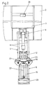
- the lifting and tilting device shown in the drawing serves for emptying waste containers 1 into a waste transport vehicle 2, of which only the rear end of the superstructure with the filling opening 3 is shown in the drawing.
- the garbage can 1 to be emptied is raised and tilted and pivoted such that, as shown in FIG. 4, it projects into the emptying opening 3 and is directed obliquely downward, so that the garbage automatically due to its gravity can slip into the garbage truck.
- the waste container 1 is placed in the opposite direction again on the floor behind the waste transport vehicle 2.
- the lifting and tilting device essentially consists of a swivel arm 4, a handlebar rectangle 5 with a supporting link 6 to which the garbage can 1 can be fastened, and a drive device in the form of a lifting cylinder 7.
- the swivel arm 4 consists of two parallel supports 8, which are pivotally attached at one end to the refuse transport vehicle 2.
- the essentially rectilinear swivel arm 4 can be swiveled upward from a vertically downward hanging position, in which the swivel arm 4 rests against a stop 10 visible in FIG. 4, into an approximately horizontal position, which corresponds to the emptying position of the waste container 1.
- the end of the swivel arm 4 facing away from the pivot bearing 9 is part of the mentioned square 5.
- This end serves as an inner link 11, to which an upper link 12 and a lower link 13 are articulated via bearings 14 and 15, respectively.
- the two links 12 and 13 are connected to the support link 6 via bearings 16 and 17, respectively.
- the support arm 6 is approximately twice as long as the inner link 11 and the lower link 13 is somewhat longer than the upper link 12.
- the handlebars 6, 12 and 13, like the swivel arm 4, are formed from two parallel supports, so that the handlebar rectangle 5 is sufficiently torsion-resistant.
- the holding device 18 consists essentially of a plurality of support supports 19 arranged side by side, which engage under the undercut edge 39 of the standardized waste container 1, and a holding plate 21 provided on a swivel plate 20 which, in the locked state, engages over the edge 19 of the waste bin 1.
- the pivot plate 20 is actuated by means of a transmission rod 22.
- a stop 23 is provided as an abutment for the lower end of the waste container 1.
- the lifting cylinder 7 provided for actuating the lifting and tilting device is likewise fastened directly to the refuse transport vehicle 2, specifically via a swivel joint 24, which is arranged at a distance from the pivot bearing 9 of the swivel arm.
- the swivel joint 24 is located somewhat above the pivot bearing 9 and is offset a little relative to the latter in the direction of the supporting link 6.
- the end of the lifting rod 25 of the lifting cylinder 7 is pivotally attached to the lower link 13.
- the lower link 13 can be pivoted back and forth between two extreme positions relative to the swivel arm 4. Its lower position is determined by a stop 26 which, as shown in dashed lines in FIG. 1, comes to rest on a contact surface 27 of the swivel arm 4. Its upward pivoting movement is limited by a stop 28 which sits on the pivot arm 4. Relative to the swivel arm 4, the lower link 13 can be swiveled by approximately 90 °.
- the lower link 13 By actuating the lifting cylinder 7, the lower link 13 is pivoted upwards with the pivot arm 4 at a standstill into the position shown in FIG. 3, in which the lower link 13 bears against the stop 28. In this position, the garbage can 1 is not only raised, but already tilted by an angle of approximately 45 °.
- the holding device 18 On the way to this position, the holding device 18 has also closed by actuating the transmission rod 22 in such a way that the holding plate 21 extends over the upper edge 39 of the waste container 1 and thus firmly secures the waste container to the device.
- the lower link 13 can no longer be pivoted relative to the swivel arm 4, so that the entire force of the lifting cylinder can now be used to rotate the swivel arm 4 about its bearing 9.
- the pivoting then takes place until the swivel arm 4 is approximately in a horizontal position corresponding to the position shown in FIG. 4, in which the waste container 1 assumes its emptying position.
- a stop pad 29 for the waste container 1 is provided at the upper edge of the filling opening 3 of the waste transport vehicle.
Abstract
Description
Die Erfindung betrifft eine Hub- und Kippvorrichtung zum Entleeren von grösseren Gefässen, insbesondere zum Entleeren von Müllgefässen in Tansportfahrzeuge, gemäss dem Oberbegriff des Anspruchs 1.The invention relates to a lifting and tilting device for emptying larger containers, in particular for emptying waste containers in transport vehicles, according to the preamble of
Bei einer bekannten Hub- und Kippvorrichtung der genannten Art (DE-A-2 654 542) ist der Hubzylinder an einem Lager angelenkt, welches unterhalb des Drehlagers des Schwenkarms liegt und relativ zu diesem nach vorn in Richtung zum Vorderende des Fahrzeugs versetzt angeordnet ist. Der Hubzylinder liegt im wesentlichen parallel zu dem Schwenkarm ausserhalb des Gelenkvierecks. Zur Kraftübertragung greift der Hubzylinder an einem Betätigungshebel an, der an dem unteren Lenker vorgesehen ist. Der untere Lenker und der obere Lenker sind relativ zueinander parallel angeordnet. In gleicher Weise liegen auch der Schwenkarm und der Traglenker parallel zueinander.In a known lifting and tilting device of the type mentioned (DE-A-2 654 542), the lifting cylinder is articulated on a bearing which lies below the pivot bearing of the swivel arm and is arranged offset relative to the front towards the front end of the vehicle. The lifting cylinder is essentially parallel to the swivel arm outside the four-bar linkage. For power transmission, the lifting cylinder acts on an actuating lever which is provided on the lower link. The lower link and the upper link are arranged parallel to each other. In the same way, the swivel arm and the support arm are parallel to each other.
Müllgefässe müssen zum Entleeren in eine Schräglage von etwa 45° gebracht werden. Eine zunächst aufrechtstehende Mülltonne muss also relativ zu ihrer vertikalen Standposition um 135° verschwenkt werden. Bei der bekannten Konstruktion wird das Müllgefäss zunächst durch Betätigung des Hubzylinders in vertikaler Richtung dadurch angehoben, dass der Schwenkarm in seiner nach unten hängenden Lage verbleibt und nur die beiden parallelen oberen und unteren Lenker verschwenkt werden, die den Traglenker zusammen mit dem Müllgefäss anheben. Erst danach wird der Kippvorgang eingeleitet, wobei der Schwenkarm zusammen mit dem nunmehr im Anschlag befindlichen Gelenkviereck und dem Müllgefäss um 135° geschwenkt wird. Diese bekannte Konstruktion ist sowohl in statischer als auch in kinematischer Hinsicht ungünstig.Garbage containers must be brought into an inclined position of approximately 45 ° for emptying. An initially upright garbage can must be swiveled by 135 ° relative to its vertical standing position. In the known construction, the garbage container is first raised in the vertical direction by actuating the lifting cylinder in that the swivel arm remains in its hanging position and only the two parallel upper and lower links are pivoted, which lift the carrying link together with the garbage container. Only then is the tipping process initiated, with the swivel arm being pivoted through 135 ° together with the four-bar linkage now in the stop and the waste container. This known construction is unfavorable in both static and kinematic terms.
Bei einer anderen bekannten Vorrichtung (DE-B-1 201 756) greift der Hubzylinder ebenfalls an dem Unterlenker zwischen den beiden Schwenkgelenken an. Der Hubzylinder ist dabei an einem Vorsprung des Schwenkarms angelenkt, wobei der Anlenkpunkt nahe dem Schwenklager des Schwenkarms liegt. Durch Betätigung des Hubzylinders wird ein an dem Traglenker befestigtes Müllgefäss relativ zum Schwenkarm angehoben. Wenn das Müllgefäss seine höchste Position erreicht hat, wird der Schwenkarm mittels eines gesonderten Antriebs um seine Schwenkachse verdreht, so dass das Müllgefäss in die vorgeschriebene Kipplage gebracht wird. Eine solche Vorrichtung ist relativ aufwendig, da zwei gesonderte Antriebe erforderlich sind. Darüber hinaus ist sie auch vom zeitlichen Ablauf her relativ schwerfällig, so dass die Förderleistung vergleichsweise gering ist.In another known device (DE-B-1 201 756) the lifting cylinder also engages the lower link between the two swivel joints. The lifting cylinder is articulated on a projection of the swivel arm, the articulation point being close to the swivel bearing of the swivel arm. By actuating the lifting cylinder, a waste container attached to the supporting link is raised relative to the swivel arm. When the waste container has reached its highest position, the swivel arm is rotated about its pivot axis by means of a separate drive, so that the waste container is brought into the prescribed tilting position. Such a device is relatively complex because two separate drives are required. In addition, it is also relatively cumbersome in terms of time, so that the delivery rate is comparatively low.
Der Erfindung liegt die Aufgabe zugrunde, den Entleerungsvorgang möglichst kurz zu halten, um nicht nur die Leistung zu erhöhen, sondern auch die Müllfahrzeuge besser auszunutzen, und gleichzeitig den Aufbau der Vorrichtung zu vereinfachen und weniger störanfällig zu gestalten.The invention has for its object to keep the emptying process as short as possible, in order not only to increase the performance, but also to better utilize the refuse collection vehicles, and at the same time to simplify the structure of the device and make it less prone to failure.
Diese Aufgabe wird mit den Merkmalen des kennzeichnenden Teils des Anspruchs 1 gelöst.This object is achieved with the features of the characterizing part of
Die erfindungsgemässe Konstruktion bringt sowohl in statischer als auch in kinematischer Hinsicht erhebliche Vorteile mit sich. Die Kolbenstange des Hubzylinders wird bei der erfindungsgemässen Konstruktion nur auf Zug belastet und braucht folglich nicht sehr stabil ausgebildet zu sein. Darüber hinaus ist der Hubweg des Zylinders relativ kurz, so dass man mit einem einstufigen Hubzylinder auskommt. Der Schwenkarm braucht nur um etwa 90° nach oben verschwenkt zu werden, um den Traglenker mit dem Müllgefäss in die obere Kippstellung zu bringen. Da die Bewegung des Schwenkarms den wesentlichen Teil der Betätigungszeit ausmacht, ist ein Entleerungszyklus kürzer als bei den bekannten Vorrichtungen.The construction according to the invention has considerable advantages in both static and kinematic terms. The piston rod of the lifting cylinder is only loaded in tension in the construction according to the invention and consequently need not be designed to be very stable. In addition, the stroke of the cylinder is relatively short, so that you can get by with a single-stage cylinder. The swivel arm only needs to be swiveled upwards by about 90 ° in order to bring the carrying handle with the waste container into the upper tilt position. Since the movement of the swivel arm accounts for the major part of the actuation time, an emptying cycle is shorter than in the known devices.
Zweckmässig ist die Schwenkbewegung des Unterlenkers relativ zum Schwenkarm in Absenkrichtung durch einen weiteren Anschlag begrenzt, wodurch die tiefste Position des Traglenkers definiert wird.The pivoting movement of the lower link relative to the pivot arm in the lowering direction is expediently limited by a further stop, as a result of which the lowest position of the supporting link is defined.
Der Schwenkarm kann bei der erfindungsgemässen Konstruktion geradlinig und somit als sehr einfaches Bauteil ausgebildet sein.In the construction according to the invention, the swivel arm can be designed in a straight line and thus as a very simple component.
Die Schwenkbewegung des Schwenkarms in Absenkrichtung kann durch einen Anschlag begrenzt sein, wobei zweckmässig die senkrecht nach oben weisende Stellung die untere Grenzstellung des Schwenkarms sein sollte.The pivoting movement of the swivel arm in the lowering direction can be limited by a stop, the position pointing vertically upward expediently being the lower limit position of the swivel arm.
Die Erfindung ist in der Zeichnung beispielsweise veranschaulicht und im nachstehenden im einzelnen anhand der Zeichnung beschrieben. Es zeigen:
- Fig. 1 eine Seitenansicht der Hub-und Kippvorrichtung in ihrer untersten Position;
- Fig. 2 eine Ansicht der Vorrichtung in Richtung des
Pfeiles 11 aus Fig. 1; - Fig. 3 die gleiche Seitenansicht wie Fig. 1 in einer teilweise angehobenen und geschwenkten Position und
- Fig. 4 eine entsprechende Ansicht wie in Fig. 1 und 3, bei der die Vorrichtung in ihrer Entleerungsstellung steht.
- Figure 1 is a side view of the lifting and tilting device in its lowest position.
- FIG. 2 shows a view of the device in the direction of
arrow 11 from FIG. 1; - Fig. 3 shows the same side view as Fig. 1 in a partially raised and pivoted position and
- Fig. 4 is a view similar to that in Figs. 1 and 3, in which the device is in its emptying position.
Die in der Zeichnung dargestellte Hub- und Kippvorrichtung dient zum Entleeren von Müllgefässen 1 in ein Mülltransportfahrzeug 2, von dem in der Zeichnung lediglich das hintere Ende der Aufbauten mit der Einfüllöffnung 3 dargestellt ist. Mit der in der Zeichnung dargestellten Vorrichtung wird die zu entleerende Mülltonne 1 angehoben und derart gekippt und verschwenkt, dass sie, wie in Fig. 4 dargestellt, in die Entleerungsöffnung 3 hineinragt und schräg nach unten gerichtet ist, so dass der Müll aufgrund seiner Schwerkraft selbsttätig in das Mülltransportfahrzeug hineinrutschen kann. Danach wird das Müllgefäss 1 in umgekehrter Richtung wieder auf dem Boden hinter dem Mülltransportfahrzeug 2 abgestellt.The lifting and tilting device shown in the drawing serves for emptying
Die Hub- und Kippvorrichtung besteht im wesentlichen aus einem Schwenkarm 4, einem Lenkerviereck 5 mit einem Traglenker 6, an welchem die Mülltonne 1 befestigbar ist, sowie einer Antriebseinrichtung in Form eines Hubzylinders 7.The lifting and tilting device essentially consists of a
Der Schwenkarm 4 besteht aus zwei parallelen Trägern 8, die mit ihrem einen Ende schwenkbar an dem Mülltransportfahrzeug 2 befestigt sind. Als Schwenklager dient ein fest mit dem Mülltransportfahrzeug verbundener Zapfen 9, der in horizontaler Lage quer zur Längsachse des Fahrzeugs angeordnet und fest mit diesem verbunden ist. Der im wesentlichen geradlinig ausgebildete Schwenkarm 4 ist aus einer senkrecht nach unten hängenden Stellung, in der der Schwenkarm 4 an einem in Fig. 4 sichtbaren Anschlag 10 anliegt, nach oben in eine etwa horizontale Stellung schwenkbar, die der Entleerungsstellung des Müllgefässes 1 entspricht.The
Das dem Drehlager 9 abgewandte Ende des Schwenkarms 4 ist Teil des erwähnten Lenkervierecks 5. Dieses Ende dient als Innenlenker 11, an welchem ein Oberlenker 12 und ein Unterlenker 13 über Lager 14 bzw. 15 angelenkt sind. Die beiden Lenker 12 und 13 sind über Lager 16 bzw. 17 mit dem Traglenker 6 verbunden. Der Traglenker 6 ist etwa doppelt so lang wie der Innenlenker 11 und der Unterlenker 13 ist etwas länger als der Oberlenker 12.The end of the
Die Lenker 6, 12 und 13 sind ebenso wie der Schwenkarm 4 aus zwei parallelen Trägern gebildet, so dass das Lenkerviereck 5 ausreichend verwindungsstabil ist.The
Der Traglenker 6, der in seiner untersten Position etwa vertikal angeordnet ist, ist an seinem oberen Ende mit einer Halteeinrichtung 18 für eine Mülltonne 1 versehen. Die Halteeinrichtung 18 besteht im wesentlichen aus mehreren nebeneinander angeordneten Stützauflagern 19, die unter den hinterschnittenen Rand 39 des genormten Müllgefässes 1 greifen, sowie einem an einer Schwenkplatte 20 vorgesehenen Halteblech 21, welches im verriegelten Zustand über den Rand 19 der Mülltonne 1 greift. Die Schwenkplatte 20 wird mit Hilfe einer Übertragungsstange 22 betätigt.The
Am unteren Ende des Tragarms 6 ist ein Anschlag 23 als Widerlager für das untere Ende des Müllgefässes 1 vorgesehen.At the lower end of the
Der zur Betätigung der Hub- und Kippvorrichtung vorgesehene Hubzylinder 7 ist ebenfalls unmittelbar an dem Mülltransportfahrzeug 2 befestigt, und zwar über ein Schwenkgelenk 24, welches in einem Abstand von dem Drehlager 9 des Schwenkarms angeordnet ist. Das Schwenkgelenk 24 liegt etwas oberhalb des Drehlagers 9 und ist relativ zu diesem ein Stück nach hinten in Richtung zum Traglenker 6 versetzt angeordnet. Die Hubstange 25 des Hubzylinders 7 ist mit ihrem Ende schwenkbar an dem Unterlenker 13 befestigt.The lifting
Der Unterlenker 13 ist relativ zu dem Schwenkarm 4 zwischen zwei Extremstellungen hin- und herverschwenkbar. Seine untere Stellung wird durch einen Anschlag 26 bestimmt, der, wie in Fig. 1 gestrichelt dargestellt, an einer Anlagefläche 27 des Schwenkarms 4 zur Anlage kommt. Seine nach oben gerichtete Schwenkbewegung ist durch einen Anschlag 28 begrenzt, der an dem Schwenkarm 4 sitzt. Relativ zu dem Schwenkarm 4 ist der Unterlenker 13 etwa um 90° schwenkbar.The
Die Hub- und Kippvorrichtung funktioniert wie folgt:
- Die Vorrichtung wird zunächst in ihre Aufnahmestellung gebracht, in der der
Schwenkarm 4 senkrecht nach unten weist und derHubzylinder 7 voll ausgefahren ist, so dass derUnterlenker 13 seine tiefste Stellung einnimmt, in welcher derAnschlag 26 an derAnlagefläche 27 anliegt. In dieser Stellung befinden sich die Oberkanten derStützauflager 19 tiefer als derobere Rand 39 einesgenormten Müllgefässes 1. Dann wird einMüllgefäss 1 an denTraglenker 6 derart herangeführt, dass dieStützauflager 19 sich unmittelbar unterhalb desRandes 39 desMüllgefässes 1 befinden.
- The device is first brought into its receiving position, in which the
swivel arm 4 points vertically downward and the liftingcylinder 7 is fully extended, so that thelower link 13 assumes its lowest position, in which thestop 26 rests on thecontact surface 27. In this position, the upper edges of the support supports 19 are lower than theupper edge 39 of astandardized waste container 1. Then awaste container 1 is brought up to the supportinglink 6 in such a way that the support supports 19 are located directly below theedge 39 of thewaste container 1.
Durch Betätigung des Hubzylinders 7 wird der Unterlenker 13 bei stillstehendem Schwenkarm 4 nach oben in die in Fig. 3 dargestellte Position geschwenkt, in welcher der Unterlenker 13 an dem Anschlag 28 anliegt. In dieser Position ist die Mülltonne 1 nicht nur angehoben, sondern bereits um einen Winkel von etwa 45° gekippt. Auf dem Weg in diese Position hat sich durch Betätigung der Übertragungsstange 22 auch die Halteeinrichtung 18 derart geschlossen, dass das Halteblech 21 über den oberen Rand 39 des Müllgefässes 1 greift und das Müllgefäss somit fest an der Vorrichtung sichert.By actuating the
Wenn in dieser Position der Hubzylinder 7 weiter betätigt wird, so kann der Unterlenker 13 gegenüber dem Schwenkarm 4 nicht mehr verschwenkt werden, so dass nunmehr die gesamte Kraft des Hubzylinders zur Drehung des Schwenkarms 4 um sein Lager 9 ausgenutzt werden kann. Die Schwenkung erfolgt dann so weit, bis der Schwenkarm 4 entsprechend der in Fig. 4 dargestellten Position etwa in horizontaler Lage steht, in welcher das Müllgefäss 1 seine Entleerungsposition einnimmt. Um ein Überschlagen des Müllgefässes 1 zu verhindern, ist am oberen Rand der Einfüllöffnung 3 des Mülltransportfahrzeugs ein Anschlagpolster 29 für das Müllgefäss 1 vorgesehen. Wenn das Müllgefäss 1 entleert ist, wird die Kolbenstange 25 wieder aus dem Hubzylinder 7 ausgefahren, so dass die Bewegung nunmehr wieder in umgekehrter Richtung erfolgt, und zwar so weit, bis der Schwenkarm 4 in seiner senkrecht nach unten weisenden Stellung an dem Anschlag 4 anliegt und der Unterlenker 13 seine tiefste Stellung einnimmt, in der sein Anschlag 26 an der Anlagefläche 27 anliegt. In dieser abgesenkten Position hat sich auch die Halteeinrichtung 18 bereits wieder geöffnet und die Stützauflager 19 befinden sich in einem geringen Abstand unterhalb des oberen Randes 39 des Müllgefässes 1, so dass das Müllgefäss völlig frei auf dem Boden steht und weggefahren werden kann.If the
Claims (6)
Priority Applications (1)
| Application Number | Priority Date | Filing Date | Title |
|---|---|---|---|
| AT84103023T ATE24166T1 (en) | 1983-04-13 | 1984-03-20 | LIFTING AND TILT DEVICE FOR EMPTYING WASTE CONTAINERS IN WASTE TRANSPORT VEHICLES. |
Applications Claiming Priority (2)
| Application Number | Priority Date | Filing Date | Title |
|---|---|---|---|
| DE3313282 | 1983-04-13 | ||
| DE3313282A DE3313282C2 (en) | 1983-04-13 | 1983-04-13 | Lifting and tilting device for emptying larger garbage containers |
Publications (2)
| Publication Number | Publication Date |
|---|---|
| EP0122493A1 EP0122493A1 (en) | 1984-10-24 |
| EP0122493B1 true EP0122493B1 (en) | 1986-12-10 |
Family
ID=6196218
Family Applications (1)
| Application Number | Title | Priority Date | Filing Date |
|---|---|---|---|
| EP84103023A Expired EP0122493B1 (en) | 1983-04-13 | 1984-03-20 | Tipping apparatus for raising and subseguently emptying refuse receptacles into a refuse collecting vehicle |
Country Status (3)
| Country | Link |
|---|---|
| EP (1) | EP0122493B1 (en) |
| AT (1) | ATE24166T1 (en) |
| DE (2) | DE3313282C2 (en) |
Families Citing this family (18)
| Publication number | Priority date | Publication date | Assignee | Title |
|---|---|---|---|---|
| GB2165814B (en) * | 1984-10-20 | 1988-06-08 | Allen Jack | Refuse container lifting apparatus |
| AU608043B2 (en) * | 1987-08-18 | 1991-03-21 | Firebelt Pty Limited | Retractable arm/loader assembly |
| US4983092A (en) * | 1988-08-18 | 1991-01-08 | Jayrich Engineering Pty Ltd. | Retractable arm/loader assembly |
| DE3830227A1 (en) * | 1988-09-06 | 1990-03-15 | Zoeller Kipper | LIFTING AND TILTING DEVICE FOR EMPTYING CONTAINERS IN THE BOTTOM OPENING OF A COLLECTOR, ESPECIALLY FOR EMPTYING WASTE CONTAINERS IN THE COLLECTOR OF A WASTE VEHICLE |
| GB2224261A (en) * | 1988-10-01 | 1990-05-02 | * Jack Allen | Tipping containers into refuse vehicles |
| ES2036914B1 (en) * | 1991-04-19 | 1994-01-01 | Ros Roca Sa | LIFTING DEVICE FOR EMPTYING GARBAGE CONTAINERS. |
| NL1001923C2 (en) * | 1995-12-18 | 1997-06-19 | Geesink Group B V | Arrangement for lifting and tipping over containers |
| EP0820941A1 (en) * | 1996-07-26 | 1998-01-28 | C.L.G.Inversiones,S.L. | Lifting and tipping device for emptying refuse receptacles |
| CN103129884B (en) * | 2012-12-18 | 2014-12-31 | 华南理工大学 | Environmental sanitation transport car based on novel loading mechanism |
| GB201303119D0 (en) * | 2013-02-21 | 2013-04-10 | Witham Mills Engineering Ltd | A container lift and a method of emptying a container |
| CN103587727B (en) * | 2013-10-16 | 2015-08-19 | 中国运载火箭技术研究院 | A kind of from spacing double leval jib space mechanism |
| WO2015184634A1 (en) * | 2014-06-06 | 2015-12-10 | Hyva Mechanics (Yangzhou) Co. Ltd. | Garbage bin lifter |
| NL2015999B1 (en) * | 2015-12-21 | 2017-06-30 | Terberg Machines | Loading system for guiding a container, vehicle provided with it, and method thereof. |
| CN107747616B (en) * | 2017-11-01 | 2023-12-12 | 贵州岑祥资源科技有限责任公司 | Six-connecting-rod overturning and wire feeding mechanism for recycling waste lead-acid storage batteries |
| CN108328179A (en) * | 2018-01-24 | 2018-07-27 | 陈淑芳 | Garbage truck retracting device |
| WO2021022309A1 (en) * | 2019-07-26 | 2021-02-04 | SCHULENBURG, Heinrich Dietrich Wilhelm | A lifting apparatus |
| CN112499026A (en) * | 2020-11-29 | 2021-03-16 | 湖南绿意华美环保科技有限公司 | Electric loading and unloading type garbage classification and collection station |
| CN114104564B (en) * | 2021-12-02 | 2023-06-06 | 安徽江田环卫设备股份有限公司 | Automatic grabbing and sorting garbage can vehicle manipulator and application method thereof |
Family Cites Families (6)
| Publication number | Priority date | Publication date | Assignee | Title |
|---|---|---|---|---|
| DE1201756B (en) * | 1963-09-21 | 1965-09-23 | Kloeckner Humboldt Deutz Ag | Lifting and tilting device for emptying garbage cans in garbage trucks |
| DE1266213B (en) * | 1965-05-31 | 1968-04-11 | Paul Schmedtkord | Device for emptying garbage containers or the like. |
| DE2654542C3 (en) * | 1976-12-02 | 1984-03-15 | Zöller-Kipper GmbH, 6500 Mainz | Lift and tilt device for containers, in particular for emptying refuse containers into refuse collection containers. |
| DE2920900A1 (en) * | 1979-05-23 | 1980-12-04 | Theodor Stratmann | Vehicle-mounted dustbin emptying mechanism - has guide link coupled to actuator and sliding in arm on collector vehicle |
| DE2920898A1 (en) * | 1979-05-23 | 1980-12-04 | Hutsch Werner | Collector vehicle rubbish skip emptying mechanism - has single guide link between arm and skip support to provide arc of movement |
| DE3123191A1 (en) * | 1980-06-11 | 1982-03-25 | Glover Webb & Liversidge Ltd., Hamble, Hampshire | Apparatus for raising and tipping refuse containers |
-
1983
- 1983-04-13 DE DE3313282A patent/DE3313282C2/en not_active Expired
-
1984
- 1984-03-20 EP EP84103023A patent/EP0122493B1/en not_active Expired
- 1984-03-20 DE DE8484103023T patent/DE3461621D1/en not_active Expired
- 1984-03-20 AT AT84103023T patent/ATE24166T1/en not_active IP Right Cessation
Also Published As
| Publication number | Publication date |
|---|---|
| EP0122493A1 (en) | 1984-10-24 |
| DE3313282A1 (en) | 1984-10-25 |
| DE3461621D1 (en) | 1987-01-22 |
| DE3313282C2 (en) | 1985-03-07 |
| ATE24166T1 (en) | 1986-12-15 |
Similar Documents
| Publication | Publication Date | Title |
|---|---|---|
| EP0122493B1 (en) | Tipping apparatus for raising and subseguently emptying refuse receptacles into a refuse collecting vehicle | |
| DE3830227A1 (en) | LIFTING AND TILTING DEVICE FOR EMPTYING CONTAINERS IN THE BOTTOM OPENING OF A COLLECTOR, ESPECIALLY FOR EMPTYING WASTE CONTAINERS IN THE COLLECTOR OF A WASTE VEHICLE | |
| EP0720957A1 (en) | Vehicle for collecting and transporting refuse with a support for the pick-up device | |
| DE4005968C2 (en) | Garbage collection vehicle | |
| DE2909532C2 (en) | Tipping container for lifters | |
| DE3432619C2 (en) | ||
| EP0295574A2 (en) | Refuse collection vehicle | |
| DE2909438A1 (en) | Automatic dustbin tipping mechanism - has lifting arms engaging behind centre of gravity and tipping edge support | |
| DD296658A5 (en) | MUELLSAMMELFAHRZEUG | |
| EP0106260B1 (en) | Lifting and tipping mechanism for large refuse bins provided with a hinged lid | |
| DE2741448A1 (en) | Refuse loader for lorry - has swinging arms to invert container above load bed including sliding cover opening mechanism | |
| DE19655095C2 (en) | Lifting and tipping device with two pivotable stirrups for refuse collecting vehicle | |
| DE3809134C2 (en) | ||
| DE4315412C2 (en) | Lifting and tipping device of a refuse collection vehicle | |
| DE3016146A1 (en) | SCHUERFKÜBEL FOR FASTENING ON A VEHICLE | |
| DE3830989A1 (en) | LIFTING AND TILTING DEVICE FOR EMPTYING WASTE CONTAINERS IN A COLLECTING VEHICLE | |
| DE1226035B (en) | Vehicle with loading device arranged on the front, in particular for emptying refuse containers into the vehicle body | |
| DE4334602C1 (en) | Platform for a refuse collection vehicle | |
| DE2422454A1 (en) | DEVICE FOR EMPTYING LARGE WASTE BIN ON A WASTE COLLECTOR | |
| DE3725019C2 (en) | ||
| DE2521209A1 (en) | Bulk material container loader - couples and manipulates full skips for discharge into transport container | |
| DE19516133B4 (en) | Device for emptying large refuse containers | |
| DE19919879C2 (en) | tipper unit | |
| EP0677458B1 (en) | Lid opener | |
| DE3831796A1 (en) | LIFTING AND TILTING DEVICE FOR MOUNTING ON MUEL PRESSES, MUELL VEHICLES AND THE LIKE. |
Legal Events
| Date | Code | Title | Description |
|---|---|---|---|
| PUAI | Public reference made under article 153(3) epc to a published international application that has entered the european phase |
Free format text: ORIGINAL CODE: 0009012 |
|
| AK | Designated contracting states |
Designated state(s): AT BE CH DE FR GB IT LI LU NL SE |
|
| 17P | Request for examination filed |
Effective date: 19841109 |
|
| GRAA | (expected) grant |
Free format text: ORIGINAL CODE: 0009210 |
|
| AK | Designated contracting states |
Kind code of ref document: B1 Designated state(s): AT BE CH DE FR GB IT LI LU NL SE |
|
| REF | Corresponds to: |
Ref document number: 24166 Country of ref document: AT Date of ref document: 19861215 Kind code of ref document: T |
|
| PG25 | Lapsed in a contracting state [announced via postgrant information from national office to epo] |
Ref country code: SE Effective date: 19861231 |
|
| REF | Corresponds to: |
Ref document number: 3461621 Country of ref document: DE Date of ref document: 19870122 |
|
| ITF | It: translation for a ep patent filed |
Owner name: BARZANO' E ZANARDO ROMA S.P.A. |
|
| ET | Fr: translation filed | ||
| PLBE | No opposition filed within time limit |
Free format text: ORIGINAL CODE: 0009261 |
|
| STAA | Information on the status of an ep patent application or granted ep patent |
Free format text: STATUS: NO OPPOSITION FILED WITHIN TIME LIMIT |
|
| 26N | No opposition filed | ||
| ITTA | It: last paid annual fee | ||
| EPTA | Lu: last paid annual fee | ||
| PGFP | Annual fee paid to national office [announced via postgrant information from national office to epo] |
Ref country code: DE Payment date: 19960205 Year of fee payment: 13 |
|
| PGFP | Annual fee paid to national office [announced via postgrant information from national office to epo] |
Ref country code: GB Payment date: 19960305 Year of fee payment: 13 |
|
| PGFP | Annual fee paid to national office [announced via postgrant information from national office to epo] |
Ref country code: FR Payment date: 19960318 Year of fee payment: 13 |
|
| PGFP | Annual fee paid to national office [announced via postgrant information from national office to epo] |
Ref country code: BE Payment date: 19960321 Year of fee payment: 13 |
|
| PGFP | Annual fee paid to national office [announced via postgrant information from national office to epo] |
Ref country code: AT Payment date: 19960325 Year of fee payment: 13 |
|
| PGFP | Annual fee paid to national office [announced via postgrant information from national office to epo] |
Ref country code: NL Payment date: 19960328 Year of fee payment: 13 Ref country code: CH Payment date: 19960328 Year of fee payment: 13 |
|
| PGFP | Annual fee paid to national office [announced via postgrant information from national office to epo] |
Ref country code: LU Payment date: 19960501 Year of fee payment: 13 |
|
| PG25 | Lapsed in a contracting state [announced via postgrant information from national office to epo] |
Ref country code: LU Free format text: LAPSE BECAUSE OF NON-PAYMENT OF DUE FEES Effective date: 19970320 Ref country code: GB Effective date: 19970320 Ref country code: AT Effective date: 19970320 |
|
| PG25 | Lapsed in a contracting state [announced via postgrant information from national office to epo] |
Ref country code: LI Effective date: 19970331 Ref country code: CH Effective date: 19970331 Ref country code: BE Effective date: 19970331 |
|
| BERE | Be: lapsed |
Owner name: SCHMITZ KARL-HEINZ Effective date: 19970331 |
|
| PG25 | Lapsed in a contracting state [announced via postgrant information from national office to epo] |
Ref country code: NL Effective date: 19971001 |
|
| GBPC | Gb: european patent ceased through non-payment of renewal fee |
Effective date: 19970320 |
|
| REG | Reference to a national code |
Ref country code: CH Ref legal event code: PL |
|
| PG25 | Lapsed in a contracting state [announced via postgrant information from national office to epo] |
Ref country code: FR Free format text: LAPSE BECAUSE OF NON-PAYMENT OF DUE FEES Effective date: 19971128 |
|
| NLV4 | Nl: lapsed or anulled due to non-payment of the annual fee |
Effective date: 19971001 |
|
| PG25 | Lapsed in a contracting state [announced via postgrant information from national office to epo] |
Ref country code: DE Effective date: 19971202 |
|
| REG | Reference to a national code |
Ref country code: FR Ref legal event code: ST |