EP0116829B1 - Druckbehälter zur Aufnahme von Flüssigkeiten - Google Patents
Druckbehälter zur Aufnahme von Flüssigkeiten Download PDFInfo
- Publication number
- EP0116829B1 EP0116829B1 EP84100184A EP84100184A EP0116829B1 EP 0116829 B1 EP0116829 B1 EP 0116829B1 EP 84100184 A EP84100184 A EP 84100184A EP 84100184 A EP84100184 A EP 84100184A EP 0116829 B1 EP0116829 B1 EP 0116829B1
- Authority
- EP
- European Patent Office
- Prior art keywords
- cover
- pressure vessel
- wall
- vessel
- order
- Prior art date
- Legal status (The legal status is an assumption and is not a legal conclusion. Google has not performed a legal analysis and makes no representation as to the accuracy of the status listed.)
- Expired
Links
- 239000007788 liquid Substances 0.000 title claims description 9
- 239000003973 paint Substances 0.000 claims description 9
- 238000010276 construction Methods 0.000 description 1
- 239000012530 fluid Substances 0.000 description 1
Images

Classifications
-
- B—PERFORMING OPERATIONS; TRANSPORTING
- B05—SPRAYING OR ATOMISING IN GENERAL; APPLYING FLUENT MATERIALS TO SURFACES, IN GENERAL
- B05C—APPARATUS FOR APPLYING FLUENT MATERIALS TO SURFACES, IN GENERAL
- B05C17/00—Hand tools or apparatus using hand held tools, for applying liquids or other fluent materials to, for spreading applied liquids or other fluent materials on, or for partially removing applied liquids or other fluent materials from, surfaces
- B05C17/02—Rollers ; Hand tools comprising coating rollers or coating endless belts
- B05C17/03—Rollers ; Hand tools comprising coating rollers or coating endless belts with feed system for supplying material from an external source or with a reservoir or container for liquid or other fluent material located in or on the hand tool outside the coating roller
- B05C17/0316—Rollers ; Hand tools comprising coating rollers or coating endless belts with feed system for supplying material from an external source or with a reservoir or container for liquid or other fluent material located in or on the hand tool outside the coating roller with pressurised or compressible container
-
- F—MECHANICAL ENGINEERING; LIGHTING; HEATING; WEAPONS; BLASTING
- F16—ENGINEERING ELEMENTS AND UNITS; GENERAL MEASURES FOR PRODUCING AND MAINTAINING EFFECTIVE FUNCTIONING OF MACHINES OR INSTALLATIONS; THERMAL INSULATION IN GENERAL
- F16J—PISTONS; CYLINDERS; SEALINGS
- F16J13/00—Covers or similar closure members for pressure vessels in general
- F16J13/02—Detachable closure members; Means for tightening closures
- F16J13/12—Detachable closure members; Means for tightening closures attached by wedging action by means of screw-thread, interrupted screw-thread, bayonet closure, or the like
-
- B—PERFORMING OPERATIONS; TRANSPORTING
- B05—SPRAYING OR ATOMISING IN GENERAL; APPLYING FLUENT MATERIALS TO SURFACES, IN GENERAL
- B05C—APPARATUS FOR APPLYING FLUENT MATERIALS TO SURFACES, IN GENERAL
- B05C21/00—Accessories or implements for use in connection with applying liquids or other fluent materials to surfaces, not provided for in groups B05C1/00 - B05C19/00
-
- F—MECHANICAL ENGINEERING; LIGHTING; HEATING; WEAPONS; BLASTING
- F16—ENGINEERING ELEMENTS AND UNITS; GENERAL MEASURES FOR PRODUCING AND MAINTAINING EFFECTIVE FUNCTIONING OF MACHINES OR INSTALLATIONS; THERMAL INSULATION IN GENERAL
- F16J—PISTONS; CYLINDERS; SEALINGS
- F16J13/00—Covers or similar closure members for pressure vessels in general
- F16J13/24—Covers or similar closure members for pressure vessels in general with safety devices, e.g. to prevent opening prior to pressure release
-
- B—PERFORMING OPERATIONS; TRANSPORTING
- B05—SPRAYING OR ATOMISING IN GENERAL; APPLYING FLUENT MATERIALS TO SURFACES, IN GENERAL
- B05C—APPARATUS FOR APPLYING FLUENT MATERIALS TO SURFACES, IN GENERAL
- B05C17/00—Hand tools or apparatus using hand held tools, for applying liquids or other fluent materials to, for spreading applied liquids or other fluent materials on, or for partially removing applied liquids or other fluent materials from, surfaces
- B05C17/02—Rollers ; Hand tools comprising coating rollers or coating endless belts
- B05C17/03—Rollers ; Hand tools comprising coating rollers or coating endless belts with feed system for supplying material from an external source or with a reservoir or container for liquid or other fluent material located in or on the hand tool outside the coating roller
- B05C17/0308—Rollers ; Hand tools comprising coating rollers or coating endless belts with feed system for supplying material from an external source or with a reservoir or container for liquid or other fluent material located in or on the hand tool outside the coating roller the liquid being supplied to the inside of the coating roller
Definitions
- the invention relates to a pressure container for holding liquids, in particular for the continuous feeding of a paint roller connected to it via a hose line, a filling brush, a nozzle or the like.
- a pressure container for holding liquids, in particular for the continuous feeding of a paint roller connected to it via a hose line, a filling brush, a nozzle or the like.
- the filling opening of the pressure container being gas by a removable cover - And is sealed liquid-tight, which is held by means of a bayonet lock.
- the lid which is U-shaped in cross section, is screwed on by means of a thread machined into the outer surface of the vessel.
- a seal is clamped between these two parts, there is often no secure holding of the cover and a pressure-tight seal.
- the screw connection can sometimes not be tightened enough, it can also loosen itself due to vibrations, so that pressure is released in the pressure vessel and proper operation is therefore no longer possible.
- the refilling of a pressure vessel designed in this way is very time-consuming and cumbersome, since tools are usually connected to the lid and must therefore be removed or rotated together with the lid several times when unscrewing and screwing it on again.
- the object of the invention is therefore to provide a pressure vessel for holding liquids of the aforementioned type, in which the lid is not only easily and quickly removed and replaced, but is held reliably in the closed position, so that an automatic unwanted opening is definitely excluded.
- the handling when removing the cover and re-tensioning should therefore be safe and easy, and the construction effort to achieve this should be kept low.
- a pressure vessel of the aforementioned type in that the bayonet catch is made by means of two or more incisions incorporated into the vessel lid, preferably arranged uniformly distributed over the circumference and extending in the circumferential direction, and associated therewith on the vessel wall in the upper region thereof built-in projections is formed, which can be inserted into the incisions by turning, and that a pressure release valve which can be unlocked by hand and whose adjustable valve body can be latched to the container wall is inserted into the container in order to secure it against excess pressure and to lock the container lid in the closed position.
- valve body of the pressure relief valve with a centrally arranged peg-shaped extension which is machined into a preferably semicircular, inwardly open recess in the end of the container wall facing the container lid can be introduced.
- the spring-loaded pressure relief valve should in this case be inserted in a vented receiving chamber formed in the container lid, on the end wall of which the valve spring is supported, so that it is protected against damage.
- the pressure vessel is thus vented before the lid can be removed and the locking mechanism is released when the lid is turned, so that the lid can be removed and replaced without difficulty.
- the container lid can be equipped with a collar, preferably arranged in the center, for holding and fastening an intake hose that can be inserted into the pressure container and the hose line leading to the paint roller.
- the design provided according to the invention makes it possible with simple means to attach and detach the lid of a pressure vessel easily and without difficulty, moreover it is excluded with certainty that the container lid can detach itself and that when the container lid is removed, pressure medium is still present the container. If the lid is attached to the pressure vessel by means of a specially designed bayonet lock and the vessel lid is locked in the closed position with the help of the pressure relief valve necessary for pressure limitation, this ensures that the vessel lid is locked exactly. Damage to the seal is therefore excluded, and the connection, depending on the division of the projections engaging in the cutouts, is only slight To produce a rotation of, for example, 90 °.
- the pressure relief valve in order to be able to remove the cover, the pressure relief valve must first be unlocked so that the pressure vessel is vented before the cover can be removed. The replacement of a paint container must therefore be carried out in a short time, and the risk of an accident is avoided, since a container that is not under pressure has to be opened.
- the overpressure acts on the paint liquid in the paint container 4, so that it is conveyed through a riser pipe 5 fastened to a collar 17 of the pressure container 11 and the hose line 7 also connected to it.
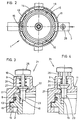
- a bayonet lock 12 which consists of an annular groove-shaped incisions 13 which are machined into the collar of the lid 11 projecting over the vessel wall 2 and which are interrupted by cutouts 14 and made on the vessel wall 2 radially directed projections 15 is formed.
- the cutouts 14 and the projections 15 are arranged evenly distributed over the circumference in such a way that the projections 15 can be inserted into the cutouts 14 and come to rest in the incisions 13 due to a slight twisting of the cover 11 1.
- a seal 8 is arranged between the container wall 2 and the cover 11, so that the pressure container 1 is closed in a gas-tight and liquid-tight manner - a pressure relief valve 21 is provided, which is formed in a receiving chamber 9 formed on the cover 11, which is connected to a vent 10 is provided, is used.
- the conical valve body 22 is pressed by the force of a valve spring 24 against a valve surface 27 attached to the cover 11 and has a pin-shaped extension 23 projecting into the pressure vessel 1.
- approximately semi-circular recesses 16 are machined in the center of the projections 15, in which the projection 23 engages. If the cover 11 placed on the pressure vessel 1 is rotated such that the shoulder 23 engages in one of the recesses 16, the cover is held against rotation and cannot be removed unintentionally.
- a grip piece 25 projecting outward from the receiving chamber 9 is formed on the valve body 22 and, as shown in FIG. 4, overrun cams 26 are attached to the receiving chamber 9, so that by lifting and turning slightly, e.g. 90 °, not only the locking of the lid 11 with the pressure vessel 1 is released, but also the valve 21 is opened and the excess pressure prevailing in the pressure vessel 1 is reduced before the lid 11 is rotated slightly without any pressure force acting on it , can be removed.
Landscapes
- Engineering & Computer Science (AREA)
- General Engineering & Computer Science (AREA)
- Mechanical Engineering (AREA)
- Filling Or Discharging Of Gas Storage Vessels (AREA)
- Containers And Packaging Bodies Having A Special Means To Remove Contents (AREA)
- Pressure Vessels And Lids Thereof (AREA)
- Self-Closing Valves And Venting Or Aerating Valves (AREA)
- Coating Apparatus (AREA)
Description
- Die Erfindung bezieht sich auf einen Druckbehälter zur Aufnahme von Flüssigkeiten, insbesondere zum kontinuierlichen Speisen eines über eine Schlauchleitung an diesen angeschlossenen Farbrollers, eines Füllpinsels, einer Düse oder dgl. mit einer unter Druck stehenden Flüssigkeit, wobei die Einfüllöffnung des Druckbehälters durch einen abnehmbaren Deckel gas- und flüssigkeitsdicht verschlossen ist, der mittels eines Bajonettverschlusses gehalten ist.
- Bei den bisher bekannten Druckbehältern dieser Art ist der im Querschnitt U-förmig ausgebildete Deckel mittels eines auf der Aussenmantelfläche des Behälters in diesen eingearbeitedes Gewinde aufgeschraubt. Obwohl zwischen diesen beiden Teilen eine Dichtung eingeklemmt ist, sind dennoch eine sichere Halterung des Deckels und ein druckdichter Verschluss oftmals nicht gegeben. Die Verschraubung kann nämlich mitunter nicht fest genug angezogen werden, auch kann sich diese durch Erschütterungen von selbst lösen, so dass in dem Druckbehälter ein Druckabbau erfolgt und eine sachgerechte Arbeitsweise somit nicht mehr möglich ist. Auch ist das Nachfüllen eines in dieser Weise ausgebildeten Druckbehälters sehr zeitaufwendig und umständlich, da an den Deckel meist Arbeitsgeräte angeschlossen sind und diese demnach abgenommen werden müssen oder zusammen mit dem Deckel mehrfach beim Abschrauben und erneuten Aufschrauben mit diesem zu verdrehen sind.
- Durch die DE-B-1 300 874 ist zwar ein Druckbehälter der eingangs genannten Art bekannt, der Bajonettverschluss ist hierbei jedoch sehr kompliziert und aufwendig ausgebildet. Bei diesem Druckbehälter wird die Einfüllöffnung von einem ringförmigen Flansch begrenzt, der durch einen Verriegelungsring verankert ist, der mit drei gleichmässig verteilt angeordneten nach oben abstehenden Vorsprüngen, die ausserdem mit nach innen geneigten Nocken ausgestattet sind, versehen ist. Des weiteren ist eine verschraubbare Nockenplatte erforderlich, um zwischen dieser und dem Flansch eine Dichtung einspannen zu können. Eine einfache Bedienbarkeit und Handhabung ist bei dieser Verschlussausgestaltung nicht gegeben, auch ist keine Sicherung gegen ungewolltes Öffnen vorgesehen.
- Aufgabe der Erfindung ist es daher, einen Druckbehälter zur Aufnahme von Flüssigkeiten der vorgenannten Gattung zu schaffen, bei dem der Deckel nicht nur leicht und in kurzer Zeit abgenommen und wiederum aufzusetzen ist, sondern der in Schliessstellung zuverlässig gehalten wird, so dass ein selbsttätiges ungewolltes Öffnen mit Sicherheit ausgeschlossen ist. Die Handhabung beim Abnehmen des Deckels und dem erneuten Verspannen soll demnach sicher und einfach sein, auch soll der Bauaufwand, um dies zu erreichen, gering gehalten werden.
- Gemäss der Erfindung wird dies bei einem Druckbehälter der vorgenannten Gattung dadurch erreicht, dass der Bajonettverschluss durch zwei oder mehrere in den Behälterdeckel eingearbeitete, vorzugsweise gleichmässig über den Umfang verteilt angeordnete und sich in Umfangsrichtung erstrekkende Einschnitte und durch diesen zugeordneten an der Behälterwandung in deren oberen Bereich eingearbeitete Vorsprüngen gebildet ist, die durch Drehen in die Einschnitte einführbar sind, und dass zur Sicherung gegen Überdruck und zur Arretierung des Behälterdeckels in Schliessstellung in diesen ein von Hand entriegelbares Überdruckventil eingesetzt ist, dessen verstellbarer Ventilkörper mit der Behälterwandung verrastbar ist.
- Um eine stets sichere Arretierung des Behälterdekkels in Schliessstellung zu gewährleisten, ist es angebracht, den Ventilkörper des Überdruckventils mit einem zentrisch angeordneten zapfenförmigen Ansatz zu versehen, der in eine in die dem Behälterdeckel zugekehrte Stirnseite der Behälterwandung eingearbeitete, vorzugsweise halbkreisförmig ausgebildete, nach innen offene Ausnehmung einführbar ist.
- Das federbelastete Überdruckventil sollte hierbei in einer in dem Behälterdeckel eingeformten entlüfteten Aufnahmekammer eingesetzt sein, an deren Stirnwand die Ventilfeder abgestützt ist, so dass dieses vor Beschädigungen geschützt ist.
- Zur Entriegelung des Überdruckventils ist es vorteilhaft, an dessen Ventilkörper ein aus der Aufnahmekammer ragendes Griffstück anzubringen unclan dieser, vorzugsweise an der oberen Stirnseite, einen oder mehrere mit dem Griffstück zusammenwirkende Auflaufnocken vorzusehen, derart, dass in einer Verdrehstellung des Griffstückes der in die Ausnehmung der Behälterwand eingreifender Ansatz ausser Eingriff gehalten wird. Der Druckbehälter wird somit, bevor der Deckel abgenommen werden kann, entlüftet und die Arretierung ist beim Verdrehen des Deckels aufgehoben, so dass das Entnehmen und Aufsetzen des Deckels ohne Schwierigkeiten vorgenommen werden kann.
- Um das Aufsetzen des Deckels zu vereinfachen, ist es des weiteren angebracht, jeden der an der Behälterwandung angeformten in eine Hinterschneidung eingreifenden Vorsprüngen jeweils eine, vorzugsweise in dessen Mitte angeordnete Ausnehmung zur Einrastung des an dem Ventilkörper angebrachten Ansatzes zu versehen.
- Ausserdem kann der Behälterdeckel mit einem vorzugsweise mittig angeordneten Bund zur Halterung und Befestigung eines in den Druckbehälter einführbaren Ansaugschlauches und der zu dem Farbroller führenden Schlauchleitung ausgestattet werden.
- Die gemäss der Erfindung vorgesehene Ausgestaltung ermöglicht es mit einfachen Mitteln, den Deckel eines Druckbehälters leicht und ohne Schwierigkeiten zu befestigen und zu lösen, ausserdem ist mit Sicherheit ausgeschlossen, dass sich der Behälterdekkel von selbst lösen kann und dass beim Abnehmen des Behälterdeckels sich noch Druckmittel in dem Behälter befindet. Wird nämlich der Deckel mittels eines in besonderer Weise ausgebildeten Bajonettverschlusses an dem Druckbehälter befestigt und wird mit Hilfe des zur Druckbegrenzung notwendigen Überdruckventils der Behälterdeckel in Schliessstellung verriegelt, so ist sichergestellt, dass der Behälterdeckel exakt arretiert ist. Eine Beschädigung der Dichtung ist somit ausgeschlossen, auch ist die Verbindung, je nach der Teilung der in die Freisparungen eingreifenden Vorsprünge nur durch eine geringe Umdrehung von beispielsweise 90° herzustellen. Und um den Deckel abnehmen zu können, ist zunächst das Überdruckventil zu entriegeln, so dass der Druckbehälter, noch bevor der Deckel abgenommen werden kann, entlüftet ist. Das Auswechseln eines Farbbehälters ist demnach in kurzer Zeit vorzunehmen, auch ist die Gefahr eines Unfalls, da ein nicht unter Überdruck stehendes Behältnis zu öffnen ist, vermieden.
- In der Zeichnung ist ein Ausführungsbeispiel eines gemäss der Erfindung ausgebildeten Druckbehälters zur Aufnahme von Flüssigkeiten dargestellt und nachfolgend im einzelnen erläutert. Hierbei zeigen:
- Fig. 1 den mit einem Farbroller versehenen Druckbehälter in Vorderansicht und teilweise im Schnitt,
- Fig. 2 einen achssenkrechten Schnitt durch den Druckbehälter nach Fig. 1 nach der Linie 11-11,
- Fig. 3 das bei dem Druckbehälter nach Fig. 1 vorgesehene, den Deckel verrastende Überdruckventil in einer vergrösserten Darstellung und
- Fig.4 das Überdruckventil nach Fig. 2 in einer anderen Betriebsstellung.
- Der in Fig.1 dargestellte und mit 1 bezeichnete, mit Standfüssen 3 versehene Druckbehälter, der durch einen aufgesetzten Deckel 11 gas- und flüssigkeitsdicht verschlossen ist, dient zur Aufnahme eines in diesem angeordneten Farbbehälters 4, aus dem Farbflüssigkeit durch den in dem Druckbehälter 1 herrschenden auf unterschiedliche Weise, beispielsweise mit Hilfe eines über einen Schalter 28 einschaltbaren Kompressors zu erzeugenden Überdruck über eine Schlauchleitung 7 einem Farbroller 6, um mit diesem aufgetragen zu werden, kontinuierlich zugeführt wird. Der Überdruck wirkt hierbei auf die in dem Farbbehältnis 4 befindliche Farbflüssigkeit ein, so dass diese durch ein an einem Bund 17 des Druckbehälters 11 befestigtes Steigrohr 5 und die ebenfalls an diesem angeschlossene Schlauchleitung 7 gefördert wird.
- Um den Deckel 11 leicht mit dem Druckbehälter 1 verbinden zu können, ist ein Bajonettverschluss 12 vorgesehen, der aus einer in den die Behälterwandung 2 überkragenden Bund des Deckels 11 eingearbeitete ringnutförmige Einschnitte 13, die durch Freisparungen 14 unterbrochen sind und durch an der Behälterwandung 2 angebrachte radial gerichtete Vorsprünge 15 gebildet ist. Die Freisparungen 14 und die Vorsprünge 15 sind gleichmässig über den Umfang derart verteilt angeordnet, dass die Vorsprünge 15 in die Freisparungen 14 einführbar und durch eine geringfügige Verdrehung des Deckels 11 1 in den Einschnitten 13 zu liegen kommen.
- Zur Verriegelung in Schliessstellung - zwischen der Behälterwandung 2 und dem Deckel 11 ist eine Dichtung 8 angeordnet, so dass der Druckbehälter 1 gas- und flüssigkeitsdicht verschlossen ist - ist ein Überdruckventil 21 vorgesehen, das in einer an dem Deckel 11 angeformten Aufnahmekammer 9, die mit einer Entlüftungsöffnung 10 versehen ist, eingesetzt ist. Der kegelig ausgebildete Ventilkörper 22 wird durch die Kraft einer Ventilfeder 24 an eine an dem Deckel 11 angebrachte Ventilfläche 27 gedrückt und weist einen in den Druckbehälter 1 ragenden bolzenförmigen Ansatz 23. auf. Und in die Behälterwandung 2 sind etwa mittig zu den Vorsprüngen 15 nach innen offene halbkreisförmige Ausnehmungen 16 eingearbeitet, in die der Ansatz 23 eingreift. Ist somit der auf den Druckbehälter 1 aufgesetzte Deckel 11 derart verdreht, dass der Ansatz 23 in eine der Ausnehmungen 16 einrastet, so ist der Deckel verdrehsicher gehalten und kann ungewollt nicht abgenommen werden.
- Zum Lösen dieser Verriegelung ist der Ansatz 23 aus der Ausnehmung 16 herauszuheben. Dazu ist an dem Ventilkörper 22 ein aus der Aufnahmekammer 9 nach aussen ragendes Griffstück 25 angeformt und an der Aufnahmekammer 9 sind, wie dies in Fig. 4 gezeigt ist, Auflaufnocken 26 angebracht, so dass durch Anheben und geringfügiges Drehen, um z.B. 90°, nicht nur die Verriegelung des Deckels 11 mit dem Druckbehälter 1 gelöst, sondern auch das Ventil 21 geöffnet wird und der in dem Druckbehälter 1 herrschende Überdruck sich abbaut, bevor der Dekkel 11 durch geringfügiges Verdrehen, ohne dass dabei auf diesen eine Druckkraft einwirkt, abgenommen werden kann.
Claims (6)
Applications Claiming Priority (2)
| Application Number | Priority Date | Filing Date | Title |
|---|---|---|---|
| DE19833305658 DE3305658A1 (de) | 1983-02-18 | 1983-02-18 | Druckbehaelter zur aufnahme von fluessigkeiten |
| DE3305658 | 1983-02-18 |
Publications (2)
| Publication Number | Publication Date |
|---|---|
| EP0116829A1 EP0116829A1 (de) | 1984-08-29 |
| EP0116829B1 true EP0116829B1 (de) | 1986-11-20 |
Family
ID=6191206
Family Applications (1)
| Application Number | Title | Priority Date | Filing Date |
|---|---|---|---|
| EP84100184A Expired EP0116829B1 (de) | 1983-02-18 | 1984-01-10 | Druckbehälter zur Aufnahme von Flüssigkeiten |
Country Status (9)
| Country | Link |
|---|---|
| US (1) | US4574988A (de) |
| EP (1) | EP0116829B1 (de) |
| JP (1) | JPS602472A (de) |
| KR (1) | KR840007944A (de) |
| AU (1) | AU2365084A (de) |
| BR (1) | BR8400591A (de) |
| DE (2) | DE3305658A1 (de) |
| ES (1) | ES529548A0 (de) |
| HU (1) | HUT34065A (de) |
Families Citing this family (22)
| Publication number | Priority date | Publication date | Assignee | Title |
|---|---|---|---|---|
| US5192425A (en) * | 1991-07-22 | 1993-03-09 | Wagner Spray Tech Corporation | Mounting base and assembly for pressure sensor, filter and pressure relief valve |
| US5251776A (en) * | 1991-08-12 | 1993-10-12 | H. William Morgan, Jr. | Pressure vessel |
| JPH0672200A (ja) * | 1992-08-31 | 1994-03-15 | Ikeda Bussan Co Ltd | 座席装置 |
| FR2701370B1 (fr) * | 1993-02-15 | 1995-04-21 | Seb Sa | Dispositif de verrouillage-déverrouillage à mâchoires d'un couvercle sur une cuve. |
| DE9304191U1 (de) * | 1993-03-20 | 1994-07-21 | Walther Spritz- und Lackiersysteme GmbH, 42327 Wuppertal | Druckgefäß, insbesondere zur Aufnahme einer Flüssigkeit wie Spritzgut für eine Farbspritzpistole |
| FR2722077B1 (fr) * | 1994-07-06 | 1996-08-23 | Seb Sa | Dispositif de verrouillage/deverrouillage a machoires d'un couvercle sur une cuve |
| US6053541A (en) * | 1998-07-14 | 2000-04-25 | Alliance Laundry Systems Llc | Automatic safety lock-out mechanism for a pressure vessel door |
| FR2783686B1 (fr) * | 1998-09-28 | 2000-11-17 | Seb Sa | Dispositif de securite a l'ouverture d'un appareil de cuisson sous pression a fermeture a baionnettes |
| ES2171337B1 (es) * | 1998-11-13 | 2003-06-16 | Fagor S Coop | Olla expres con bloqueo del cierre de la tapa. |
| US6019029A (en) * | 1999-09-09 | 2000-02-01 | Chiaphua Industries Limited | Pressure cooker |
| DE10014766C2 (de) * | 2000-03-27 | 2002-02-21 | Ursula Niese | Dampfdruck-Kochtopf |
| TW429766U (en) * | 2000-05-22 | 2001-04-11 | Chen Jin Tsai | Improved pressure pot |
| FR2836806B1 (fr) * | 2002-03-08 | 2004-09-10 | Seb Sa | Appareil de cuisson d'aliments sous pression comportant un module de couvercle |
| DE20208581U1 (de) * | 2002-06-03 | 2002-08-29 | Cheng, Tian-Jyue, Taipeh/T'ai-pei | Haltevorrichtung für Behälterdeckel |
| DE10246590A1 (de) * | 2002-10-05 | 2004-04-22 | Daimlerchrysler Ag | Behälter für flüssige und/oder gasförmige Medien und Kühlsystem für eine Brennkraftmaschine |
| FR2872015B1 (fr) * | 2004-06-29 | 2008-01-18 | Sitram | Autocuiseur avec couvercle a machoires mobiles |
| JP2010527768A (ja) * | 2007-05-23 | 2010-08-19 | エイチ、ウィリアム、モーガン、ジュニア | 安全機能がついた流体ろ過装置および方法 |
| US11950677B2 (en) | 2019-02-28 | 2024-04-09 | L'oreal | Devices and methods for electrostatic application of cosmetics |
| CN111734852B (zh) * | 2020-07-28 | 2025-03-14 | 特瑞斯能源装备股份有限公司 | 一种一体式快开盲板 |
| CN112283347B (zh) * | 2020-10-29 | 2023-03-24 | 山东克雷尔环境科技有限公司 | 一种带有增强结构耐强酸碱的玻璃钢压力容器 |
| US20220397207A1 (en) * | 2021-06-15 | 2022-12-15 | Goodrich Corporation | Port locked by pressure relief valve |
| CN114056772A (zh) * | 2021-11-29 | 2022-02-18 | 湖南康捷生物科技有限公司 | 一种具有通风结构的果胶酶存放设备 |
Family Cites Families (12)
| Publication number | Priority date | Publication date | Assignee | Title |
|---|---|---|---|---|
| US1465856A (en) * | 1922-03-16 | 1923-08-21 | Charles B Harrison | Paintbrush |
| GB351443A (de) * | 1928-12-21 | 1931-06-24 | Apollon Tchekhovitch | |
| DE928321C (de) * | 1951-12-21 | 1955-05-31 | Metall Werk Meschede G M B H | Dampfdruck-Kochtopf |
| DE957296C (de) * | 1952-07-08 | 1957-01-31 | Weston Electrical Instr Corp | Ventilgesteuerte Sicherheitsvorrichtung fuer Kessel und Druckkammern |
| US2718239A (en) * | 1952-07-08 | 1955-09-20 | Weston Electrical Instr Corp | Safety arrangement for pressure vessels |
| US3091372A (en) * | 1960-10-27 | 1963-05-28 | Root Lowell Mfg Co | Compression sprayer |
| US3158292A (en) * | 1962-12-27 | 1964-11-24 | Valve Corp Of America | Actuator for aerosol dispensers |
| DE1450288C3 (de) * | 1964-10-17 | 1973-09-13 | Blau Kg Fabrik Fuer Kraftfahrzeugteile | Bajonett-Verschlußdeckel aus elastischem Material |
| DE1277147B (de) * | 1966-03-11 | 1968-09-05 | Otto Gerhard | Sicherheitseinrichtung gegen UEberdruck und UEberfuellung bei Fluessigkeitstanks |
| BE795713A (fr) * | 1972-03-09 | 1973-06-18 | Draegerwerk Ag | Fermeture a baionnette verrouillable avec chambre de pression equipee d'un dispositif avertisseur |
| IE52823B1 (en) * | 1980-10-08 | 1988-03-16 | Black & Decker Inc | Apparatus for applying liquid to a surface |
| GB2107420B (en) * | 1981-09-28 | 1985-06-12 | British Gas Corp | Pressure lids |
-
1983
- 1983-02-18 DE DE19833305658 patent/DE3305658A1/de not_active Withdrawn
-
1984
- 1984-01-10 EP EP84100184A patent/EP0116829B1/de not_active Expired
- 1984-01-10 DE DE8484100184T patent/DE3461354D1/de not_active Expired
- 1984-01-20 AU AU23650/84A patent/AU2365084A/en not_active Abandoned
- 1984-02-08 ES ES529548A patent/ES529548A0/es active Granted
- 1984-02-10 BR BR8400591A patent/BR8400591A/pt unknown
- 1984-02-15 JP JP59025299A patent/JPS602472A/ja active Pending
- 1984-02-16 HU HU84615A patent/HUT34065A/hu unknown
- 1984-02-17 US US06/581,355 patent/US4574988A/en not_active Expired - Fee Related
- 1984-02-18 KR KR1019840000790A patent/KR840007944A/ko not_active Ceased
Also Published As
| Publication number | Publication date |
|---|---|
| BR8400591A (pt) | 1984-09-25 |
| ES8501090A1 (es) | 1984-11-16 |
| DE3305658A1 (de) | 1984-08-30 |
| DE3461354D1 (en) | 1987-01-08 |
| EP0116829A1 (de) | 1984-08-29 |
| ES529548A0 (es) | 1984-11-16 |
| US4574988A (en) | 1986-03-11 |
| JPS602472A (ja) | 1985-01-08 |
| AU2365084A (en) | 1984-08-23 |
| HUT34065A (en) | 1985-01-28 |
| KR840007944A (ko) | 1984-12-11 |
Similar Documents
| Publication | Publication Date | Title |
|---|---|---|
| EP0116829A1 (de) | Druckbehälter zur Aufnahme von Flüssigkeiten | |
| EP0977702B1 (de) | Behälterverschluss | |
| DE1482692A1 (de) | Fassanzapfvorrichtung | |
| DE8112013U1 (de) | Verschluss fuer eine Tonne oder ein Fass | |
| AT405823B (de) | Förderbüchse für eine rohrpostanlage | |
| EP2063177B1 (de) | Schneidbrenner mit einem Brennerkopf, der eine auswechselbare Schneiddüse aufnimmt | |
| EP0521461B1 (de) | Betätigungsvorrichtung für die Entnahme von Flüssigkeiten unter Druck aus einem Behälter | |
| EP0822149A1 (de) | Trinkflasche | |
| DE3316113C2 (de) | Spritzpistole | |
| DE8228745U1 (de) | Lufttrocknungseinrichtung fuer druckluftanlagen | |
| DE4202592C2 (de) | Flaschendispenser oder dergleichen mit einem Adapter zur Verbindung mit einer Flasche | |
| DE2023491A1 (de) | Filtervorrichtung | |
| DE7902130U1 (de) | An einen Wasserauslauf ansetzbarer Brausekopf mit einer Verstelleinrichtung für zwei Strahlarten | |
| EP0222736B1 (de) | Bajonettverschluss für Behälter | |
| DE2711186B2 (de) | Drehkolben-Auslaßventil, insbesondere für einen Dampfdruckkochkessel | |
| CH484382A (de) | Sicherheitsverschluss für Hochdruckbehälter | |
| DE10016805C2 (de) | Verschluß für einen Druckbehälter | |
| DE1209381B (de) | Hahn mit auswechselbarer Messblende | |
| DE107968C (de) | ||
| DE2551182C3 (de) | Nachfüllverschluß für Druck-Sprühoder Spritzgeräte | |
| DE7919024U1 (de) | Tankschraubverschluss insbesondere fuer Heizoeltanks | |
| DE10353632B3 (de) | Verbindung | |
| DE2152893B2 (de) | Sicherheitsverriegelung für den Deckel eines Druckbehälters | |
| CH696385A5 (de) | Tragbares Sprühgerät. | |
| DE4204660A1 (de) | Vorrichtung fuer die entnahme von unter dem druck eines druckgases stehenden fluessigkeiten aus einem behaelter |
Legal Events
| Date | Code | Title | Description |
|---|---|---|---|
| PUAI | Public reference made under article 153(3) epc to a published international application that has entered the european phase |
Free format text: ORIGINAL CODE: 0009012 |
|
| AK | Designated contracting states |
Designated state(s): CH DE FR GB IT LI NL |
|
| 17P | Request for examination filed |
Effective date: 19840925 |
|
| GRAA | (expected) grant |
Free format text: ORIGINAL CODE: 0009210 |
|
| AK | Designated contracting states |
Kind code of ref document: B1 Designated state(s): CH DE FR GB IT LI NL |
|
| PG25 | Lapsed in a contracting state [announced via postgrant information from national office to epo] |
Ref country code: NL Effective date: 19861120 Ref country code: IT Free format text: LAPSE BECAUSE OF FAILURE TO SUBMIT A TRANSLATION OF THE DESCRIPTION OR TO PAY THE FEE WITHIN THE PRESCRIBED TIME-LIMIT;WARNING: LAPSES OF ITALIAN PATENTS WITH EFFECTIVE DATE BEFORE 2007 MAY HAVE OCCURRED AT ANY TIME BEFORE 2007. THE CORRECT EFFECTIVE DATE MAY BE DIFFERENT FROM THE ONE RECORDED. Effective date: 19861120 Ref country code: FR Free format text: THE PATENT HAS BEEN ANNULLED BY A DECISION OF A NATIONAL AUTHORITY Effective date: 19861120 |
|
| REF | Corresponds to: |
Ref document number: 3461354 Country of ref document: DE Date of ref document: 19870108 |
|
| EN | Fr: translation not filed | ||
| NLV1 | Nl: lapsed or annulled due to failure to fulfill the requirements of art. 29p and 29m of the patents act | ||
| PLBE | No opposition filed within time limit |
Free format text: ORIGINAL CODE: 0009261 |
|
| STAA | Information on the status of an ep patent application or granted ep patent |
Free format text: STATUS: NO OPPOSITION FILED WITHIN TIME LIMIT |
|
| PG25 | Lapsed in a contracting state [announced via postgrant information from national office to epo] |
Ref country code: DE Effective date: 19871001 |
|
| 26N | No opposition filed | ||
| PGFP | Annual fee paid to national office [announced via postgrant information from national office to epo] |
Ref country code: GB Payment date: 19910206 Year of fee payment: 8 |
|
| PGFP | Annual fee paid to national office [announced via postgrant information from national office to epo] |
Ref country code: CH Payment date: 19910309 Year of fee payment: 8 |
|
| PG25 | Lapsed in a contracting state [announced via postgrant information from national office to epo] |
Ref country code: GB Effective date: 19920110 |
|
| PG25 | Lapsed in a contracting state [announced via postgrant information from national office to epo] |
Ref country code: LI Effective date: 19920131 Ref country code: CH Effective date: 19920131 |
|
| GBPC | Gb: european patent ceased through non-payment of renewal fee | ||
| REG | Reference to a national code |
Ref country code: CH Ref legal event code: PL |