EP0110476B1 - Anordnung zur Verschiebung eines Geräteteils an einem Röntgengerät mittels einer endlosen Kette - Google Patents
Anordnung zur Verschiebung eines Geräteteils an einem Röntgengerät mittels einer endlosen Kette Download PDFInfo
- Publication number
- EP0110476B1 EP0110476B1 EP83201676A EP83201676A EP0110476B1 EP 0110476 B1 EP0110476 B1 EP 0110476B1 EP 83201676 A EP83201676 A EP 83201676A EP 83201676 A EP83201676 A EP 83201676A EP 0110476 B1 EP0110476 B1 EP 0110476B1
- Authority
- EP
- European Patent Office
- Prior art keywords
- chain
- guide
- ray apparatus
- sprockets
- table top
- Prior art date
- Legal status (The legal status is an assumption and is not a legal conclusion. Google has not performed a legal analysis and makes no representation as to the accuracy of the status listed.)
- Expired
Links
- 238000006073 displacement reaction Methods 0.000 claims description 3
- 230000008878 coupling Effects 0.000 description 5
- 238000010168 coupling process Methods 0.000 description 5
- 238000005859 coupling reaction Methods 0.000 description 5
- 230000003068 static effect Effects 0.000 description 3
- 238000010276 construction Methods 0.000 description 1
Images

Classifications
-
- A—HUMAN NECESSITIES
- A61—MEDICAL OR VETERINARY SCIENCE; HYGIENE
- A61B—DIAGNOSIS; SURGERY; IDENTIFICATION
- A61B6/00—Apparatus or devices for radiation diagnosis; Apparatus or devices for radiation diagnosis combined with radiation therapy equipment
- A61B6/10—Safety means specially adapted therefor
-
- A—HUMAN NECESSITIES
- A61—MEDICAL OR VETERINARY SCIENCE; HYGIENE
- A61B—DIAGNOSIS; SURGERY; IDENTIFICATION
- A61B6/00—Apparatus or devices for radiation diagnosis; Apparatus or devices for radiation diagnosis combined with radiation therapy equipment
- A61B6/04—Positioning of patients; Tiltable beds or the like
-
- F—MECHANICAL ENGINEERING; LIGHTING; HEATING; WEAPONS; BLASTING
- F16—ENGINEERING ELEMENTS AND UNITS; GENERAL MEASURES FOR PRODUCING AND MAINTAINING EFFECTIVE FUNCTIONING OF MACHINES OR INSTALLATIONS; THERMAL INSULATION IN GENERAL
- F16H—GEARING
- F16H49/00—Other gearings
-
- Y—GENERAL TAGGING OF NEW TECHNOLOGICAL DEVELOPMENTS; GENERAL TAGGING OF CROSS-SECTIONAL TECHNOLOGIES SPANNING OVER SEVERAL SECTIONS OF THE IPC; TECHNICAL SUBJECTS COVERED BY FORMER USPC CROSS-REFERENCE ART COLLECTIONS [XRACs] AND DIGESTS
- Y10—TECHNICAL SUBJECTS COVERED BY FORMER USPC
- Y10S—TECHNICAL SUBJECTS COVERED BY FORMER USPC CROSS-REFERENCE ART COLLECTIONS [XRACs] AND DIGESTS
- Y10S5/00—Beds
- Y10S5/943—Beds with horizontally movable top surface
Definitions
- the invention relates to an arrangement according to the preamble of the main claim.
- the device part is a table top of an X-ray examination device.
- the chain wheel is driven by a motor if necessary. If the drive is switched off in such a device, the drivable chain wheel is blocked so that the device part can remain in the respective position.
- the chain is loaded by the forces acting on the device part and additionally by the motor drive. Breaking the chain can endanger the patient.
- legal regulations IEC 601-1, 28.3; VDE 0750, Part 1
- VDE 0750, Part 1 there are legal regulations that effectively require a twelve-fold static safety if there is no additional safety device that prevents one If the rope breaks, the device part falls down. This means that the chain must be designed for a factor of ten times the static load on the device part that occurs during normal operation.
- the object of the present invention is to design an arrangement of the type mentioned at the outset such that the device part can only move slightly in the event of a chain break. According to the invention, this object is achieved by the measures specified in the characterizing part of the main claim.
- the rigid guide surrounds the chain on all sides so that it moves in a lateral direction, i.e. can move only slightly in the direction perpendicular to the tangent to the chain at the point in question. If the chain breaks - and this break usually takes place in the part of the chain that is subject to tension - the device part exerts pressure on the other part of the chain, which the chain can hardly avoid laterally, however, because Leadership is prevented. As a result, the chain absorbs the compressive force and practically holds the device part in the position it was in before the chain broke.
- the guide can consist of several parts which individually enclose the drivable sprocket - and another sprocket required to deflect the chain - and the parts of the chain lying between the sprockets.
- the guide is designed as a hollow profile rail with recesses for the chain wheels and with channels for the chains.
- the hollow profile rail serves to guide the table top.
- the hollow profile rail has two functions: it serves to guide the table top and, together with the chain, secures the table top against falling.
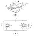
- Fig. 1 an X-ray examination device is shown, the frame 1 is pivotally mounted about a horizontal axis in a foot structure 2.
- the frame carries one parallel to the swivel axis, i.e. in the direction of the double arrow 5, movable cross carriage 4, which is provided with two parallel guide rails 6, which run perpendicular to the pivot axis and for guiding a table top 3 in its longitudinal direction, i.e. serve in the direction of the double arrow 7.
- the X-ray examination device also includes an X-ray target device 8.
- the displacement of the table top 3 takes place with the aid of a chain, not shown in FIG. 1, on which a motor acts, neither of which is shown, via a chain wheel.
- a motor acts, neither of which is shown, via a chain wheel.
- the sprocket it drives is blocked - for example, because the motor is coupled to the sprocket via a self-locking gear or because it is designed as a brake motor - so that the table top maintains its position, even then when it is vertical and by the patient, e.g. over a footstool.
- the X-ray examination device is known.
- FIGS. 2 and 3 show cross sections of a guide rail 6, specifically in the direction perpendicular to the table top (FIG. 2) and in a plane parallel to the table top (FIG. 3).
- the guide rail is designed as a hollow profile rail with two channels 9 with a rectangular cross section running in the longitudinal direction of the rail.
- cylindrical recesses 10 are provided, in each of which a sprocket 11 or 12 runs, the sprocket 12 being coupled to a drive motor, not shown.
- a roller chain 13, for example according to DIN 8187, is guided around the two sprockets and runs in the channels 9; only a few links of this chain are indicated in the drawing.
- a coupling device 14 is connected to this roller chain, which projects out of a slot 15 running in the longitudinal direction of the rail and is connected to one side of the table top 3.
- the dimensions of the slot are smaller than the dimensions of a chain link, so that the chain can under no circumstances emerge from the side of the slot.
- the dimensions of the recesses 10 and the channels 9 are matched to the dimensions of the sprockets 11 and 12 and the chain 13 in such a way that the chain is everywhere at a short distance (for example 1 mm) from the one surrounding it Walls of the hollow profile passes.
- the weight of the table top acts via the coupling device 14 the chain 13 a.
- the part located between the coupling device 14 and the sprocket serving the deflection and the (left) part connecting the two sprockets directly to one another are subjected to tension, while the remaining part (between the coupling device 14 and the drivable sprocket 12) only corresponds to the pretension the chain is loaded.
- the table top cannot fall off if the chain breaks. According to the legal provisions, the chain 13 therefore only has to be designed for four times the maximum static load; it can therefore be relatively thin.
- the second guide rail can be arranged mirror-symmetrically, so that the slots in the two rails face away from the other rail.
- the chain wheels must then be driven at the same speed, but with the opposite direction of rotation.
Landscapes
- Health & Medical Sciences (AREA)
- Life Sciences & Earth Sciences (AREA)
- Engineering & Computer Science (AREA)
- Medical Informatics (AREA)
- Radiology & Medical Imaging (AREA)
- Molecular Biology (AREA)
- Biophysics (AREA)
- Nuclear Medicine, Radiotherapy & Molecular Imaging (AREA)
- Optics & Photonics (AREA)
- Pathology (AREA)
- Physics & Mathematics (AREA)
- Biomedical Technology (AREA)
- Heart & Thoracic Surgery (AREA)
- High Energy & Nuclear Physics (AREA)
- Surgery (AREA)
- Animal Behavior & Ethology (AREA)
- General Health & Medical Sciences (AREA)
- Public Health (AREA)
- Veterinary Medicine (AREA)
- General Engineering & Computer Science (AREA)
- Mechanical Engineering (AREA)
- Apparatus For Radiation Diagnosis (AREA)
- Radiography Using Non-Light Waves (AREA)
Applications Claiming Priority (2)
| Application Number | Priority Date | Filing Date | Title |
|---|---|---|---|
| DE19823244578 DE3244578A1 (de) | 1982-12-02 | 1982-12-02 | Anordnung zur verschiebung eines geraeteteils an einem roentgengeraet mittels einer endlosen kette |
| DE3244578 | 1982-12-02 |
Publications (3)
| Publication Number | Publication Date |
|---|---|
| EP0110476A2 EP0110476A2 (de) | 1984-06-13 |
| EP0110476A3 EP0110476A3 (en) | 1984-07-25 |
| EP0110476B1 true EP0110476B1 (de) | 1987-04-22 |
Family
ID=6179613
Family Applications (1)
| Application Number | Title | Priority Date | Filing Date |
|---|---|---|---|
| EP83201676A Expired EP0110476B1 (de) | 1982-12-02 | 1983-11-29 | Anordnung zur Verschiebung eines Geräteteils an einem Röntgengerät mittels einer endlosen Kette |
Country Status (4)
| Country | Link |
|---|---|
| US (1) | US4615042A (enExample) |
| EP (1) | EP0110476B1 (enExample) |
| JP (1) | JPS59111743A (enExample) |
| DE (2) | DE3244578A1 (enExample) |
Families Citing this family (9)
| Publication number | Priority date | Publication date | Assignee | Title |
|---|---|---|---|---|
| DE8620535U1 (de) * | 1986-07-31 | 1987-11-26 | Siemens AG, 1000 Berlin und 8000 München | Patientenlagerungstisch |
| US4805626A (en) * | 1986-11-26 | 1989-02-21 | Fonar Corporation | Air flotation patient bed |
| JPH04114634A (ja) * | 1990-09-04 | 1992-04-15 | Toshiba Corp | 医療診断用寝台 |
| US5131105A (en) * | 1990-11-21 | 1992-07-21 | Diasonics, Inc. | Patient support table |
| US5230112A (en) * | 1990-11-21 | 1993-07-27 | Diasonics, Inc. | Patient support table |
| JP3260449B2 (ja) * | 1992-10-22 | 2002-02-25 | 株式会社東芝 | X線診断装置 |
| DE19518572A1 (de) * | 1995-05-20 | 1996-11-21 | Dornier Medizintechnik | Urologietisch |
| US6526609B2 (en) * | 2001-03-29 | 2003-03-04 | William Beaumont Hospital | X-ray transparent hospital bed compatible with open geometry portable CT scanners |
| CN100463656C (zh) * | 2006-04-29 | 2009-02-25 | 东软飞利浦医疗设备系统有限责任公司 | 一种x射线机床体运动限位保护装置 |
Family Cites Families (12)
| Publication number | Priority date | Publication date | Assignee | Title |
|---|---|---|---|---|
| DE352059C (de) * | 1922-04-20 | Siemens & Halske Akt Ges | Heb- und senkbarer Tisch fuer Roentgenbestrahlungen | |
| DE688182C (de) * | 1935-12-22 | 1940-02-14 | Karl Salomon | Druckkettengetriebe |
| US2252336A (en) * | 1939-12-19 | 1941-08-12 | Charles E Thomas | Grain binder |
| US3029957A (en) * | 1958-01-10 | 1962-04-17 | Freeman | Handling device for presses |
| DE1222624B (de) * | 1959-12-21 | 1966-08-11 | Koch & Sterzel Kommanditgesell | Roentgenuntersuchungsgeraet mit einer um eine horizontale Achse schwenkbaren Patientenlagerungsplatte |
| US3472085A (en) * | 1967-08-21 | 1969-10-14 | Melville S Rosen | Motion transmitting mechansim |
| US3473024A (en) * | 1967-10-23 | 1969-10-14 | Gen Electric | X-ray tabletop extension and tilt control |
| US3588500A (en) * | 1968-11-22 | 1971-06-28 | Westinghouse Electric Corp | X-ray table with selective float and power drive top |
| US3624398A (en) * | 1969-09-25 | 1971-11-30 | Weldon D Arndt | Serial radiograph table |
| DE2205767A1 (de) * | 1972-02-08 | 1973-08-09 | Wagner Maschf Paul Heinz | Drehmomenten-uebertragungsgetriebe |
| US4164656A (en) * | 1977-05-20 | 1979-08-14 | U.S. Philips Corporation | Parallel safety coupling for X-ray table tilt drive |
| BE889159A (nl) * | 1981-06-10 | 1981-10-01 | Cgr Benelux N V | Inrichting voor het roterend aandrijven van een strooistralenraster in een rontgentomograaf |
-
1982
- 1982-12-02 DE DE19823244578 patent/DE3244578A1/de not_active Withdrawn
-
1983
- 1983-11-21 US US06/554,139 patent/US4615042A/en not_active Expired - Fee Related
- 1983-11-29 DE DE8383201676T patent/DE3371037D1/de not_active Expired
- 1983-11-29 EP EP83201676A patent/EP0110476B1/de not_active Expired
- 1983-12-01 JP JP58227792A patent/JPS59111743A/ja active Granted
Also Published As
| Publication number | Publication date |
|---|---|
| EP0110476A3 (en) | 1984-07-25 |
| EP0110476A2 (de) | 1984-06-13 |
| US4615042A (en) | 1986-09-30 |
| JPH0417657B2 (enExample) | 1992-03-26 |
| JPS59111743A (ja) | 1984-06-28 |
| DE3244578A1 (de) | 1984-06-07 |
| DE3371037D1 (en) | 1987-05-27 |
Similar Documents
| Publication | Publication Date | Title |
|---|---|---|
| DE2810941C3 (de) | Vorrichtung zum Prüfen von Glasbehältern | |
| EP0110476B1 (de) | Anordnung zur Verschiebung eines Geräteteils an einem Röntgengerät mittels einer endlosen Kette | |
| DE2301349A1 (de) | Vorrichtung zum auseinanderhalten von zwei greifern | |
| EP0941889B1 (de) | Ausziehvorrichtung | |
| DE2646291B2 (de) | Zahnstange für Gewinnungsmaschinen des Untertagebergbaues, insbesondere für Walzenschrämmaschinen | |
| DE3536554C2 (de) | Schiebetor | |
| EP2530234A1 (de) | Antriebsvorrichtung zum Verstellen von Sonnenschutzanlagen | |
| EP0499630B1 (de) | Umlenkstation für förderbänder | |
| DE3024803A1 (de) | Transportvorrichtung, insbes. fuer verpackungsmaschinen | |
| CH644545A5 (en) | Universal manipulator for in-service inspection at reactor pressure vessels | |
| EP2261164A2 (de) | Führungseinrichtung mit Mitten- und Geradlaufregelung für einen mit Laufrädern versehenen Kran auf einer Kranbahn mit Kranschienen | |
| EP0173182B1 (de) | Hub- und Schwenkvorrichtung für den Austragsabschnitt einer rohrförmigen Schuttrutsche | |
| DE2740211C2 (de) | Vorrichtung zum Antreiben eines Paares Greiferschienen in Längsrichtung | |
| DE2828871C2 (de) | Zuführvorrichtung für gegurtete Munition | |
| EP0144946A2 (de) | Vorrichtung zum Abstellen von Kraftfahrzeugen | |
| CH672667A5 (enExample) | ||
| DE1241355B (de) | Einrichtung zum Verschieben von Lagerregalen od. dgl. | |
| DE19625477C1 (de) | Flüssigkeitsbarriere zum dichten Abschluß des unteren Bereiches einer Maueröffnung oder dergleichen | |
| EP0103852A1 (de) | Linearantrieb | |
| DE4142061A1 (de) | Geradefuehrungseinheit mit synchron verschobenem waelzlagerelement-kaefig | |
| EP0187976A2 (de) | Verriegelungsvorrichtung für die aneinander zwangsgeführten Teleskopschüsse eines Aufzuges | |
| DE2733803C3 (de) | Rollenfenster zur Seilführung bei Seilbahnen des Untertagebetriebes | |
| DD291524A5 (de) | Rollenbahn mit veraenderbarer transportlaenge | |
| DE2235350A1 (de) | Ziehvorrichtung zur laengsbewegung laenglichen materials | |
| DE3245602C1 (de) | Einrichtung zum Schutz und zur Fuehrung des Zugmittels und der Versorgungsleitungen einer Bergbau-Gewinnungsmaschine |
Legal Events
| Date | Code | Title | Description |
|---|---|---|---|
| PUAI | Public reference made under article 153(3) epc to a published international application that has entered the european phase |
Free format text: ORIGINAL CODE: 0009012 |
|
| PUAL | Search report despatched |
Free format text: ORIGINAL CODE: 0009013 |
|
| AK | Designated contracting states |
Designated state(s): BE DE FR GB IT |
|
| AK | Designated contracting states |
Designated state(s): BE DE FR GB IT |
|
| 17P | Request for examination filed |
Effective date: 19840823 |
|
| GRAA | (expected) grant |
Free format text: ORIGINAL CODE: 0009210 |
|
| AK | Designated contracting states |
Kind code of ref document: B1 Designated state(s): BE DE FR GB IT |
|
| REF | Corresponds to: |
Ref document number: 3371037 Country of ref document: DE Date of ref document: 19870527 |
|
| ITF | It: translation for a ep patent filed | ||
| ET | Fr: translation filed | ||
| RAP2 | Party data changed (patent owner data changed or rights of a patent transferred) |
Owner name: N.V. PHILIPS' GLOEILAMPENFABRIEKEN Owner name: PHILIPS PATENTVERWALTUNG GMBH |
|
| BECN | Be: change of holder's name |
Effective date: 19870422 |
|
| PLBE | No opposition filed within time limit |
Free format text: ORIGINAL CODE: 0009261 |
|
| STAA | Information on the status of an ep patent application or granted ep patent |
Free format text: STATUS: NO OPPOSITION FILED WITHIN TIME LIMIT |
|
| 26N | No opposition filed | ||
| PGFP | Annual fee paid to national office [announced via postgrant information from national office to epo] |
Ref country code: BE Payment date: 19901107 Year of fee payment: 8 |
|
| PG25 | Lapsed in a contracting state [announced via postgrant information from national office to epo] |
Ref country code: BE Effective date: 19911130 |
|
| BERE | Be: lapsed |
Owner name: N.V. PHILIPS' GLOEILAMPENFABRIEKEN Effective date: 19911130 Owner name: PHILIPS PATENTVERWALTUNG G.M.B.H. Effective date: 19911130 |
|
| ITTA | It: last paid annual fee | ||
| ITPR | It: changes in ownership of a european patent |
Owner name: CAMBIO RAGIONE SOCIALE;PHILIPS ELECTRONICS N.V. |
|
| REG | Reference to a national code |
Ref country code: FR Ref legal event code: CD |
|
| PGFP | Annual fee paid to national office [announced via postgrant information from national office to epo] |
Ref country code: GB Payment date: 19951101 Year of fee payment: 13 |
|
| PGFP | Annual fee paid to national office [announced via postgrant information from national office to epo] |
Ref country code: FR Payment date: 19951129 Year of fee payment: 13 |
|
| PGFP | Annual fee paid to national office [announced via postgrant information from national office to epo] |
Ref country code: DE Payment date: 19960125 Year of fee payment: 13 |
|
| PG25 | Lapsed in a contracting state [announced via postgrant information from national office to epo] |
Ref country code: GB Effective date: 19961129 |
|
| GBPC | Gb: european patent ceased through non-payment of renewal fee |
Effective date: 19961129 |
|
| PG25 | Lapsed in a contracting state [announced via postgrant information from national office to epo] |
Ref country code: FR Effective date: 19970731 |
|
| PG25 | Lapsed in a contracting state [announced via postgrant information from national office to epo] |
Ref country code: DE Effective date: 19970801 |
|
| REG | Reference to a national code |
Ref country code: FR Ref legal event code: ST |