EP0098973B1 - Verschluss für flexible Behälter - Google Patents
Verschluss für flexible Behälter Download PDFInfo
- Publication number
- EP0098973B1 EP0098973B1 EP83105613A EP83105613A EP0098973B1 EP 0098973 B1 EP0098973 B1 EP 0098973B1 EP 83105613 A EP83105613 A EP 83105613A EP 83105613 A EP83105613 A EP 83105613A EP 0098973 B1 EP0098973 B1 EP 0098973B1
- Authority
- EP
- European Patent Office
- Prior art keywords
- shell
- closure according
- wrapping bar
- bar
- wrapping
- Prior art date
- Legal status (The legal status is an assumption and is not a legal conclusion. Google has not performed a legal analysis and makes no representation as to the accuracy of the status listed.)
- Expired
Links
Images
Classifications
-
- B—PERFORMING OPERATIONS; TRANSPORTING
- B65—CONVEYING; PACKING; STORING; HANDLING THIN OR FILAMENTARY MATERIAL
- B65D—CONTAINERS FOR STORAGE OR TRANSPORT OF ARTICLES OR MATERIALS, e.g. BAGS, BARRELS, BOTTLES, BOXES, CANS, CARTONS, CRATES, DRUMS, JARS, TANKS, HOPPERS, FORWARDING CONTAINERS; ACCESSORIES, CLOSURES, OR FITTINGS THEREFOR; PACKAGING ELEMENTS; PACKAGES
- B65D33/00—Details of, or accessories for, sacks or bags
- B65D33/16—End- or aperture-closing arrangements or devices
- B65D33/1658—Elements for flattening or folding the mouth portion
- B65D33/1666—Slitted tubes with or without a core; U-shaped clips made of one piece
-
- B—PERFORMING OPERATIONS; TRANSPORTING
- B65—CONVEYING; PACKING; STORING; HANDLING THIN OR FILAMENTARY MATERIAL
- B65D—CONTAINERS FOR STORAGE OR TRANSPORT OF ARTICLES OR MATERIALS, e.g. BAGS, BARRELS, BOTTLES, BOXES, CANS, CARTONS, CRATES, DRUMS, JARS, TANKS, HOPPERS, FORWARDING CONTAINERS; ACCESSORIES, CLOSURES, OR FITTINGS THEREFOR; PACKAGING ELEMENTS; PACKAGES
- B65D33/00—Details of, or accessories for, sacks or bags
- B65D33/16—End- or aperture-closing arrangements or devices
- B65D33/1658—Elements for flattening or folding the mouth portion
Definitions
- the invention relates to a closure for flexible containers made of tubular or sack-shaped semifinished products for transporting and storing flowable or pourable goods, with a clamping device comprising a plurality of bars which can be fixed against one another and an unwinding device arranged on the circumference of a winding rod for the container opening to be closed, which in particular has a rod.
- Such containers have a volume of 1000 l or 2000 l, for example, and are primarily intended for use in the event of a disaster. For example, they can be used to supply the population with drinking water. However, they are also suitable, for example, for storing drinking water or waste water on ships or for storing other liquids.
- the containers are generally transported by truck, the permissible total weight of which must not be exceeded. As a result, when using smaller load paths, it may be necessary not to fill the container completely. In this case, however, dynamic inertial forces of the liquid can endanger the vehicle while driving, so that a closure is required which reduces or completely eliminates the free volume.
- closure It is also necessary to make the closure as easy to use as possible, especially for rapid use in the event of a disaster. Finally, in some cases it may be necessary to design the closure to be as space-saving as possible, for example to enable stacking of several containers.
- a closure suitable for this purpose is known for example from DE-OS 30 04 884.
- the closure described in this document consists of clamping bodies arranged one above the other in side holders, through the separating joints of which one end of the semifinished product is passed.
- the clamping bodies are arranged to be displaceable relative to one another and can be braced against one another with a clamping device that can be inserted into each holder.
- a disadvantage of this known closure is given by the construction of a relatively large number of individual parts, which complicate its handling and increase the susceptibility to faults.
- the dimensions of this closure are relatively large, so that stacking of several containers on top of one another is severely hindered.
- the dimensions of the closure are particularly disadvantageous for containers with a small capacity.
- the closure mentioned above is known from FR-PS 1 458 178.
- This closure has a winding rod, around which the container opening of the container to be closed is wound, an additional clamping body being applied laterally after the wrapping.
- an unwinding device in the form of a clamp element is pushed onto the winding bar.
- a corresponding closure is known from FR-PS 78 061.
- a disadvantage of this known closure is also the construction of a relatively large number of individual parts, which complicate its handling and increase the susceptibility to faults.
- a major disadvantage is that with the known winding rod, the container opening to be closed can be wound up only with difficulty and with difficulty, special care being taken to avoid oblique winding.
- the sealing effect when winding onto the known winding rod is not always guaranteed, and leaks can occur in the container, in particular if the internal pressure is high.
- the known unwinding protection is also not able to counteract these disadvantages, which, moreover, is very difficult to handle with the known winding rod.
- the object of the invention is to provide an improved closure which facilitates the winding of the container opening to be closed and which ensures perfect sealing properties at all times, even with high internal pressure in the container.
- the winding rod has a slot so that an upper part and a lower part of the container can be inserted into the slot and with at least two deflections around the edges of the winding rod formed by the slot by at least 270 ° are tight and wrinkle-free.
- the advantage of this closure is that the wrap in the winding rod makes it easier to wind up the container opening to be closed. For winding up, the container opening only needs to be pushed into the slot, and the container opening can no longer slip on the winding rod when the winding rod is rotated by 90 °. In particular, it is very easy with the slot to roll up the container opening several times around the winding rod if a smaller volume is required in the container. Another advantage is that the slot forms a clamping edge that seals the container perfectly even at high internal pressures. Finally, the closure consists of only a few parts and is therefore hardly susceptible to failure. In addition, it has a significantly lower weight compared to the known var closures.
- the unwind protection is formed by a rod-shaped tensioning element which is connected to the winding bar by means of tensioning screws.
- the clamping element can be designed as a rail with a U-shaped profile, the slotted winding rod partially or completely.
- the unwind protection can also be formed by two opposing rectangular tubes or profiled rods which are connected to one another by means of tensioning screws leading through the slotted winding rod outside the slot length of the winding rod.
- the unwinding protection is formed by a sleeve which firmly encompasses the wound container opening and can be pushed onto the winding rod and which, in the pushed-on state, is fixed non-rotatably with respect to the winding rod.
- the unwinding protection as a sleeve
- a quick and reliable fixation of the container opening wound on the winding rod is achieved. Additional elements such as Tensioning screws, which can be lost when the closure is open and during cleaning of the container, are not required.
- the sleeve can be pushed onto the winding rod in the axial direction. Since it is fixed so that it cannot be rotated when it is pushed open, the wound-up container opening does not come loose on its own, so that the container is closed properly at all times. The handling of the closure is even easier and the susceptibility to faults is reduced.
- the sleeve on the winding rod is held non-rotatably as a result of a profile cross section of both the sleeve and the winding rod that deviates from the circular shape.
- the profile cross section of the sleeve and the profile cross section of the winding rod can be rectangular, in particular square, or oval. This special design of the profile cross-sections means that there is no need for an additional anti-rotation lock.
- the sleeve is held non-rotatably on the winding bar by means of anti-rotation devices engaging in both parts.
- the end of the sleeve can be provided with a notch into which, after the sleeve has been pushed open, a pin arranged at the corresponding end of the winding rod and extending in the radial direction engages as a rotation lock.
- This embodiment opens up the possibility of also using winding rods and sleeves with a round cross section.
- the longitudinal slide also serves as a notch, this preferably being used at both ends of the sleeve for receiving one pin each, which is arranged at the two ends of the winding rod.
- the longitudinal slot together with the pins serves as a guide for pushing the sleeve onto the winding rod. This prevents the sleeve from twisting relative to the winding bar during the sliding on.
- the sleeve consists of an elastic material and is in frictional connection with the outside of the wound-up container opening.
- the height of the longitudinal slot is preferably somewhat less than the height of the flattened container opening, the longitudinal edges of the longitudinal slot of the sleeve abutting the upper and lower part of the container after being pushed open. This makes it difficult to inadvertently move the sleeve in the pushed-open state relative to the winding rod.
- the opening opposite the front entry opening of the sleeve is closed by a plate.
- This plate serves as a stop, which ensures easy positioning in the axial direction when the sleeve is pushed onto the winding rod.
- two,. the two ends of the winding rod are slidable sleeves, the length of which is less than half the total length of the winding rod. This simplifies the fixing of the container opening wound on the winding rod, since it is not necessary to slide on a sleeve corresponding to the total length of the winding rod, but only two small sleeves which are pushed onto the two ends of the winding rod. This is particularly advantageous with wide container openings if, due to the length of the sleeve, a large frictional resistance occurs when pushed on.
- the sleeve has a U-shaped profile cross section and can be pushed on transversely to the axial direction of the winding rod, with a displacement lock being arranged at the two ends of the sleeve.
- a locking bolt that is anchored to the sleeve and rotatable and engages behind the winding bar can be provided to prevent displacement.
- a ring that can be pushed onto the end is also conceivable as a displacement device.
- the U-shaped sleeve is used when wide container openings have to be closed, which would lead to high frictional resistance if the sleeve were moved axially.
- the edge of the container opening protruding into the slot of the winding rod is arranged within the winding rod. This avoids disturbing elevations of the wound container opening, which make it difficult, if not impossible, to slide the sleeve open.
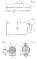
- the bag-shaped, flexible container 1 shown in FIGS. 1 and 2 consists of an upper part 2 and a lower part 3, which on their two longitudinal sides and on one end face are joined to form a common edge 5, for example glued or welded to one another.
- the upper part 2 is provided with a filling opening 4.
- the second end face of the container 1 serves as a container opening 7, which opens into a neck 6.
- the container opening 7 is closed by a closure 8.
- the neck 6 When the container 1 is closed, the neck 6 is guided through a winding rod 10 provided with a slot 9 in the middle and then wound tightly and without folds by at least 360 ° in the embodiment shown in FIG. 3 by rotating the winding rod 10 in the direction toward the center of the container .
- the layers of the container opening 7 can also overlap by repeated turning.
- the neck 6, as can be seen in FIG. 3, is deflected at several points.
- the rotation achieved can be fixed by tightening clamping screws 13, which are suitably provided near the ends of the winding rod 10.
- the clamping screws 13 lead through a clamping device 11 forming clamping element 12 with a U-profile and through the winding rod 10 and are z. B. tightened by a mother.
- the fixing element has the shape of two rectangular tubes 14, which are connected with tensioning screws 15, which lead through the winding rod 10 outside the area of the slot 9.
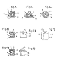
- FIG. 5 to 9 show further embodiments of the closure 8, which differ in particular by the fixing element.
- the flattened container opening 7 of the empty container 1 is in turn pushed into the slot 9 of the winding rod 10, the edge of the container opening 7 coming to rest within the winding rod 10.
- a sleeve 16 with a longitudinal slot 21 is pushed onto the winding rod 10 in the axial direction by firmly gripping the wound container opening 7.
- the longitudinal slot 21 of this sleeve 16 comes with its two longitudinal edges on the upper part 2 and the lower part 3 of the container 1 to the plant.
- both the winding rod 10 and the sleeve 16 have a rectangular profile cross section, so that both parts are non-rotatably fixed to each other. In this way, the container opening 7 is closed, the pushed-on sleeve 16 ensuring that the container opening 7 no longer detaches from the winding rod 10.
- the profile cross sections of both the winding bars 10 and the sleeve 16 are triangular.
- the two parts are fixed in a non-rotatable manner.
- the winding rod 10 and the sleeve 16 have a round profile cross section, so that an additional anti-rotation device must be provided in this embodiment.
- Fig. 7b The end of the sleeve 16 is provided with a notch 20, in which, after the sleeve 16 has been pushed on, a pin 19 arranged at the corresponding end of the winding rod 10 and extending in the radial direction engages as an anti-rotation device.
- the longitudinal slot 21 in the sleeve 16 can also serve as the notch 20. In this case, the longitudinal slot 21 also serves as a guide for pushing on the sleeve 16.
- the sleeve 16 has a U-shaped profile cross section and is pushed on transversely to the axial direction of the winding rod 10, that is to say from the right in the drawing.
- an additional locking device is provided.
- Fig. 8b is a bar 17 rotatably arranged on the sleeve 16, which is in the dashed position before and during the sliding of the sleeve 16 on the winding rod 10. After being pushed on, the bolt 17 is rotated downward and thus prevents the sleeve 16 from coming loose.
- Fig. 9a and 9b in which a clip-like ring 18 is pushed onto each of the ends of the sleeve 16.
- the container 1 is bag-shaped, so that only one closure 8 is required.
- the volume of the container 1 can thus be reduced to a certain volume from two sides.
Priority Applications (2)
| Application Number | Priority Date | Filing Date | Title |
|---|---|---|---|
| AT83105613T ATE19498T1 (de) | 1982-07-09 | 1983-06-08 | Verschluss fuer flexible behaelter. |
| KE378287A KE3782A (en) | 1982-07-09 | 1987-10-23 | Closure device for flexible containers |
Applications Claiming Priority (4)
| Application Number | Priority Date | Filing Date | Title |
|---|---|---|---|
| DE3225681 | 1982-07-09 | ||
| DE3225681A DE3225681C1 (de) | 1982-07-09 | 1982-07-09 | Verschluß für flexible Behälter |
| DE3313004 | 1983-04-12 | ||
| DE19833313004 DE3313004A1 (de) | 1983-04-12 | 1983-04-12 | Verschluss fuer flexible behaelter |
Publications (3)
| Publication Number | Publication Date |
|---|---|
| EP0098973A2 EP0098973A2 (de) | 1984-01-25 |
| EP0098973A3 EP0098973A3 (en) | 1984-06-06 |
| EP0098973B1 true EP0098973B1 (de) | 1986-04-30 |
Family
ID=25802935
Family Applications (1)
| Application Number | Title | Priority Date | Filing Date |
|---|---|---|---|
| EP83105613A Expired EP0098973B1 (de) | 1982-07-09 | 1983-06-08 | Verschluss für flexible Behälter |
Country Status (20)
| Country | Link |
|---|---|
| EP (1) | EP0098973B1 (pt) |
| AU (1) | AU563947B2 (pt) |
| BR (1) | BR8303680A (pt) |
| CA (1) | CA1222728A (pt) |
| CS (1) | CS253576B2 (pt) |
| DD (1) | DD210007A5 (pt) |
| DE (1) | DE3363264D1 (pt) |
| DK (1) | DK154131C (pt) |
| EG (1) | EG15961A (pt) |
| ES (3) | ES281456Y (pt) |
| FI (1) | FI76983C (pt) |
| GR (1) | GR77504B (pt) |
| HU (1) | HU186720B (pt) |
| IL (1) | IL69120A (pt) |
| MX (1) | MX158907A (pt) |
| NO (1) | NO162806C (pt) |
| PT (1) | PT76947B (pt) |
| RO (1) | RO88372A (pt) |
| TR (1) | TR21547A (pt) |
| YU (1) | YU43318B (pt) |
Cited By (1)
| Publication number | Priority date | Publication date | Assignee | Title |
|---|---|---|---|---|
| DE29609802U1 (de) * | 1996-06-03 | 1996-08-14 | Pro Pack Handels Und Vertriebs | Sackverschluß |
Families Citing this family (2)
| Publication number | Priority date | Publication date | Assignee | Title |
|---|---|---|---|---|
| DE3500803A1 (de) * | 1985-01-11 | 1986-07-17 | Pietro Crema Cremona Mariani | Geraet zum vakuumverpacken von lebensmitteln und anderen gegenstaenden |
| DE3830630A1 (de) * | 1988-09-09 | 1990-03-15 | Fresenius Ag | Mehrkammerbeutelsystem |
Family Cites Families (5)
| Publication number | Priority date | Publication date | Assignee | Title |
|---|---|---|---|---|
| FR1229670A (fr) * | 1958-10-13 | 1960-09-08 | Conteneur repliable pour le transport de produits liquides, pâteux ou granuleux | |
| US3141221A (en) * | 1962-11-13 | 1964-07-21 | Amtec Inc | Closure for flexible bags |
| FR1458178A (fr) * | 1965-05-17 | 1966-11-10 | Perfectionnement aux fermetures, du type étanche, pour réservoirs et sacs tubulaires en matière souple | |
| US3481007A (en) * | 1968-04-29 | 1969-12-02 | Nathan Scarritt Jr | Watertight closure for plastic bags |
| DE2239097C3 (de) * | 1972-08-09 | 1978-03-02 | Kurt Dipl.-Ing. 5485 Sinzig Kronenberg | Verschluß für flexible Behälter |
-
1983
- 1983-06-08 DE DE8383105613T patent/DE3363264D1/de not_active Expired
- 1983-06-08 EP EP83105613A patent/EP0098973B1/de not_active Expired
- 1983-06-10 FI FI832102A patent/FI76983C/fi not_active IP Right Cessation
- 1983-06-14 GR GR71663A patent/GR77504B/el unknown
- 1983-06-21 EG EG378/83A patent/EG15961A/xx active
- 1983-06-28 PT PT76947A patent/PT76947B/pt unknown
- 1983-06-28 RO RO83111437A patent/RO88372A/ro unknown
- 1983-06-29 TR TR21547A patent/TR21547A/xx unknown
- 1983-06-30 IL IL69120A patent/IL69120A/xx not_active IP Right Cessation
- 1983-07-04 MX MX197928A patent/MX158907A/es unknown
- 1983-07-05 YU YU1453/83A patent/YU43318B/xx unknown
- 1983-07-06 AU AU16608/83A patent/AU563947B2/en not_active Ceased
- 1983-07-07 ES ES1983281456U patent/ES281456Y/es not_active Expired
- 1983-07-07 DK DK315183A patent/DK154131C/da not_active IP Right Cessation
- 1983-07-07 NO NO832494A patent/NO162806C/no unknown
- 1983-07-07 CS CS835159A patent/CS253576B2/cs unknown
- 1983-07-08 CA CA000432085A patent/CA1222728A/en not_active Expired
- 1983-07-08 BR BR8303680A patent/BR8303680A/pt not_active IP Right Cessation
- 1983-07-08 HU HU832457A patent/HU186720B/hu unknown
- 1983-07-11 DD DD83252968A patent/DD210007A5/de unknown
-
1985
- 1985-02-15 ES ES1985284658U patent/ES284658Y/es not_active Expired
- 1985-02-15 ES ES1985284659U patent/ES284659Y/es not_active Expired
Cited By (1)
| Publication number | Priority date | Publication date | Assignee | Title |
|---|---|---|---|---|
| DE29609802U1 (de) * | 1996-06-03 | 1996-08-14 | Pro Pack Handels Und Vertriebs | Sackverschluß |
Also Published As
Similar Documents
| Publication | Publication Date | Title |
|---|---|---|
| DE60008032T2 (de) | Behälter mit faltbaren Wänden | |
| DE2303240A1 (de) | Aufnahmebehaelter fuer gerollte warenbahnen | |
| DE2758976A1 (de) | Behaelter zur aufnahme und treibmittelfreien abgabe eines fuellgutes und verfahren zum fuellen eines solchen behaelters | |
| DE2810564C3 (de) | Falthülle für mehrere in Reihen angeordnete Gegenstände | |
| DE2349370A1 (de) | Versendbarer behaelter | |
| WO2013050968A1 (de) | Verfahren zur kontaminationsvermeidenden entleerung beziehungsweise befüllung eines behälters | |
| EP0098973B1 (de) | Verschluss für flexible Behälter | |
| DE3225681C1 (de) | Verschluß für flexible Behälter | |
| DE3119744A1 (de) | "sack" | |
| DE4414275C2 (de) | Vorrichtung zur dosierbaren Entnahme von fließfähigem Gut aus einem Behälter | |
| DE3004884C2 (de) | Verschluß für flexible Behälter | |
| DE2239097C3 (de) | Verschluß für flexible Behälter | |
| DE19652132C2 (de) | Mehrweghülse zum Aufspulen und Transportieren fadenförmiger oder bandförmiger Wirtschaftsgüter aus Natur- oder Kunststoffmaterial | |
| DE2552438B1 (de) | Ventilsack | |
| CH461351A (de) | Tragtasche | |
| DE3313004A1 (de) | Verschluss fuer flexible behaelter | |
| DE3223539A1 (de) | Grossraumsack | |
| EP0571650B1 (de) | Zerlegbares Tischsystem | |
| DE3121463C2 (de) | "Sack für Rieselgut" | |
| DE3118725A1 (de) | "vorrichtung zur entnahme von fliessfaehigem gut aus einem einstellsack" | |
| DE3801192A1 (de) | Sack oder beutel mit einem tragegriff | |
| DE1286714B (de) | Tragevorrichtung fuer Behaelter aus Pappe od. dgl. | |
| DE3540692C2 (pt) | ||
| DE3721989A1 (de) | Hebetraverse fuer grossbehaelter | |
| DE8434379U1 (de) | Kapsel für den Rohrpostversand von fließfähigem Gut, insbesondere Schüttgut |
Legal Events
| Date | Code | Title | Description |
|---|---|---|---|
| PUAI | Public reference made under article 153(3) epc to a published international application that has entered the european phase |
Free format text: ORIGINAL CODE: 0009012 |
|
| AK | Designated contracting states |
Designated state(s): AT BE CH DE FR GB IT LI LU NL SE |
|
| PUAL | Search report despatched |
Free format text: ORIGINAL CODE: 0009013 |
|
| AK | Designated contracting states |
Designated state(s): AT BE CH DE FR GB IT LI LU NL SE |
|
| 17P | Request for examination filed |
Effective date: 19840425 |
|
| GRAA | (expected) grant |
Free format text: ORIGINAL CODE: 0009210 |
|
| AK | Designated contracting states |
Kind code of ref document: B1 Designated state(s): AT BE CH DE FR GB IT LI LU NL SE |
|
| REF | Corresponds to: |
Ref document number: 19498 Country of ref document: AT Date of ref document: 19860515 Kind code of ref document: T |
|
| REF | Corresponds to: |
Ref document number: 3363264 Country of ref document: DE Date of ref document: 19860605 |
|
| ET | Fr: translation filed | ||
| ITF | It: translation for a ep patent filed |
Owner name: ING. ZINI MARANESI & C. S.R.L. |
|
| PG25 | Lapsed in a contracting state [announced via postgrant information from national office to epo] |
Ref country code: LU Free format text: LAPSE BECAUSE OF NON-PAYMENT OF DUE FEES Effective date: 19860630 |
|
| PLBE | No opposition filed within time limit |
Free format text: ORIGINAL CODE: 0009261 |
|
| STAA | Information on the status of an ep patent application or granted ep patent |
Free format text: STATUS: NO OPPOSITION FILED WITHIN TIME LIMIT |
|
| 26N | No opposition filed | ||
| PGFP | Annual fee paid to national office [announced via postgrant information from national office to epo] |
Ref country code: NL Payment date: 19870630 Year of fee payment: 5 |
|
| PG25 | Lapsed in a contracting state [announced via postgrant information from national office to epo] |
Ref country code: BE Effective date: 19890630 |
|
| BERE | Be: lapsed |
Owner name: KRONENBERG KURT Effective date: 19890630 |
|
| PG25 | Lapsed in a contracting state [announced via postgrant information from national office to epo] |
Ref country code: NL Effective date: 19900101 |
|
| NLV4 | Nl: lapsed or anulled due to non-payment of the annual fee | ||
| PGFP | Annual fee paid to national office [announced via postgrant information from national office to epo] |
Ref country code: GB Payment date: 19910520 Year of fee payment: 9 |
|
| PGFP | Annual fee paid to national office [announced via postgrant information from national office to epo] |
Ref country code: SE Payment date: 19910619 Year of fee payment: 9 |
|
| ITTA | It: last paid annual fee | ||
| PG25 | Lapsed in a contracting state [announced via postgrant information from national office to epo] |
Ref country code: GB Effective date: 19920608 |
|
| PG25 | Lapsed in a contracting state [announced via postgrant information from national office to epo] |
Ref country code: SE Effective date: 19920609 |
|
| GBPC | Gb: european patent ceased through non-payment of renewal fee |
Effective date: 19920608 |
|
| PGFP | Annual fee paid to national office [announced via postgrant information from national office to epo] |
Ref country code: FR Payment date: 19930616 Year of fee payment: 11 |
|
| PGFP | Annual fee paid to national office [announced via postgrant information from national office to epo] |
Ref country code: AT Payment date: 19930623 Year of fee payment: 11 |
|
| PGFP | Annual fee paid to national office [announced via postgrant information from national office to epo] |
Ref country code: CH Payment date: 19930719 Year of fee payment: 11 |
|
| PGFP | Annual fee paid to national office [announced via postgrant information from national office to epo] |
Ref country code: DE Payment date: 19930812 Year of fee payment: 11 |
|
| PG25 | Lapsed in a contracting state [announced via postgrant information from national office to epo] |
Ref country code: AT Effective date: 19940608 |
|
| PG25 | Lapsed in a contracting state [announced via postgrant information from national office to epo] |
Ref country code: LI Effective date: 19940630 Ref country code: CH Effective date: 19940630 |
|
| EUG | Se: european patent has lapsed |
Ref document number: 83105613.0 Effective date: 19930109 |
|
| PG25 | Lapsed in a contracting state [announced via postgrant information from national office to epo] |
Ref country code: FR Effective date: 19950228 |
|
| REG | Reference to a national code |
Ref country code: CH Ref legal event code: PL |
|
| PG25 | Lapsed in a contracting state [announced via postgrant information from national office to epo] |
Ref country code: DE Effective date: 19950301 |
|
| REG | Reference to a national code |
Ref country code: FR Ref legal event code: ST |