EP0098973B1 - Closure device for flexible containers - Google Patents
Closure device for flexible containers Download PDFInfo
- Publication number
- EP0098973B1 EP0098973B1 EP83105613A EP83105613A EP0098973B1 EP 0098973 B1 EP0098973 B1 EP 0098973B1 EP 83105613 A EP83105613 A EP 83105613A EP 83105613 A EP83105613 A EP 83105613A EP 0098973 B1 EP0098973 B1 EP 0098973B1
- Authority
- EP
- European Patent Office
- Prior art keywords
- shell
- closure according
- wrapping bar
- bar
- wrapping
- Prior art date
- Legal status (The legal status is an assumption and is not a legal conclusion. Google has not performed a legal analysis and makes no representation as to the accuracy of the status listed.)
- Expired
Links
Images
Classifications
-
- B—PERFORMING OPERATIONS; TRANSPORTING
- B65—CONVEYING; PACKING; STORING; HANDLING THIN OR FILAMENTARY MATERIAL
- B65D—CONTAINERS FOR STORAGE OR TRANSPORT OF ARTICLES OR MATERIALS, e.g. BAGS, BARRELS, BOTTLES, BOXES, CANS, CARTONS, CRATES, DRUMS, JARS, TANKS, HOPPERS, FORWARDING CONTAINERS; ACCESSORIES, CLOSURES, OR FITTINGS THEREFOR; PACKAGING ELEMENTS; PACKAGES
- B65D33/00—Details of, or accessories for, sacks or bags
- B65D33/16—End- or aperture-closing arrangements or devices
- B65D33/1658—Elements for flattening or folding the mouth portion
- B65D33/1666—Slitted tubes with or without a core; U-shaped clips made of one piece
-
- B—PERFORMING OPERATIONS; TRANSPORTING
- B65—CONVEYING; PACKING; STORING; HANDLING THIN OR FILAMENTARY MATERIAL
- B65D—CONTAINERS FOR STORAGE OR TRANSPORT OF ARTICLES OR MATERIALS, e.g. BAGS, BARRELS, BOTTLES, BOXES, CANS, CARTONS, CRATES, DRUMS, JARS, TANKS, HOPPERS, FORWARDING CONTAINERS; ACCESSORIES, CLOSURES, OR FITTINGS THEREFOR; PACKAGING ELEMENTS; PACKAGES
- B65D33/00—Details of, or accessories for, sacks or bags
- B65D33/16—End- or aperture-closing arrangements or devices
- B65D33/1658—Elements for flattening or folding the mouth portion
Definitions
- the invention relates to a closure for flexible containers made of tubular or sack-shaped semifinished products for transporting and storing flowable or pourable goods, with a clamping device comprising a plurality of bars which can be fixed against one another and an unwinding device arranged on the circumference of a winding rod for the container opening to be closed, which in particular has a rod.
- Such containers have a volume of 1000 l or 2000 l, for example, and are primarily intended for use in the event of a disaster. For example, they can be used to supply the population with drinking water. However, they are also suitable, for example, for storing drinking water or waste water on ships or for storing other liquids.
- the containers are generally transported by truck, the permissible total weight of which must not be exceeded. As a result, when using smaller load paths, it may be necessary not to fill the container completely. In this case, however, dynamic inertial forces of the liquid can endanger the vehicle while driving, so that a closure is required which reduces or completely eliminates the free volume.
- closure It is also necessary to make the closure as easy to use as possible, especially for rapid use in the event of a disaster. Finally, in some cases it may be necessary to design the closure to be as space-saving as possible, for example to enable stacking of several containers.
- a closure suitable for this purpose is known for example from DE-OS 30 04 884.
- the closure described in this document consists of clamping bodies arranged one above the other in side holders, through the separating joints of which one end of the semifinished product is passed.
- the clamping bodies are arranged to be displaceable relative to one another and can be braced against one another with a clamping device that can be inserted into each holder.
- a disadvantage of this known closure is given by the construction of a relatively large number of individual parts, which complicate its handling and increase the susceptibility to faults.
- the dimensions of this closure are relatively large, so that stacking of several containers on top of one another is severely hindered.
- the dimensions of the closure are particularly disadvantageous for containers with a small capacity.
- the closure mentioned above is known from FR-PS 1 458 178.
- This closure has a winding rod, around which the container opening of the container to be closed is wound, an additional clamping body being applied laterally after the wrapping.
- an unwinding device in the form of a clamp element is pushed onto the winding bar.
- a corresponding closure is known from FR-PS 78 061.
- a disadvantage of this known closure is also the construction of a relatively large number of individual parts, which complicate its handling and increase the susceptibility to faults.
- a major disadvantage is that with the known winding rod, the container opening to be closed can be wound up only with difficulty and with difficulty, special care being taken to avoid oblique winding.
- the sealing effect when winding onto the known winding rod is not always guaranteed, and leaks can occur in the container, in particular if the internal pressure is high.
- the known unwinding protection is also not able to counteract these disadvantages, which, moreover, is very difficult to handle with the known winding rod.
- the object of the invention is to provide an improved closure which facilitates the winding of the container opening to be closed and which ensures perfect sealing properties at all times, even with high internal pressure in the container.
- the winding rod has a slot so that an upper part and a lower part of the container can be inserted into the slot and with at least two deflections around the edges of the winding rod formed by the slot by at least 270 ° are tight and wrinkle-free.
- the advantage of this closure is that the wrap in the winding rod makes it easier to wind up the container opening to be closed. For winding up, the container opening only needs to be pushed into the slot, and the container opening can no longer slip on the winding rod when the winding rod is rotated by 90 °. In particular, it is very easy with the slot to roll up the container opening several times around the winding rod if a smaller volume is required in the container. Another advantage is that the slot forms a clamping edge that seals the container perfectly even at high internal pressures. Finally, the closure consists of only a few parts and is therefore hardly susceptible to failure. In addition, it has a significantly lower weight compared to the known var closures.
- the unwind protection is formed by a rod-shaped tensioning element which is connected to the winding bar by means of tensioning screws.
- the clamping element can be designed as a rail with a U-shaped profile, the slotted winding rod partially or completely.
- the unwind protection can also be formed by two opposing rectangular tubes or profiled rods which are connected to one another by means of tensioning screws leading through the slotted winding rod outside the slot length of the winding rod.
- the unwinding protection is formed by a sleeve which firmly encompasses the wound container opening and can be pushed onto the winding rod and which, in the pushed-on state, is fixed non-rotatably with respect to the winding rod.
- the unwinding protection as a sleeve
- a quick and reliable fixation of the container opening wound on the winding rod is achieved. Additional elements such as Tensioning screws, which can be lost when the closure is open and during cleaning of the container, are not required.
- the sleeve can be pushed onto the winding rod in the axial direction. Since it is fixed so that it cannot be rotated when it is pushed open, the wound-up container opening does not come loose on its own, so that the container is closed properly at all times. The handling of the closure is even easier and the susceptibility to faults is reduced.
- the sleeve on the winding rod is held non-rotatably as a result of a profile cross section of both the sleeve and the winding rod that deviates from the circular shape.
- the profile cross section of the sleeve and the profile cross section of the winding rod can be rectangular, in particular square, or oval. This special design of the profile cross-sections means that there is no need for an additional anti-rotation lock.
- the sleeve is held non-rotatably on the winding bar by means of anti-rotation devices engaging in both parts.
- the end of the sleeve can be provided with a notch into which, after the sleeve has been pushed open, a pin arranged at the corresponding end of the winding rod and extending in the radial direction engages as a rotation lock.
- This embodiment opens up the possibility of also using winding rods and sleeves with a round cross section.
- the longitudinal slide also serves as a notch, this preferably being used at both ends of the sleeve for receiving one pin each, which is arranged at the two ends of the winding rod.
- the longitudinal slot together with the pins serves as a guide for pushing the sleeve onto the winding rod. This prevents the sleeve from twisting relative to the winding bar during the sliding on.
- the sleeve consists of an elastic material and is in frictional connection with the outside of the wound-up container opening.
- the height of the longitudinal slot is preferably somewhat less than the height of the flattened container opening, the longitudinal edges of the longitudinal slot of the sleeve abutting the upper and lower part of the container after being pushed open. This makes it difficult to inadvertently move the sleeve in the pushed-open state relative to the winding rod.
- the opening opposite the front entry opening of the sleeve is closed by a plate.
- This plate serves as a stop, which ensures easy positioning in the axial direction when the sleeve is pushed onto the winding rod.
- two,. the two ends of the winding rod are slidable sleeves, the length of which is less than half the total length of the winding rod. This simplifies the fixing of the container opening wound on the winding rod, since it is not necessary to slide on a sleeve corresponding to the total length of the winding rod, but only two small sleeves which are pushed onto the two ends of the winding rod. This is particularly advantageous with wide container openings if, due to the length of the sleeve, a large frictional resistance occurs when pushed on.
- the sleeve has a U-shaped profile cross section and can be pushed on transversely to the axial direction of the winding rod, with a displacement lock being arranged at the two ends of the sleeve.
- a locking bolt that is anchored to the sleeve and rotatable and engages behind the winding bar can be provided to prevent displacement.
- a ring that can be pushed onto the end is also conceivable as a displacement device.
- the U-shaped sleeve is used when wide container openings have to be closed, which would lead to high frictional resistance if the sleeve were moved axially.
- the edge of the container opening protruding into the slot of the winding rod is arranged within the winding rod. This avoids disturbing elevations of the wound container opening, which make it difficult, if not impossible, to slide the sleeve open.
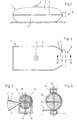
- the bag-shaped, flexible container 1 shown in FIGS. 1 and 2 consists of an upper part 2 and a lower part 3, which on their two longitudinal sides and on one end face are joined to form a common edge 5, for example glued or welded to one another.
- the upper part 2 is provided with a filling opening 4.
- the second end face of the container 1 serves as a container opening 7, which opens into a neck 6.
- the container opening 7 is closed by a closure 8.
- the neck 6 When the container 1 is closed, the neck 6 is guided through a winding rod 10 provided with a slot 9 in the middle and then wound tightly and without folds by at least 360 ° in the embodiment shown in FIG. 3 by rotating the winding rod 10 in the direction toward the center of the container .
- the layers of the container opening 7 can also overlap by repeated turning.
- the neck 6, as can be seen in FIG. 3, is deflected at several points.
- the rotation achieved can be fixed by tightening clamping screws 13, which are suitably provided near the ends of the winding rod 10.
- the clamping screws 13 lead through a clamping device 11 forming clamping element 12 with a U-profile and through the winding rod 10 and are z. B. tightened by a mother.
- the fixing element has the shape of two rectangular tubes 14, which are connected with tensioning screws 15, which lead through the winding rod 10 outside the area of the slot 9.
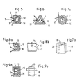
- FIG. 5 to 9 show further embodiments of the closure 8, which differ in particular by the fixing element.
- the flattened container opening 7 of the empty container 1 is in turn pushed into the slot 9 of the winding rod 10, the edge of the container opening 7 coming to rest within the winding rod 10.
- a sleeve 16 with a longitudinal slot 21 is pushed onto the winding rod 10 in the axial direction by firmly gripping the wound container opening 7.
- the longitudinal slot 21 of this sleeve 16 comes with its two longitudinal edges on the upper part 2 and the lower part 3 of the container 1 to the plant.
- both the winding rod 10 and the sleeve 16 have a rectangular profile cross section, so that both parts are non-rotatably fixed to each other. In this way, the container opening 7 is closed, the pushed-on sleeve 16 ensuring that the container opening 7 no longer detaches from the winding rod 10.
- the profile cross sections of both the winding bars 10 and the sleeve 16 are triangular.
- the two parts are fixed in a non-rotatable manner.
- the winding rod 10 and the sleeve 16 have a round profile cross section, so that an additional anti-rotation device must be provided in this embodiment.
- Fig. 7b The end of the sleeve 16 is provided with a notch 20, in which, after the sleeve 16 has been pushed on, a pin 19 arranged at the corresponding end of the winding rod 10 and extending in the radial direction engages as an anti-rotation device.
- the longitudinal slot 21 in the sleeve 16 can also serve as the notch 20. In this case, the longitudinal slot 21 also serves as a guide for pushing on the sleeve 16.
- the sleeve 16 has a U-shaped profile cross section and is pushed on transversely to the axial direction of the winding rod 10, that is to say from the right in the drawing.
- an additional locking device is provided.
- Fig. 8b is a bar 17 rotatably arranged on the sleeve 16, which is in the dashed position before and during the sliding of the sleeve 16 on the winding rod 10. After being pushed on, the bolt 17 is rotated downward and thus prevents the sleeve 16 from coming loose.
- Fig. 9a and 9b in which a clip-like ring 18 is pushed onto each of the ends of the sleeve 16.
- the container 1 is bag-shaped, so that only one closure 8 is required.
- the volume of the container 1 can thus be reduced to a certain volume from two sides.
Description
Die Erfindung betrifft einen Verschluß für flexible Behälter aus schlauch- oder sackförmigen Halbzeugen zum Transportieren und Lagern von fließ- oder schüttfähigen Gütern, mit einer Klemmvorrichtung aus mehreren Stäben, die gegeneinander festlegbar sind und einer am Umfang eines Wickelstabes angeordneten Abwickelsicherung für die zu verschließende Behälteröffnung, die insbesondere einen Stab aufweist.The invention relates to a closure for flexible containers made of tubular or sack-shaped semifinished products for transporting and storing flowable or pourable goods, with a clamping device comprising a plurality of bars which can be fixed against one another and an unwinding device arranged on the circumference of a winding rod for the container opening to be closed, which in particular has a rod.
Derartige Behälter haben beispielsweise ein Volumen von 1000 I oder 2000 I und sind vornehmlich für den Einsatz in Katastrophenfällen gedacht. Dabei können sie beispielsweise der Versorgung der Bevölkerung mit Trinkwasser dienen. Sie eignen sich aber auch beispielsweise zur Lagerung von Trinkwasser oder Abwasser auf Schiffen oder zur Vorratshaltung anderer Flüssigkeiten. Der Transport der Behälter erfolgt in der Regel mit Lastwagen, deren zulässiges Gesamtgewicht nicht überschritten werden darf. Infolgedessen kann es beim Einsatz kleinerer Lastwegen erforderlich sein, den Behälter nicht ganz zu füllen. In diesem Falle können aber während der Fahrt dynamische Massenkräfte der Flüssigkeit das Fahrzeug in Gefahr bringen, so daß ein Verschluß erforderlich ist, der das freie Volumen verringert bzw. völlig beseitigt.Such containers have a volume of 1000 l or 2000 l, for example, and are primarily intended for use in the event of a disaster. For example, they can be used to supply the population with drinking water. However, they are also suitable, for example, for storing drinking water or waste water on ships or for storing other liquids. The containers are generally transported by truck, the permissible total weight of which must not be exceeded. As a result, when using smaller load paths, it may be necessary not to fill the container completely. In this case, however, dynamic inertial forces of the liquid can endanger the vehicle while driving, so that a closure is required which reduces or completely eliminates the free volume.
Es ist weiter erforderlich, gerade für den schnellen Einsatz in Katastrophenfällen den Verschluß möglichst einfach in der Handhabung zu gestalten. Schließlich kann in manchen Fällen eine möglichst raumsparende Ausgestaltung des verschlusses erforderlich sein, um beispielsweise ein Stapeln mehrerer Behälter zu ermöglichen.It is also necessary to make the closure as easy to use as possible, especially for rapid use in the event of a disaster. Finally, in some cases it may be necessary to design the closure to be as space-saving as possible, for example to enable stacking of several containers.
Ein für diese Zwecke geeigneter Verschluß ist beispielsweise aus der DE-OS 30 04 884 bekannt. Der in dieser Druckschrift beschriebene Verschluß besteht aus in seitlichen Haltern übereinander angeordneten Klemmkörpern, durch deren Trennfugen ein Ende des Halbzeuges hindurchgeführt wird. Die Klemmkörper sind gegeneinander verschiebbar angeordnet und mit je einer in jeden Halter einsetzbaren Klemmvorrichtung gegeneinander verspannbar. Ein Nachteil dieses bekannten Verschlusses ist durch den Aufbau aus relativ vielen Einzelteilen gegeben, die seine Handhabung erschweren und die Störanfälligkeit vergrößern. Ferner ist dieser Verschluß in seinen Abmessungen relativ groß, so daß ein Stapeln mehrerer Behälter übereinander stark behindert wird. Besonders nachteilig machen sich die Abmessungen des Verschlusses bei Behältern mit geringem Fassungsvermögen bemerkbar.A closure suitable for this purpose is known for example from DE-OS 30 04 884. The closure described in this document consists of clamping bodies arranged one above the other in side holders, through the separating joints of which one end of the semifinished product is passed. The clamping bodies are arranged to be displaceable relative to one another and can be braced against one another with a clamping device that can be inserted into each holder. A disadvantage of this known closure is given by the construction of a relatively large number of individual parts, which complicate its handling and increase the susceptibility to faults. Furthermore, the dimensions of this closure are relatively large, so that stacking of several containers on top of one another is severely hindered. The dimensions of the closure are particularly disadvantageous for containers with a small capacity.
Der eingangs genannte Verschluß ist aus der FR-PS 1 458 178 bekannt. Dieser Verschluß besitzt einen Wickelstab, um den herum die zu verschließende Behälteröffnung des Behälters gewickelt wird, wobei zusätzlich nach dem Umwickeln seitlich ein Klemmkörper angelegt wird. Um ein Abwickeln der auf den Wickelstab aufgewickelten Behälteröffnung zu verhindern, ist eine Abwickelsicherung in Form eines Klammerelements auf den Wickelstab aufgeschoben. Ein entsprechender Verschluß ist aus der FR-PS 78 061 bekannt.The closure mentioned above is known from FR-
Ein Nachteil dieses bekannten Verschlusses ist ebenfalls der Aufbau aus relativ vielen Einzelteilen, die seine Handhabung erschweren und die Störanfälligkeit vergrößern. Ein wesentlicher Nachteil ist, daß mit dem bekannten Wickelstab die zu verschließende Behälteröffnung nur schwer und mit Mühe aufgewickelt werden kann, wobei insbesondere darauf geachtet werden muß, daß ein schräges Aufwickeln vermieden wird. Darüberhinaus ist die Dichtwirkung beim Aufwickeln auf den bekannten Wickelstab nicht immer gewährleistet, wobei insbesondere bei hohem Innendruck im Behälter Undichtigkeiten auftreten können. Auch ist die bekannte Abwickelsicherung nicht in der Lage, diesen Nachteilen entgegenzuwirken, die im übrigen beim bekannten Wickelstab nur sehr schwer handhabbar ist.A disadvantage of this known closure is also the construction of a relatively large number of individual parts, which complicate its handling and increase the susceptibility to faults. A major disadvantage is that with the known winding rod, the container opening to be closed can be wound up only with difficulty and with difficulty, special care being taken to avoid oblique winding. In addition, the sealing effect when winding onto the known winding rod is not always guaranteed, and leaks can occur in the container, in particular if the internal pressure is high. The known unwinding protection is also not able to counteract these disadvantages, which, moreover, is very difficult to handle with the known winding rod.
Davon ausgehend liegt der Erfindung die Aufgabe zugrunde, einen verbesserten Verschluß zu schaffen, der das Aufwickeln der zu verschließenden Behälteröffnung erleichtert und der jederzeit einwandfreie Dichteigenschaften auch bei hohem Innendruck im Behälter gewährleistet.Proceeding from this, the object of the invention is to provide an improved closure which facilitates the winding of the container opening to be closed and which ensures perfect sealing properties at all times, even with high internal pressure in the container.
Als technische Lösung für diese Aufgabe wird mit der Erfindung vorgeschlagen, daß der Wickelstab einen Schlitz aufweist, so daß ein Oberteil und ein Unterteil des Behälters in den Schlitz einschiebbar und unter mindestens zweimaligem Umlenken um die durch den Schlitz gebildeten Kanten des Wickelstabes um mindestens 270° stramm und faltenlos einwickelbar sind.As a technical solution to this problem it is proposed with the invention that the winding rod has a slot so that an upper part and a lower part of the container can be inserted into the slot and with at least two deflections around the edges of the winding rod formed by the slot by at least 270 ° are tight and wrinkle-free.
Der Vorteil dieses Verschlusses liegt darin, daß durch den Schliz im Wickelstab das Aufwickeln der zu vorschließenden Behälteröffnung erleichtert wird. Zum Aufwickeln braucht die Behälteröffnung lediglich in den Schlitz eingeschoben werden, wobei bereits bei einer Umdrehung des Wickelstabes um 90° ein Verrutschen der Behälteröffnung auf dem Wickelstab nicht mehr eintreten kann. Insbesondere ist es mit dem Schlitz sehr einfach, die Behälteröffnung mehrmals um den Wickelstab aufzurollen, wenn ein geringeres Volumen im Behälter benötigt wird. Ein weiterer Vorteil liegt darin, daß durch den Schlitz eine Klemmkante gebildet wird, die den Behälter einwandfrei auch bei hohem Innendruck abdichtet. Schließlich besteht der Verschluß nur aus wenigen Teilen und ist damit kaum störanfällig. Darüberhinaus weist er im Vergleich zu den bekannten Varschlüssen ein wesentlich geringeres Gewicht auf.The advantage of this closure is that the wrap in the winding rod makes it easier to wind up the container opening to be closed. For winding up, the container opening only needs to be pushed into the slot, and the container opening can no longer slip on the winding rod when the winding rod is rotated by 90 °. In particular, it is very easy with the slot to roll up the container opening several times around the winding rod if a smaller volume is required in the container. Another advantage is that the slot forms a clamping edge that seals the container perfectly even at high internal pressures. Finally, the closure consists of only a few parts and is therefore hardly susceptible to failure. In addition, it has a significantly lower weight compared to the known var closures.
Gemäß einem weiteren Merkmal der Erfindung ist die Abwickelsicherung durch ein stabförmiges Spannelement gebildet, das mittels Spannschrauben mit dem Wickelstab verbunden ist. Dabei kann das Spannelement als Schiene mit U-förmigem Profil ausgebildet sein, die den geschlitzten Wickelstab teilweise oder vollständig aufnimmt. Diese Ausführungsform bringt den Vorteil mit sich, daß an zwei Kanten des U-förmigen Profiles zusätzlich Ober- und Unterteil des zu verschließenden flexiblen Behälters gegen den geschlitzten Wickelstab gequetscht wird und somit zusätzliche Abdichtungen des Verschlusses gegeben sind.According to a further feature of the invention, the unwind protection is formed by a rod-shaped tensioning element which is connected to the winding bar by means of tensioning screws. The clamping element can be designed as a rail with a U-shaped profile, the slotted winding rod partially or completely. This embodiment has the advantage that the upper and lower part of the flexible container to be closed is additionally squeezed against the slotted winding rod on two edges of the U-shaped profile and thus additional seals of the closure are provided.
Die Abwickelsicherung kann auch durch zwei einander gegenüberliegende Rechteckrohr oder Profilstangen gebildet sein, die mit durch den geschlitzten Wickelstab führenden Spannschrauben außerhalb der Schlitzlänge des Wickelstabs untereinander verbunden sind.The unwind protection can also be formed by two opposing rectangular tubes or profiled rods which are connected to one another by means of tensioning screws leading through the slotted winding rod outside the slot length of the winding rod.
In einer weiteren Ausführungsform ist die Abwickelsicherung durch eine die aufgewickelte Behälteröffnung fest umgreifende, auf den Wickelstab aufschiebbare Hülse gebildet, die im aufgeschobenen Zustand gegenüber dem Wickelstab unverdrehbar festgelegt ist.In a further embodiment, the unwinding protection is formed by a sleeve which firmly encompasses the wound container opening and can be pushed onto the winding rod and which, in the pushed-on state, is fixed non-rotatably with respect to the winding rod.
Durch die Ausbildung der Abwickelsicherung als Hülse wird eine schnelle und zuverlässige Fixierung der auf dem Wickelstab aufgewickelten Behälteröffnung erreicht. Zusätzliche Elemente, wie z.B. Spannschrauben, die bei geöffnetem Verschluß und während der Reinigung des Behälters verlorengehen können, werden nicht benötigt. Die Hülse kann in Axialrichtung des Wickelstabs auf diese geschoben werden. Da sie im aufgeschobenen Zustand unverdrehbar festgelegt ist, kenn sich die aufgewickelte Behälteröffnung nicht von alleine lösen, so daß jederzeit der Behälter einwandfrei geschlossen ist. Die Handhabung des Verschlusses ist noch mehr erleichtert und die Störanfälligkeit verringert.By designing the unwinding protection as a sleeve, a quick and reliable fixation of the container opening wound on the winding rod is achieved. Additional elements such as Tensioning screws, which can be lost when the closure is open and during cleaning of the container, are not required. The sleeve can be pushed onto the winding rod in the axial direction. Since it is fixed so that it cannot be rotated when it is pushed open, the wound-up container opening does not come loose on its own, so that the container is closed properly at all times. The handling of the closure is even easier and the susceptibility to faults is reduced.
Bei einer bevorzugten Ausführungsform ist die Hülse auf dem Wickelstab infolge eines von der Kreisform abweichenden Profilquerschnittes sowohl der Hülse als auch des Wickelstabs unverdrehbar gehalten. Der Profilquerschnitt der Hülse und der Profilquerschnitt des Wickelstabs kann dabei rechteckig, insbesondere quadratisch, oder oval sein. Durch diese besondere Gestaltung der Profilquerschnitte kann auf eine zusätzliche Verdrehsicherung verzichtet werden.In a preferred embodiment, the sleeve on the winding rod is held non-rotatably as a result of a profile cross section of both the sleeve and the winding rod that deviates from the circular shape. The profile cross section of the sleeve and the profile cross section of the winding rod can be rectangular, in particular square, or oval. This special design of the profile cross-sections means that there is no need for an additional anti-rotation lock.
In einer anderen Ausführungsform ist die Hülse auf dem Wickelstab durch in beide Teile eingreifende Verdrehsicherungen unverdrehbar gehalten. Zu diesem Zweck kann das Ende der Hülse mit einer Einkerbung versehen sein, in die nach Aufschieben der Hülse ein am entsprechenden Ende des Wickelstabs angeordneter, sich in radialer Richtung erstreckender Zapfen als Verdrehsicherung eingreift. Mit dieser Ausführungsform wird die Möglichkeit eröffnet, auch Wickelstäbe und Hülsen mit einem runden Querschnitt zu verwenden. In einer bevorzugten Weiterbildung dient der Längsschlits zugleich als Einkerbung, wobei Vorzugsweise dieser an beiden Enden der Hülse zur Aufnahme von jeweils einem, an den beiden Enden des Wickelstabs angeordneten Zapfen dient. Neben dem Verzicht auf eine zusätzliche Einkerbung in der Hülse dient der Längsschlitz zusammen mit den Zapfen als Führung für das Aufschieben der Hülse auf den Wickelstab. Dadurch wird vermieden, daß sich während des Aufschiebens der Hülse diese gegenüber dem Wickelstab verdreht.In another embodiment, the sleeve is held non-rotatably on the winding bar by means of anti-rotation devices engaging in both parts. For this purpose, the end of the sleeve can be provided with a notch into which, after the sleeve has been pushed open, a pin arranged at the corresponding end of the winding rod and extending in the radial direction engages as a rotation lock. This embodiment opens up the possibility of also using winding rods and sleeves with a round cross section. In a preferred development, the longitudinal slide also serves as a notch, this preferably being used at both ends of the sleeve for receiving one pin each, which is arranged at the two ends of the winding rod. In addition to dispensing with an additional notch in the sleeve, the longitudinal slot together with the pins serves as a guide for pushing the sleeve onto the winding rod. This prevents the sleeve from twisting relative to the winding bar during the sliding on.
Gemäß einem weiteren Merkmal der Erfindung besteht die Hülse aus einem elastischen Material und steht im Reibungsverbund mit der Außenseite der aufgewickelten Behälteröffnung. Vorzugsweise ist die Höhe des Längsschlitzes etwas geringer als die Höhe der flachgelegten Behälteröffnung, wobei die Längskanten des Längsschlitzes der Hülse nach dem Aufschieben am Ober- und Unterteil des Behälters anliegen. Ein unbeabsichtigtes Verschieben der Hülse im aufgeschobenen Zustand gegenüber dem Wickelstab wird damit erschwert.According to a further feature of the invention, the sleeve consists of an elastic material and is in frictional connection with the outside of the wound-up container opening. The height of the longitudinal slot is preferably somewhat less than the height of the flattened container opening, the longitudinal edges of the longitudinal slot of the sleeve abutting the upper and lower part of the container after being pushed open. This makes it difficult to inadvertently move the sleeve in the pushed-open state relative to the winding rod.
Gemäß einem weiteren Merkmal der Erfindung ist die der stirnseitigen Eintrittsöffnung der Hülse gegenüberliegende Öffnung von einer Platte verschlossen. Diese Platte dient als Anschlag, wodurch ein einfaches Positionieren beim Aufschieben der Hülse auf den Wickelstab in axialer Richtung sichergestellt ist.According to a further feature of the invention, the opening opposite the front entry opening of the sleeve is closed by a plate. This plate serves as a stop, which ensures easy positioning in the axial direction when the sleeve is pushed onto the winding rod.
Zur Weiterbildung des erfindungsgemäßen Verschlusses wird vorgeschlagen, daß zwei, auf . die beiden Enden des Wickelstabs aufschiebbare Hülsen vorgesehen sind, deren jeweilige Länge kleiner als die hälfte der Gesamtlänge des Wickelstabs ist. Dadurch vereinfacht sich die fixierung der auf dem Wickelstab aufgewickelten Behälteröffnung, da nicht eine der Gesamtlänge des Wickelstabs entsprechende Hülse aufgeschoben werden muß, sondern lediglich zwei kleine Hülsen, die auf die beiden Enden des Wickelstabs aufgeschoben werden. Dies ist insbesondere bei breiten Behälteröffnungen von Vorteil, wenn infolge der Länge der Hülse beim Aufschieben ein großer Reibungswiderstand auftritt.To further develop the closure according to the invention it is proposed that two,. the two ends of the winding rod are slidable sleeves, the length of which is less than half the total length of the winding rod. This simplifies the fixing of the container opening wound on the winding rod, since it is not necessary to slide on a sleeve corresponding to the total length of the winding rod, but only two small sleeves which are pushed onto the two ends of the winding rod. This is particularly advantageous with wide container openings if, due to the length of the sleeve, a large frictional resistance occurs when pushed on.
In einer weiteren Ausführungsform weist die Hülse einen U-förmigen Profilquerschnitt auf und ist quer zur Axialrichtung des Wickelstabs aufschiebbar, wobei an den beiden Enden der Hülse eine Verschiebesicherung angeordnet ist. Als Verschiebesicherung kann ein an der Hülse angelankter, drehbarer, den Wickelstab hintergreifender Riegel vorgesehen sein.In a further embodiment, the sleeve has a U-shaped profile cross section and can be pushed on transversely to the axial direction of the winding rod, with a displacement lock being arranged at the two ends of the sleeve. A locking bolt that is anchored to the sleeve and rotatable and engages behind the winding bar can be provided to prevent displacement.
Als Verschiebeeinrichtung ist auch ein auf das Ende aufschiebbarer Ring denkbar. Die U-förmige Hülse kommt dann zur Anwendung, wenn breite Behälteröffnungen verschlossen werden müssen, was bei einer axialen Verschiebung der Hülse zu einem hohen Reibungswiderstand führen würde.A ring that can be pushed onto the end is also conceivable as a displacement device. The U-shaped sleeve is used when wide container openings have to be closed, which would lead to high frictional resistance if the sleeve were moved axially.
Schließlich wird mit der Erfindung vorgeschlagen, daß der in den Schlitz des Wickelstabs ragende Rand der Behälteröffnung innerhalb das Wickelstabs angeordnet ist. Es werden dadurch störende Erhebungen der aufgewickelten Behälteröffnung vermieden, die ein Aufschieben der Hülse erschweren, wenn nicht gar unmöglich machen.Finally, it is proposed with the invention that the edge of the container opening protruding into the slot of the winding rod is arranged within the winding rod. This avoids disturbing elevations of the wound container opening, which make it difficult, if not impossible, to slide the sleeve open.
In den Zeichnungen sind Ausführungsformen des erfindungemäßen Verschlusses dargestellt, und zwar zeigen:
- Fig. 1 einen gefüllten, flexiblen Behälter mit Verschluß in Seitenansicht;
- Fig. 2 eine Draufsicht auf den Behälter nach Fig. 1;
- Fig. 3 den Verschlug entlang der Linie A-A in Fig. 2 geschnitten in einer ersten Ausführungsform mit einem Spannelement;
- Fig. 4 den Verschluß entlang der Linie A-A in Fig. 2 geschnitten in einer zweiten Ausführungsform mit einem Rechteckrohr;
- Fig. 5 den Verschluß entlang der Linie A-A in Fig. 2 geschnitten in einer dritten Ausführungsform mit einer Hülse und mit quadratischem Profilquerschnitt;
- Fig. 6 den Verschluß entlang der Linie A-A in Fig. 2 geschnitten in einer vierten Ausführungsform mit einer Hülse und mit dreieckigem Profilquerschnitt;
- Fig. 7a den Verschluß entlang der Linie A-A in Fig. 2 geschnitten in einer fünften Ausführungsform mit einer Hülse und mit rundem Profilquarschnitt;
- Fig. 7b den Verschluß nach Fig. 7a in Draufsicht im Endbereich mit einer Verdrehsicherung;
- Fig. 8a den Verschluß entlang der Linie A-A in Fig. 2 geschnitten in einer sechsten Ausführungsform mit einer U-förmigen Hülse;
- Fig. 8b den Verschluß nach Fig. 8a mit einem Riegel als Verschiebesicherung in Längssicht;
- Fig. 9a den Verschluß entlang der Linie A-A in Fig. 2 geschnitten in einer der Fig. 8a entsprechenden Ausführungsform, jedoch mit einem Ring als Verschiebesicherung;
- Fig. 9b den Verschluß nach Fig. 9a in Draufsicht mit dem auf das Ende aufgeschobenen Ring.
- Figure 1 shows a filled, flexible container with closure in side view.
- Fig. 2 is a plan view of the container of Fig. 1;
- 3 shows the closure along the line AA in FIG. 2 in a first embodiment with a tensioning element;
- 4 shows the closure along the line AA in FIG. 2 cut in a second embodiment with a rectangular tube;
- 5 shows the closure along the line AA in FIG. 2 cut in a third embodiment with a sleeve and with a square profile cross section;
- 6 shows the closure along the line AA in FIG. 2 cut in a fourth embodiment with a sleeve and with a triangular profile cross section;
- 7a shows the closure along the line AA in FIG. 2 in a fifth embodiment with a sleeve and with a round profile section;
- 7b shows the closure according to FIG. 7a in a top view in the end region with an anti-rotation device;
- 8a shows the closure along the line AA in FIG. 2 cut in a sixth embodiment with a U-shaped sleeve;
- FIG. 8b the closure according to FIG. 8a with a bolt as securing against displacement in a longitudinal view;
- 9a shows the closure along the line AA in FIG. 2 cut in an embodiment corresponding to FIG. 8a, but with a ring as a securing means against displacement;
- Fig. 9b the closure of Fig. 9a in plan view with the ring pushed onto the end.
Der in den Fig. 1 und 2 dargestellte sackförmige, flexible Behälter 1 besteht aus einem Oberteil 2 und einem Unterteil 3, die an ihren beiden Längsseiten und an einer Stirnseite zu einem gemeinsamen Rand 5 zusammengenfügt, beispielsweise miteinender verklebt oder verschweißt sind. Das Oberteil 2 ist mit einer Einfüllöffnung 4 versehen. Die zweite Stirnseite des Behälters 1 dient als Behälteröffnung 7, die in einem Hals 6 mündet. Die Behälteröffnung 7 ist durch einen Verschluß 8 verschlossen.The bag-shaped,
Der Hals 6 wird beim Verschließen des Behälters 1 durch einen in der Mitte mit einem Schlitz 9 versehanen Wickelstab 10 geführt und dann durch Drehen des Wickelstabs 10 in Richtung zur Behältermitte bei der in Fig, 3 dargestellten Ausführungsform um mindestens 360° möglichst stramm und faltanlos aufgewickelt. Durch mehrmaliges Drehen können sich die Lagen der Behälter-öffnung 7 auch überlappen. Dabei wird der Hals 6, wie der Fig. 3 zu entnehmen ist, an mehreren Stellen umgelenkt. Sobald die gewünschte Aufwicklung erforgt ist, kann die erreichte Umdrehung durch Anziehen von Spannschrauben 13, welche in geeigneter Weise nahe den Enden das Wickelstabs 10 vorgesehen sind, fixiert werden. Die Spannschrauben 13 führen durch ein eine Klemmvorrichtung 11 bildendes Spannelement 12 mit U-Profil und durch den Wickelstab 10 und werden z. B. durch eine Mutter festgezogen.When the
Bei der in Fig. 4 dargestellten Ausführungsform der Erfindung erfolgt ein Einwickeln um mindestens 270°. Hier hat das Fixierelement die Form zweier Rechteckrohre 14, die mit Spannschrauben 15 verbunden sind, die durch den Wickelstab 10 außerhalb des Bereiches des Schlitzes 9 führen.In the embodiment of the invention shown in FIG. 4, it is wrapped by at least 270 °. Here, the fixing element has the shape of two
In den Fig. 5 bis 9 sind weitere Ausführungsformen des Verschlusses 8 dargestellt, die sich insbesondere durch das Fixierelement unterscheiden. Die flachgelegte Behälteröffnung 7 das leeren Behälters 1 wird wiederum in den Schlitz 9 des Wickelstabs 10 eingeschoben, wobei der Rand der Behälteröffnung 7 innerhalb das Wickelstabs 10 zum Liegen kommt.5 to 9 show further embodiments of the
Zur Fixierung der auf dem Wickelstab 10 aufgewickelten Behälteröffnung 7 wird in den Ausführungsformen gemäß den Fig. 5 bis 9 eine Hülse 16 mit einem Längsschlitz 21 in axialer Richtung auf den Wickelstab 10 aufgeschoben, indem sie die aufgewickelte Behälteröffnung 7 fest umgreift. Der Längsschlitz 21 dieser Hülse 16 kommt dabei mit seinen beiden Längskanten am Oberteil 2 und am Unterteil 3 des Behälters 1 zur Anlage. In Fig. 5 weist sowohl der Wickelstab 10 als auch die Hülse 16 einen rechteckigen Profilquerschnitt auf, so daß beide Teile unverdrehbar zueinander festgelegt sind. Auf diese Weise ist die Behälteröffnung 7 verschlossen, wobei die aufgeschobene Hülse 16 gewährleistet, daß sich die Behälteröfnung 7 nicht mehr von dem Wickelstab 10 löst.In order to fix the
Bei der Ausführungsform in Form. 6 sind die Profilquerschnitte sowohl die Wickelstabs 10 als auch der Hülse 16 dreieckig. Auch hier sind die beiden Teile unverdrehbar festgelegt.In the embodiment in shape. 6, the profile cross sections of both the winding
Bei der in Fig. 7a dargestellten Ausführungsform des Verschlusses 8 weisen der Wickelstab 10 und die Hülse 16 einen runden Profilquerschnitt auf, so daß bei dieser Ausführungsform eine zusätzliche Verdrehsicherung vorgesehen sein muß. Diese ist in Fig. 7b dargestellt. Das Ende der Hülse 16 ist mit einer Einkerbung 20 vorsehen, in die nach Aufschieben der Hülse 16 ein am entsprechenden Ende des Wickelstabs 10 angeordneter Zapfen 19, der sich in radialer Richtung erstreckt, als Verdrehsicherung eingreift. Als einkerbung 20 kann auch der Längsschlitz 21 in der Hülse 16 dienen. In diesem Fall dient der Längsschlitz 21 zusätzlich als Führung für das Aufschieben der Hülse 16.In the embodiment of the
Bei der in Fig. 8 und 9 dargestellten Ausführungsform des Verschlusses 8 weist die Hülse 16 einen U-förmigen Profilquerschnitt auf und wird quer zur Axialrichtung des Wickelstabs 10 aufgeschoben, also in der Zeichnung von rechts. Um zu vorhindern, daß die Hülse 16 von der auf dem Wickelstab 10 gewickelten Behälteröffnung 7 abrutscht, ist eine zusätzliche Verschiebesicherung vorgesehen. Zu diesem Zweck ist in Fig: 8b ein Riegel 17 an der Hülse 16 drehbar angeordnet, der sich vor und während des Aufschiebens der Hülse 16 auf dem Wickelstab 10 in der gestrichelten Position befindet. Nach dem Aufschieben wird der Riegel 17 nach unten gedreht und verhindert somit, das sich die Hülse 16 löst. Eine andere Möglichkeit ist in Fig. 9a und 9b dargestellt, bei der auf jedes der Enden der Hülse 16 ein klammerartiger Ring 18 aufgeschoben wird.In the embodiment of the
In den dargestellten Ausführungsbeispielen ist der Behälter 1 sackförmig ausgebildet, so daß nur ein Verschluß 8 benötigt wird. Es ist aber auch möglich, als Behälter 1 ein an beiden Enden offenes schlauchförmiges Halbzeug zu verwenden, wobei dann zwei Verschlüsse 8 erforderlich sind. Damit kann das Volumen des Behälters 1 von zwei Seiten her auf ein bestimmtes Volumen verringert werden.

Claims (21)
Priority Applications (2)
| Application Number | Priority Date | Filing Date | Title |
|---|---|---|---|
| AT83105613T ATE19498T1 (en) | 1982-07-09 | 1983-06-08 | CLOSURE FOR FLEXIBLE CONTAINERS. |
| KE378287A KE3782A (en) | 1982-07-09 | 1987-10-23 | Closure device for flexible containers |
Applications Claiming Priority (4)
| Application Number | Priority Date | Filing Date | Title |
|---|---|---|---|
| DE3225681 | 1982-07-09 | ||
| DE3225681A DE3225681C1 (en) | 1982-07-09 | 1982-07-09 | Closure for flexible containers |
| DE19833313004 DE3313004A1 (en) | 1983-04-12 | 1983-04-12 | Closure for flexible containers |
| DE3313004 | 1983-04-12 |
Publications (3)
| Publication Number | Publication Date |
|---|---|
| EP0098973A2 EP0098973A2 (en) | 1984-01-25 |
| EP0098973A3 EP0098973A3 (en) | 1984-06-06 |
| EP0098973B1 true EP0098973B1 (en) | 1986-04-30 |
Family
ID=25802935
Family Applications (1)
| Application Number | Title | Priority Date | Filing Date |
|---|---|---|---|
| EP83105613A Expired EP0098973B1 (en) | 1982-07-09 | 1983-06-08 | Closure device for flexible containers |
Country Status (20)
| Country | Link |
|---|---|
| EP (1) | EP0098973B1 (en) |
| AU (1) | AU563947B2 (en) |
| BR (1) | BR8303680A (en) |
| CA (1) | CA1222728A (en) |
| CS (1) | CS253576B2 (en) |
| DD (1) | DD210007A5 (en) |
| DE (1) | DE3363264D1 (en) |
| DK (1) | DK154131C (en) |
| EG (1) | EG15961A (en) |
| ES (3) | ES281456Y (en) |
| FI (1) | FI76983C (en) |
| GR (1) | GR77504B (en) |
| HU (1) | HU186720B (en) |
| IL (1) | IL69120A (en) |
| MX (1) | MX158907A (en) |
| NO (1) | NO162806C (en) |
| PT (1) | PT76947B (en) |
| RO (1) | RO88372A (en) |
| TR (1) | TR21547A (en) |
| YU (1) | YU43318B (en) |
Cited By (1)
| Publication number | Priority date | Publication date | Assignee | Title |
|---|---|---|---|---|
| DE29609802U1 (en) * | 1996-06-03 | 1996-08-14 | Pro Pack Handels Und Vertriebs | Bag closure |
Families Citing this family (2)
| Publication number | Priority date | Publication date | Assignee | Title |
|---|---|---|---|---|
| DE3500803A1 (en) * | 1985-01-11 | 1986-07-17 | Pietro Crema Cremona Mariani | Apparatus for the vacuum packaging of foodstuffs and other articles |
| DE3830630A1 (en) * | 1988-09-09 | 1990-03-15 | Fresenius Ag | Multiple chamber bag system |
Family Cites Families (5)
| Publication number | Priority date | Publication date | Assignee | Title |
|---|---|---|---|---|
| FR1229670A (en) * | 1958-10-13 | 1960-09-08 | Collapsible container for the transport of liquid, pasty or granular products | |
| US3141221A (en) * | 1962-11-13 | 1964-07-21 | Amtec Inc | Closure for flexible bags |
| FR1458178A (en) * | 1965-05-17 | 1966-11-10 | Improvement of closures, of the waterproof type, for reservoirs and flexible tubular bags | |
| US3481007A (en) * | 1968-04-29 | 1969-12-02 | Nathan Scarritt Jr | Watertight closure for plastic bags |
| DE2239097C3 (en) * | 1972-08-09 | 1978-03-02 | Kurt Dipl.-Ing. 5485 Sinzig Kronenberg | Closure for flexible containers |
-
1983
- 1983-06-08 DE DE8383105613T patent/DE3363264D1/en not_active Expired
- 1983-06-08 EP EP83105613A patent/EP0098973B1/en not_active Expired
- 1983-06-10 FI FI832102A patent/FI76983C/en not_active IP Right Cessation
- 1983-06-14 GR GR71663A patent/GR77504B/el unknown
- 1983-06-21 EG EG378/83A patent/EG15961A/en active
- 1983-06-28 PT PT76947A patent/PT76947B/en unknown
- 1983-06-28 RO RO83111437A patent/RO88372A/en unknown
- 1983-06-29 TR TR21547A patent/TR21547A/en unknown
- 1983-06-30 IL IL69120A patent/IL69120A/en not_active IP Right Cessation
- 1983-07-04 MX MX197928A patent/MX158907A/en unknown
- 1983-07-05 YU YU1453/83A patent/YU43318B/en unknown
- 1983-07-06 AU AU16608/83A patent/AU563947B2/en not_active Ceased
- 1983-07-07 ES ES1983281456U patent/ES281456Y/en not_active Expired
- 1983-07-07 NO NO832494A patent/NO162806C/en unknown
- 1983-07-07 DK DK315183A patent/DK154131C/en not_active IP Right Cessation
- 1983-07-07 CS CS835159A patent/CS253576B2/en unknown
- 1983-07-08 HU HU832457A patent/HU186720B/en unknown
- 1983-07-08 BR BR8303680A patent/BR8303680A/en not_active IP Right Cessation
- 1983-07-08 CA CA000432085A patent/CA1222728A/en not_active Expired
- 1983-07-11 DD DD83252968A patent/DD210007A5/en unknown
-
1985
- 1985-02-15 ES ES1985284659U patent/ES284659Y/en not_active Expired
- 1985-02-15 ES ES1985284658U patent/ES284658Y/en not_active Expired
Cited By (1)
| Publication number | Priority date | Publication date | Assignee | Title |
|---|---|---|---|---|
| DE29609802U1 (en) * | 1996-06-03 | 1996-08-14 | Pro Pack Handels Und Vertriebs | Bag closure |
Also Published As
Similar Documents
| Publication | Publication Date | Title |
|---|---|---|
| DE60008032T2 (en) | Containers with foldable walls | |
| DE2303240A1 (en) | RECEPTION CONTAINER FOR ROLLED TRACKS | |
| DE2758976A1 (en) | CONTAINER FOR RECEIVING AND DISPENSING A FILLING MATERIAL FREE OF DRINK AND PROCESS FOR FILLING SUCH A CONTAINER | |
| DE2810564C3 (en) | Folding cover for several items arranged in rows | |
| DE2349370A1 (en) | SHIPPING CONTAINER | |
| WO2013050968A1 (en) | Method for draining or filling a vessel while avoiding contamination | |
| DE3312064C2 (en) | Box for storing photographic films | |
| EP0098973B1 (en) | Closure device for flexible containers | |
| DE3225681C1 (en) | Closure for flexible containers | |
| DE3119744A1 (en) | "BAG" | |
| DE4414275C2 (en) | Device for the metered removal of flowable material from a container | |
| DE3004884C2 (en) | Closure for flexible containers | |
| DE2239097C3 (en) | Closure for flexible containers | |
| DE19652132C2 (en) | Reusable tube for winding and transporting thread-like or band-shaped goods made of natural or plastic material | |
| DE2552438B1 (en) | VALVE BAG | |
| CH461351A (en) | Carrying bag | |
| DE3313004A1 (en) | Closure for flexible containers | |
| DE3223539A1 (en) | Large-size bag | |
| EP0571650B1 (en) | Knock-down table system | |
| DE3121463C2 (en) | "Sack for spillage" | |
| DE3118725A1 (en) | Device for removing flowable products from an insert bag | |
| DE3801192A1 (en) | Sack or bag with a carrying handle | |
| DE1286714B (en) | Carrying device for containers made of cardboard or the like. | |
| DE2200313A1 (en) | packaging | |
| DE3540692C2 (en) |
Legal Events
| Date | Code | Title | Description |
|---|---|---|---|
| PUAI | Public reference made under article 153(3) epc to a published international application that has entered the european phase |
Free format text: ORIGINAL CODE: 0009012 |
|
| AK | Designated contracting states |
Designated state(s): AT BE CH DE FR GB IT LI LU NL SE |
|
| PUAL | Search report despatched |
Free format text: ORIGINAL CODE: 0009013 |
|
| AK | Designated contracting states |
Designated state(s): AT BE CH DE FR GB IT LI LU NL SE |
|
| 17P | Request for examination filed |
Effective date: 19840425 |
|
| GRAA | (expected) grant |
Free format text: ORIGINAL CODE: 0009210 |
|
| AK | Designated contracting states |
Kind code of ref document: B1 Designated state(s): AT BE CH DE FR GB IT LI LU NL SE |
|
| REF | Corresponds to: |
Ref document number: 19498 Country of ref document: AT Date of ref document: 19860515 Kind code of ref document: T |
|
| REF | Corresponds to: |
Ref document number: 3363264 Country of ref document: DE Date of ref document: 19860605 |
|
| ET | Fr: translation filed | ||
| ITF | It: translation for a ep patent filed |
Owner name: ING. ZINI MARANESI & C. S.R.L. |
|
| PG25 | Lapsed in a contracting state [announced via postgrant information from national office to epo] |
Ref country code: LU Free format text: LAPSE BECAUSE OF NON-PAYMENT OF DUE FEES Effective date: 19860630 |
|
| PLBE | No opposition filed within time limit |
Free format text: ORIGINAL CODE: 0009261 |
|
| STAA | Information on the status of an ep patent application or granted ep patent |
Free format text: STATUS: NO OPPOSITION FILED WITHIN TIME LIMIT |
|
| 26N | No opposition filed | ||
| PGFP | Annual fee paid to national office [announced via postgrant information from national office to epo] |
Ref country code: NL Payment date: 19870630 Year of fee payment: 5 |
|
| PG25 | Lapsed in a contracting state [announced via postgrant information from national office to epo] |
Ref country code: BE Effective date: 19890630 |
|
| BERE | Be: lapsed |
Owner name: KRONENBERG KURT Effective date: 19890630 |
|
| PG25 | Lapsed in a contracting state [announced via postgrant information from national office to epo] |
Ref country code: NL Effective date: 19900101 |
|
| NLV4 | Nl: lapsed or anulled due to non-payment of the annual fee | ||
| PGFP | Annual fee paid to national office [announced via postgrant information from national office to epo] |
Ref country code: GB Payment date: 19910520 Year of fee payment: 9 |
|
| PGFP | Annual fee paid to national office [announced via postgrant information from national office to epo] |
Ref country code: SE Payment date: 19910619 Year of fee payment: 9 |
|
| ITTA | It: last paid annual fee | ||
| PG25 | Lapsed in a contracting state [announced via postgrant information from national office to epo] |
Ref country code: GB Effective date: 19920608 |
|
| PG25 | Lapsed in a contracting state [announced via postgrant information from national office to epo] |
Ref country code: SE Effective date: 19920609 |
|
| GBPC | Gb: european patent ceased through non-payment of renewal fee |
Effective date: 19920608 |
|
| PGFP | Annual fee paid to national office [announced via postgrant information from national office to epo] |
Ref country code: FR Payment date: 19930616 Year of fee payment: 11 |
|
| PGFP | Annual fee paid to national office [announced via postgrant information from national office to epo] |
Ref country code: AT Payment date: 19930623 Year of fee payment: 11 |
|
| PGFP | Annual fee paid to national office [announced via postgrant information from national office to epo] |
Ref country code: CH Payment date: 19930719 Year of fee payment: 11 |
|
| PGFP | Annual fee paid to national office [announced via postgrant information from national office to epo] |
Ref country code: DE Payment date: 19930812 Year of fee payment: 11 |
|
| PG25 | Lapsed in a contracting state [announced via postgrant information from national office to epo] |
Ref country code: AT Effective date: 19940608 |
|
| PG25 | Lapsed in a contracting state [announced via postgrant information from national office to epo] |
Ref country code: LI Effective date: 19940630 Ref country code: CH Effective date: 19940630 |
|
| EUG | Se: european patent has lapsed |
Ref document number: 83105613.0 Effective date: 19930109 |
|
| PG25 | Lapsed in a contracting state [announced via postgrant information from national office to epo] |
Ref country code: FR Effective date: 19950228 |
|
| REG | Reference to a national code |
Ref country code: CH Ref legal event code: PL |
|
| PG25 | Lapsed in a contracting state [announced via postgrant information from national office to epo] |
Ref country code: DE Effective date: 19950301 |
|
| REG | Reference to a national code |
Ref country code: FR Ref legal event code: ST |