EP0094469A1 - Matrix-Thermodrucker - Google Patents
Matrix-Thermodrucker Download PDFInfo
- Publication number
- EP0094469A1 EP0094469A1 EP82810190A EP82810190A EP0094469A1 EP 0094469 A1 EP0094469 A1 EP 0094469A1 EP 82810190 A EP82810190 A EP 82810190A EP 82810190 A EP82810190 A EP 82810190A EP 0094469 A1 EP0094469 A1 EP 0094469A1
- Authority
- EP
- European Patent Office
- Prior art keywords
- frame
- thermal printer
- print head
- shaft
- matrix thermal
- Prior art date
- Legal status (The legal status is an assumption and is not a legal conclusion. Google has not performed a legal analysis and makes no representation as to the accuracy of the status listed.)
- Granted
Links
Images
Classifications
-
- B—PERFORMING OPERATIONS; TRANSPORTING
- B41—PRINTING; LINING MACHINES; TYPEWRITERS; STAMPS
- B41J—TYPEWRITERS; SELECTIVE PRINTING MECHANISMS, i.e. MECHANISMS PRINTING OTHERWISE THAN FROM A FORME; CORRECTION OF TYPOGRAPHICAL ERRORS
- B41J25/00—Actions or mechanisms not otherwise provided for
- B41J25/304—Bodily-movable mechanisms for print heads or carriages movable towards or from paper surface
- B41J25/312—Bodily-movable mechanisms for print heads or carriages movable towards or from paper surface with print pressure adjustment mechanisms, e.g. pressure-on-the paper mechanisms
Definitions
- the present invention relates to a matrix thermal printer with a frame, a print head and a pressure roller rotatably mounted in the frame.
- Such printers are known.
- the text is printed line by line by means of a print head arranged transversely to the direction of the paper feed.
- the strip to be printed, paper strips or labels stuck on a carrier strip are held between the print head and a pressure roller.
- the print is made with the strip stationary.
- the print head and pressure roller must ensure good printing on the one hand and allow easy insertion of the paper strip on the other.
- the printhead must be able to be replaced periodically, since it is exposed to moderate, unavoidable wear.
- these requirements i.e. ensuring a good contact pressure, easy introduction of the strip to be printed and easy replacement of the print head, are met with technically complicated means, the costs of which are disproportionately high compared to the total production costs, since matrix thermal printers are simpler and therefore cheaper Applications are provided.
- the object on which the invention is based was to create a matrix thermal printer which has means for guiding the print head and for controlling its position, so that all three of the above-mentioned requirements can be met simply and reliably.
- the print head is pivotally and displaceably mounted with play by means of two horizontal guide wings around a pin arranged parallel to the axis of the pressure roller and fastened to the frame, and can be pressed against the pressure roller by means of a third, spring-loaded, vertical guide wing, wherein in the pressed-on position, only one of the horizontal guide wings is operatively connected to the Za p f mentioned that a shaft rotatably mounted in the frame is provided for controlling the pivoting movement of the print head.
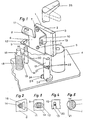
- Fig. 1 only those elements of the matrix thermal printer are shown which are necessary for understanding the invention. The electrical connections, the strip to be printed and its drive are not shown.
- the print head 1 consists of a body 2 which has a number of heatable elements 3. These elements 3 are arranged in a straight line and, when the print head 1 is in the printing position, they print on the strip (not shown) which lies between il and a generator of a pressure roller 5 rotatably mounted in the frame 4 of the matrix thermal print.
- body 2 On body 2 is a 6 fastened by means of screws 7, which has three bent wings 8, 9 and 10.
- the wing 8 has a triangular hole 11, the Wing 9 an elongated hole 12 and the wing 10 an open, downward slot 13.
- a pin 14 is fastened with a bi-conical groove 15. Furthermore, the frame 4 carries a pin 16 and a rotatably mounted shaft 17.
- a coil spring 18 is mounted on pin 16, one end 19 of which is supported against the pin 14 and the other end 20 engages in a groove 21 of the shaft 17.
- This groove 21 contains a cam 22.
- the shaft 21 has at its lower end two stops 24 cooperating with a stop 23 attached to the frame 4 and a handle 25 at its upper end.
- the described matrix thermal printer works as follows.
- the pin 14 In the pressure position (Fig. 2-5), the pin 14 extends through the holes 11 and 12 of the wings 8 and 9 and the end 20 of the coil spring 18, which extends through the slot 19, presses the print head 1 against the pressure roller 5th
- the cam 22 is not in engagement with this end 19 (FIG. 5).
- the print head 1 is thus held against the pressure roller 5 and is supported by the triangular hole 11, the edge of which is in contact with the bi-conical groove 15.
- the elongated hole 12 merely prevents the print head 1 from tipping over in the plane transverse to the pressing direction.
- the shaft 17 is rotated by 90 ° by means of the handle 25.
- the cam 22 then comes into contact with the end 20 of the spiral spring 18, so that the entire print head 1 is pivoted out and is no longer in contact with the pressure roller 5.
- the connections between the holes 11, 12 and the pin 14 remain with play. In this position of the print head 1, a new strip to be printed can be inserted with ease.
- the holes 11 and 12 are dimensioned such that the the wings 8 and 9 slide without difficulty along the pin 14 and can be disengaged from it.
- the cam 22 is designed such that the shaft 17 is held stable in its two positions by the pressure of the spring 18.
- the described matrix thermal printer is normally provided with a cover. It is advantageous to design the shaft 17 such that it is designed as a locking means for the cover, so that the cover can only be closed when the print head is in the pressure position.
- the printer is installed within a balance and the balance plate is designed as a cover for the printer.
- this shaft 17 can also interact with a microswitch that controls the heating of the elements 3, so that they are only energized when the print head is in the pressure position.
Abstract
Description
- Die vorliegende Erfindung bezieht sich auf einen Matrix-Thermodrucker mit einem Gestell, einem Druckkopf und einer im Gestell drehbar gelagerten Anpressrolle.
- Solche Drucker sind bekannt. Der Druck des Textes erfolgt zeilenweise mittels eines quer zur Richtung des Papiervorschubes angeordneten Druckkopfes. Der zu bedruckende Streifen, Papierstreifen oder auf einen Trägerstreifen geklebte Etiketten, wird zwischen dem Druckkopf und einer Anpressrolle gehalten. Der Druck erfolgt bei stehendem Streifen. Druckkopf und Anpressrolle müssen einerseits einen guten Druck gewährleisten und andererseits eine leichte Einführung des Papierstreifens erlauben. Ferner muss der Druckkopf periodisch ausgewechselt werden können, da er einem mässigen, unvermeidbaren Verschleiss ausgesetzt wird. Bei den bekannten Ausführungen sind diese Anforderungen, d.h. Gewährleistung eines guten Anpressdruckes, leichte Einführung des zu bedruckenden Streifens und leichte Auswechselbarkeit des Druckkopfes, mit technisch komplizierten Mitteln verwirklicht, deren Kosten zu den Gesamtherstellungskosten unverhältnismässig hoch stehen, da Matrix-Thermodrucker für einfachere und somit billige Anwendungen vorgesehen sind.
- Die der Erfindung zu Grunde liegende Aufgabe bestand darin, eine Matrix-Thermodrucker zu schaffen, der Mittel zur Führung des Druckkopfes und zur Steuerung seiner Lage aufweist, sodass alle drei oben erwähnten Anforderungen einfach und zuverlässig erfüllt werden.
- Dies wird erfindungsgemäss dadurch verwirklicht, dass der Druckkopf mittels zweier horizontalen Führungsflügel um einen zur Ach der Anpressrolle parallel angeordneten, am Gestell befestigten Zapfen mit Spiel schwenkbar und verschiebbar gelagert ist und mi tels eines dritten, federbelasteten, vertikalen Führungsflügels gegen die Anpressrolle anpressbar ist, wobei in angepresster Lag nur einer der horizontalen Führungsflügel mit dem genannten Zapf in Wirkungsverbindung steht, dass eine im Gestell drehbar gelage Welle zur Steuerung der Schwenkbewegung des Druckkopfes vorgeseh ist.
- In der beiliegenden Zeichnung ist ein Ausführungsbeispiel des E1 findungsgegenstandes schematisch dargestellt.
-
- Fig. 1 schaubildlich einen Teil des Matrix-Thermodruckers,
- Fig. 2-5 je einen Schnitt.
- In Fig. 1 sind nur diejenigen Elemente des Matrix-Thermodruckers gezeigt, die zum Verständnis der Erfindung notwendig sind. Die elektrischen Verbindungen, der zu bedruckende Streifen und sein Antrieb sind nicht dargestellt.
- Der Druckkopf 1 besteht aus einem Körper 2, der eine Reihe von heizbaren Elementen 3 aufweist. Diese Elemente 3 sind geradlinig angeordnet und, wenn der Druckkopf 1 in Druckstellung ist, bedrucken sie den (nicht dargestellten) Streifen, der zwischen il und einer Erzeugenden einer im Gestell 4 des Matrix-Thermodrucke drehbar gelagerten Anpressrolle 5 liegt. Am Körper 2 ist ein6 mittels Schrauben 7 befestigt, das drei abgebogene Flügel 8, 9und 10 aufweist. Der Flügel 8 weist ein dreieckiges Loch 11, den Flügel 9 ein Langloch 12 und der Flügel 10 einen offenen, nach unten gerichteten Schlitz 13 auf. Am Gestell 4 ist ein Zapfen 14 mit einer bi-konisch ausgebildeten Nut 15 befestigt. Ferner trägt das Gestell 4 einen Zapfen 16 und eine drehbar gelagerte Welle 17. Auf Zapfen 16 ist eine Spiralfeder 18 montiert, deren eines Ende 19 sich gegen den Zapfen 14 stützt und deren anderes Ende 20 in eine Nut 21 der Welle 17 eingreift. Diese Nut 21 enthält einen Nocken 22. Die Welle 21 weist an ihrem unteren Ende zwei mit einem am Gestell 4 befestigten Anschlag 23 zusammenwirkende Anschläge 24 und an ihrem oberen Ende einen Griff 25 auf.

- Der beschriebene Matrix-Thermodrucker funktioniert wie folgt.
- In Drucklage (Fig. 2-5) erstreckt sich der Zapfen 14 durch die Löcher 11 und 12 der Flügel 8 und 9 und das Ende 20 der Spiralfeder 18, das sich durch den Schlitz 19 erstreckt, presst den Druckkopf 1 gegen die Anpressrolle 5. Der Nocken 22 steht dabei mit diesem Ende 19 nicht in Eingriff (Fig. 5). Der Druckkopf 1 ist somit gegen die Anpressrolle 5 gehalten und ist über das dreieckige Loch 11, dessen Rand mit der bi-konisch ausgebildeten Nut 15 in Kontakt steht, gestützt. Das Langloch 12 verhindert dabei lediglich ein Umkippen des Druckkopfes 1 in der Ebene quer zur Anpressrichtung.
- Um den zu bedruckenden, nicht dargestellten, Streifen einzuführen, wird mittels des Griffes 25 die Welle 17 um 90° gedreht. Der Nocken 22 kommt dann mit dem Ende 20 der Spiralfeder 18 in Kontakt, sodass der ganze Druckkopf 1 ausgeschwenkt wird und nicht mehr mit der Anpressrolle 5 in Kontakt steht. Die Verbindungen zwischen den Löchern 11, 12 und dem Zapfen 14 bleiben mit Spiel bestehen. In dieser Lage des Druckkopfes 1 kann ein neuer zu bedruckender Streifen mit Leichtigkeit eingeführt werden.
- Um den Druckkopf 1 zu ersetzen genügt es, ihn in diese letzte Lage zu bewegen. Er wird dann durch eine senkrechte Translation nach oben herausgezogen, wie in Fig. 1 dargestellt. Wie aus Fig. 2 und 3 hervorgeht, sind die Löcher 11 und 12 so bemessen, dass die beiden Flügel 8 und 9 ohne Schwierigkeit entlang des Zapfens 14 gleiten und ausser Eingriff mit ihm gebracht werden können.
- Wie aus Fig. 5 ersichtlich ist, ist der Nocken 22 derart ausgebildet, dass die Welle 17 in ihren beiden Stellungen durch den Druck der Feder 18 stabil gehalten wird.
- Normalerweise ist der beschriebene Matrix-Thermodrucker mit einem Deckel versehen. Es ist vorteilhaft die Welle 17 derart zu gestalten, dass sie als Verriegelungsmittel für den Deckel ausgebildet wird, sodass der Deckel nur dann geschlossen werden kann wenn sich der Druckkopf in Anpresslage befindet.
- Dies ist dann besonders wünschenswert, wenn der Drucker innerhalb einer Waage eingebaut wird und die Waagplatte als Deckel des Druckers ausgebildet ist.
- Zur Schonung des Druckkopfes kann diese Welle 17 ebenfalls mit einem die Heizung der Elemente 3 steuernden Mikroschalters zusammenwirken, sodass diese nur dann unter Strom stehen, wenn sich der Druckkopf in Anpresslage befindet.
Claims (5)
Priority Applications (3)
| Application Number | Priority Date | Filing Date | Title |
|---|---|---|---|
| DE8282810190T DE3274217D1 (en) | 1982-05-06 | 1982-05-06 | Matrix dot thermal printer |
| EP82810190A EP0094469B1 (de) | 1982-05-06 | 1982-05-06 | Matrix-Thermodrucker |
| AT82810190T ATE23487T1 (de) | 1982-05-06 | 1982-05-06 | Matrix-thermodrucker. |
Applications Claiming Priority (1)
| Application Number | Priority Date | Filing Date | Title |
|---|---|---|---|
| EP82810190A EP0094469B1 (de) | 1982-05-06 | 1982-05-06 | Matrix-Thermodrucker |
Publications (2)
| Publication Number | Publication Date |
|---|---|
| EP0094469A1 true EP0094469A1 (de) | 1983-11-23 |
| EP0094469B1 EP0094469B1 (de) | 1986-11-12 |
Family
ID=8190060
Family Applications (1)
| Application Number | Title | Priority Date | Filing Date |
|---|---|---|---|
| EP82810190A Expired EP0094469B1 (de) | 1982-05-06 | 1982-05-06 | Matrix-Thermodrucker |
Country Status (3)
| Country | Link |
|---|---|
| EP (1) | EP0094469B1 (de) |
| AT (1) | ATE23487T1 (de) |
| DE (1) | DE3274217D1 (de) |
Cited By (8)
| Publication number | Priority date | Publication date | Assignee | Title |
|---|---|---|---|---|
| DE3616925A1 (de) * | 1985-10-04 | 1987-04-09 | Robotron Veb K | Vorrichtung zum an- und abschwenken eines thermodruckkopfes von der durckwalze |
| GB2204834A (en) * | 1987-05-14 | 1988-11-23 | Portals Eng Ltd | Improvements in or relating to thermal label printers |
| WO1989004256A1 (en) * | 1987-11-09 | 1989-05-18 | Eastman Kodak Company | Compliant print head loading mechanism for thermal printers |
| DE4027521A1 (de) * | 1990-08-31 | 1992-03-05 | Data Techno Gmbh | Druckvorrichtung mit thermodruckkopf |
| EP0678393A2 (de) * | 1994-04-21 | 1995-10-25 | Seiko Epson Corporation | Thermodruckkopfhalterung |
| US5541635A (en) * | 1994-03-18 | 1996-07-30 | Mettler-Toledo, Inc. | Printer mechanism |
| EP0738213A1 (de) * | 1993-12-09 | 1996-10-23 | Kroy, Inc. | Tragbarer drucker und kassette dafür |
| US6305855B1 (en) * | 1999-08-18 | 2001-10-23 | Eltron International, Inc. | Integrated ribbon mechanism |
Citations (2)
| Publication number | Priority date | Publication date | Assignee | Title |
|---|---|---|---|---|
| FR2403202A1 (fr) * | 1977-09-19 | 1979-04-13 | Termcom Inc | Pellicule a couches multiples utilisee dans un appareil d'impression par resistance electrique |
| US4170422A (en) * | 1975-02-03 | 1979-10-09 | Texas Instruments Incorporated | Printhead alignment mechanism |
-
1982
- 1982-05-06 DE DE8282810190T patent/DE3274217D1/de not_active Expired
- 1982-05-06 EP EP82810190A patent/EP0094469B1/de not_active Expired
- 1982-05-06 AT AT82810190T patent/ATE23487T1/de active
Patent Citations (2)
| Publication number | Priority date | Publication date | Assignee | Title |
|---|---|---|---|---|
| US4170422A (en) * | 1975-02-03 | 1979-10-09 | Texas Instruments Incorporated | Printhead alignment mechanism |
| FR2403202A1 (fr) * | 1977-09-19 | 1979-04-13 | Termcom Inc | Pellicule a couches multiples utilisee dans un appareil d'impression par resistance electrique |
Non-Patent Citations (1)
| Title |
|---|
| IBM TECHNICAL DISCLOSURE BULLETIN, Band 21, Nr. 4, September 1978, Seiten 1594,1595, Armonk, USA * |
Cited By (12)
| Publication number | Priority date | Publication date | Assignee | Title |
|---|---|---|---|---|
| DE3616925A1 (de) * | 1985-10-04 | 1987-04-09 | Robotron Veb K | Vorrichtung zum an- und abschwenken eines thermodruckkopfes von der durckwalze |
| GB2204834A (en) * | 1987-05-14 | 1988-11-23 | Portals Eng Ltd | Improvements in or relating to thermal label printers |
| GB2204834B (en) * | 1987-05-14 | 1991-06-19 | Portals Eng Ltd | Improvements in or relating to thermal label printers |
| WO1989004256A1 (en) * | 1987-11-09 | 1989-05-18 | Eastman Kodak Company | Compliant print head loading mechanism for thermal printers |
| DE4027521A1 (de) * | 1990-08-31 | 1992-03-05 | Data Techno Gmbh | Druckvorrichtung mit thermodruckkopf |
| EP0738213A1 (de) * | 1993-12-09 | 1996-10-23 | Kroy, Inc. | Tragbarer drucker und kassette dafür |
| EP0738213A4 (de) * | 1993-12-09 | 1997-01-08 | Kroy Inc | Tragbarer drucker und kassette dafür |
| US5541635A (en) * | 1994-03-18 | 1996-07-30 | Mettler-Toledo, Inc. | Printer mechanism |
| EP0678393A2 (de) * | 1994-04-21 | 1995-10-25 | Seiko Epson Corporation | Thermodruckkopfhalterung |
| EP0678393A3 (de) * | 1994-04-21 | 1997-02-19 | Seiko Epson Corp | Thermodruckkopfhalterung. |
| US5674013A (en) * | 1994-04-21 | 1997-10-07 | Seiko Epson Corporation | Thermal printer |
| US6305855B1 (en) * | 1999-08-18 | 2001-10-23 | Eltron International, Inc. | Integrated ribbon mechanism |
Also Published As
| Publication number | Publication date |
|---|---|
| ATE23487T1 (de) | 1986-11-15 |
| EP0094469B1 (de) | 1986-11-12 |
| DE3274217D1 (en) | 1987-01-02 |
Similar Documents
| Publication | Publication Date | Title |
|---|---|---|
| EP0052408B1 (de) | Schreibwerk mit einem Aufzeichnungsorgan und Mitteln zum Umlenken eines Aufzeichnungsträgers | |
| DE60314952T2 (de) | Handlicher Drucker mit Thermodruckkopf | |
| DE3811539A1 (de) | Umschlag-andrueckplatte fuer eine frankiermaschine | |
| EP0094469B1 (de) | Matrix-Thermodrucker | |
| DE3402067C2 (de) | Direkt schreibender Papierschreiber | |
| DE2425140C3 (de) | Vorrichtung zum Zuführen von Etiketten, Anhängern u.dgl | |
| CH648241A5 (de) | Endlosfarbbandkassette fuer seriendrucker. | |
| DE3545912C2 (de) | Drucker | |
| EP0082462B1 (de) | Elektrographisches Druckwerk | |
| DE3136192C2 (de) | Papierführung für Drucker | |
| AT375584B (de) | Selbstfaerbestempel mit oberschlagfaerbung | |
| EP0332265A2 (de) | Büromaschine, z. B. Drucker | |
| DE3227800A1 (de) | Schiebedach | |
| EP0422483B1 (de) | Schreib- oder ähnliche Büromaschine mit einem Gehäuse | |
| DE3434761C2 (de) | Antriebsvorrichtung für das Druckelement eines Druckers | |
| DE2706553C3 (de) | Adapter zur Befestigung eines austauschbaren Farbbands in einer Schreibmaschine | |
| DE718442C (de) | Filmfuehrung an Laufbildnehmern | |
| DE3934126A1 (de) | Papierhaltevorrichtung | |
| DE1436448A1 (de) | Vorrichtung zum Beschriften von Schablonen | |
| DE856302C (de) | Einspanngeraet fuer die Loseblattbuchfuehrung | |
| DE2559494A1 (de) | Farbbandkassette fuer schreib- und aehnliche maschinen | |
| DE10116584A1 (de) | Thermodrucker mit anhebbarem Druckkopf | |
| DE455315C (de) | Papierfuehrung fuer Schreibmaschinen | |
| DE525402C (de) | Briefordnermechanik, deren Aufreihpaare drehbar auf einer mit in senkrechten Schlitzen gefuehrten Achse sitzen | |
| DE439698C (de) | Schreibmaschine |
Legal Events
| Date | Code | Title | Description |
|---|---|---|---|
| PUAI | Public reference made under article 153(3) epc to a published international application that has entered the european phase |
Free format text: ORIGINAL CODE: 0009012 |
|
| AK | Designated contracting states |
Designated state(s): AT BE CH DE FR GB IT LI NL SE |
|
| RAP1 | Party data changed (applicant data changed or rights of an application transferred) |
Owner name: WIRTH GALLO PATENT AG |
|
| 17P | Request for examination filed |
Effective date: 19840323 |
|
| RAP1 | Party data changed (applicant data changed or rights of an application transferred) |
Owner name: K-TRON PATENT AG |
|
| GRAA | (expected) grant |
Free format text: ORIGINAL CODE: 0009210 |
|
| AK | Designated contracting states |
Kind code of ref document: B1 Designated state(s): AT BE CH DE FR GB IT LI NL SE |
|
| PG25 | Lapsed in a contracting state [announced via postgrant information from national office to epo] |
Ref country code: NL Effective date: 19861112 Ref country code: IT Free format text: LAPSE BECAUSE OF FAILURE TO SUBMIT A TRANSLATION OF THE DESCRIPTION OR TO PAY THE FEE WITHIN THE PRESCRIBED TIME-LIMIT;WARNING: LAPSES OF ITALIAN PATENTS WITH EFFECTIVE DATE BEFORE 2007 MAY HAVE OCCURRED AT ANY TIME BEFORE 2007. THE CORRECT EFFECTIVE DATE MAY BE DIFFERENT FROM THE ONE RECORDED. Effective date: 19861112 Ref country code: FR Free format text: THE PATENT HAS BEEN ANNULLED BY A DECISION OF A NATIONAL AUTHORITY Effective date: 19861112 Ref country code: BE Effective date: 19861112 |
|
| REF | Corresponds to: |
Ref document number: 23487 Country of ref document: AT Date of ref document: 19861115 Kind code of ref document: T |
|
| PG25 | Lapsed in a contracting state [announced via postgrant information from national office to epo] |
Ref country code: SE Effective date: 19861130 |
|
| REF | Corresponds to: |
Ref document number: 3274217 Country of ref document: DE Date of ref document: 19870102 |
|
| EN | Fr: translation not filed | ||
| NLV1 | Nl: lapsed or annulled due to failure to fulfill the requirements of art. 29p and 29m of the patents act | ||
| PG25 | Lapsed in a contracting state [announced via postgrant information from national office to epo] |
Ref country code: AT Effective date: 19870506 |
|
| PG25 | Lapsed in a contracting state [announced via postgrant information from national office to epo] |
Ref country code: LI Effective date: 19870531 Ref country code: CH Effective date: 19870531 |
|
| PLBE | No opposition filed within time limit |
Free format text: ORIGINAL CODE: 0009261 |
|
| STAA | Information on the status of an ep patent application or granted ep patent |
Free format text: STATUS: NO OPPOSITION FILED WITHIN TIME LIMIT |
|
| 26N | No opposition filed | ||
| REG | Reference to a national code |
Ref country code: CH Ref legal event code: PL |
|
| PG25 | Lapsed in a contracting state [announced via postgrant information from national office to epo] |
Ref country code: DE Effective date: 19880202 |
|
| GBPC | Gb: european patent ceased through non-payment of renewal fee | ||
| PG25 | Lapsed in a contracting state [announced via postgrant information from national office to epo] |
Ref country code: GB Free format text: LAPSE BECAUSE OF NON-PAYMENT OF DUE FEES Effective date: 19881122 |