EP0090198A2 - Zusammenklappbare Mehrzweckleiter - Google Patents
Zusammenklappbare Mehrzweckleiter Download PDFInfo
- Publication number
- EP0090198A2 EP0090198A2 EP83102168A EP83102168A EP0090198A2 EP 0090198 A2 EP0090198 A2 EP 0090198A2 EP 83102168 A EP83102168 A EP 83102168A EP 83102168 A EP83102168 A EP 83102168A EP 0090198 A2 EP0090198 A2 EP 0090198A2
- Authority
- EP
- European Patent Office
- Prior art keywords
- joint part
- joint
- recess
- width
- bolt
- Prior art date
- Legal status (The legal status is an assumption and is not a legal conclusion. Google has not performed a legal analysis and makes no representation as to the accuracy of the status listed.)
- Granted
Links
Images

Classifications
-
- E—FIXED CONSTRUCTIONS
- E06—DOORS, WINDOWS, SHUTTERS, OR ROLLER BLINDS IN GENERAL; LADDERS
- E06C—LADDERS
- E06C1/00—Ladders in general
- E06C1/02—Ladders in general with rigid longitudinal member or members
- E06C1/32—Ladders with a strut which is formed as a ladder and can be secured in line with the ladder
Definitions
- the invention relates to a collapsible multi-purpose ladder, the bars of which are connected by joints arranged in pairs and lockable in several working positions, each of which has two joint parts which can be pivoted about a common joint axis, of which the first joint part has a double-shell locking disk which is concentric with the joint axis and which is in the region of its Has circumferentially distributed grooves corresponding to the working positions, into which a spring-loaded locking piece can engage, which is guided in a longitudinally displaceable manner on the second joint part which overlaps the first joint part and which can be lifted out of the respective recess of the locking disk by a release lever pivotably mounted on the second joint part and connected to an actuating lever and the L ösungshebel of the two spars associated joints are connected together by a rod.
- a multi-purpose ladder is known from DE-OS 27 54 755.
- the connecting rod is guided inside a spar, with the release lever being actuated with rotary handles arranged on the sides of the spars.
- This known joint arrangement is structurally complex to manufacture and susceptible to failure during operation.
- the invention has for its object to form a collapsible multi-purpose ladder of the type mentioned in such a way that its joints are structurally simple in construction and the ladder is easy to use.
- the locking piece consists of a rectangular bolt, the height of which is approximately equal to the width of the second hinge part and is guided in a recess in the side walls of the second hinge part and of an adjoining guide part, the height of which is only is slightly less than the clear height of the second hinge part, the width of which is, however, greater than the width of the recess and of a guide part for the spring, that the recess is wider than the width of the bolt, and a storage surface for this, which forms the bolt holds in its disengaged position and that the locking washer having the grooves each has in the same direction an adjacent to the grooves approach, which forms a stop surface for the bolt of the locking piece.
- a joint designed according to the invention for a collapsible multi-purpose ladder thus consists of only a few parts, the locking piece being designed such that it is guided both in the lateral direction and in the vertical direction.
- Lateral guidance is provided by the bolt, which has the same height as the second joint part and is guided in the same recess. The guidance is obtained here through the side walls in the second joint part. This recess has a widening, so that thereby a storage surface for the end face of the bolt is obtained.
- the rod connecting the two release levers is arranged laterally next to the rungs, which are adjacent to the joints. This has the advantage for the operator that the ladder can be held and the release mechanism can be actuated with one and the same handle, which greatly simplifies handling.
- the extended position of the spars is also secured by locking the locking piece in a correspondingly arranged groove. This ensures that the spars can also be spaced from each other in this position, so that serious injuries, such as have previously occurred and which have even resulted in fingers being squeezed, can no longer occur.
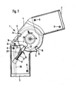
- a hinge 1 of a collapsible multi-purpose ladder which connects the bars 2, 3 of the multi-purpose ladder with each other.
- the joint consists of a first joint part, which is shown in FIGS. 5 to 7.
- the first joint part 4 is composed of two halves 5, 6, each of which is deep-drawn from a metal sheet and which consist of a guide part 7 which has an outer contour which corresponds to the clear inner contour of the spar 2, 3. With this guide part 7, the first joint part is inserted into the spar 2, as shown in Fig. 1.
- the spar 2 and the guide part 7 are fastened with the aid of rivets 8.
- a locking disk 9 is formed in one piece on the guide part 7 and is narrower than the guide part 7.
- the locking disk 9 has a plurality of grooves 10 arranged at a certain angular distance are so that the spars can be fixed in a 90 °, a 135 ° and a 180 ° position to each other.
- Lugs 11 are formed on each side of the grooves 10 of the locking disk 9, each forming a stop surface 12. These lugs are each formed on the same side of the grooves, so that, as will be explained later, they only interact in one direction of rotation with a locking piece 19 which effects the locking.
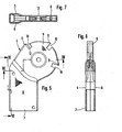
- the locking disk 9 has in its center a bore 13 for receiving the hinge axis 14. In the area of the bore 13, the wall of the locking disk 9 is retracted again, so that this results in better guidance for the second joint part 15, which is shown in detail in FIGS. 2 to 4.
- the second joint part 15 like the first joint part 4, has a guide part 16 which is inserted into the spar 3 and fastened in it by means of rivets 8.
- a tab 17 is formed in the guide part and inwards turned. This tab has a bore 18 which serves to guide the locking piece 19.
- the guide part 19 also has a further recess 20 on both opposite sides, which forms a storage surface 21.
- This storage surface is, as can be seen from Fig. 1, arranged relative to the grooves lO such that it lies above the upper boundary of the groove, which is opposite the nose 11, but below the stop surface 12 of the nose 11, so that in the a direction of movement, the stop surface 12 cooperates with the bolt 22 of the locking piece 19.
- the second joint part 15 also has a bore 23 for the joint axis 14. Furthermore, as can be seen from FIG. 4, this is drawn in in the region of the bore 23, so that this results in a guide surface with the retraction of the locking disk 9 in the region of the bore 13, which in addition to the joint axis 14 also centers the two joint parts he brings.
- the second joint part 15 also has a bore 3.4 through which the axis of the release lever 24 shown in FIGS. 9 to 12 is guided.
- the locking piece 19 is shown.
- the locking piece consists of a bolt 22 which engages in the grooves 10 of the locking disk 9.
- a guide part 25 and a rod 26, which serves as a guide for a compression spring 27, are integrally formed on the bolt 10.
- the width of the latch 22 is slightly less than that of the grooves 10, whereas the height of the latch 22 is equal to or slightly less than the height of the guide part 16 of the second joint part 15.
- the lateral guidance of the bolt 22 is by the side walls 28 of the guide member 16th of the second joint part 15 obtained.
- the adjoining the latch 22 guide member 25 has a lower height, namely this height is at least twice the wall thickness of the side walls 28, so that this guide member 25 comes to rest on the inner walls of the side walls 28 .
- the width of the guide part 25, however, is substantially larger than that of the bolt 10, so that the locking piece 19 is supported in the region of the recess 20.
- the rod 26 is, as can be seen from FIG. 1, inserted through the bore 18 of the tab 17. Between the tab 17 and the guide part 25, a compression spring 27 is arranged, which presses the bolt 22 in the direction of the grooves 10.
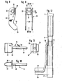
- the release lever 24 is provided with two arms 29 which are connected to one another via a web 30.
- two tabs 31 are arranged laterally, which are bent over the web, so that a small gap 32 remains between these tabs.
- the arms 29 have two bores 33 which have somewhat deep-drawn walls for better guidance of the axis 34 which actuates the release lever.
- This axis has in the region of the release lever 24 lateral projections which engage in the gap 32, so that a rotationally fixed connection of the axis to the release lever is achieved.
- a rod 35 is connected to the axis 34, which is essentially U-shaped and connects the two axes 34 of two joints 1 arranged in parallel. This rod is shown in FIG. 13 and is guided laterally in the area of a rung 39 so that it lies outside the step area.
- the operation of the joint is as follows.
- the release lever 24 moves downward and presses with its contact surface 37 against the bolt 22 of the locking piece 19 and pushes it out of the groove 10.
- the locking piece and thus the bolt 22 is also displaced in the direction of the axis of rotation of the lever, so that the locking piece comes to rest on the storage surface 21.
- the lever can then be released and the joint rotated. If this rotation occurs clockwise in FIG. 1, the spar 2 can be brought into a position parallel to that of the spar 3 without fear of the latch 22 latching into one of the grooves 10. If, on the other hand, the spar 2 is rotated counterclockwise in FIG. 1, the stop surface 12 of the nose 11 comes against the bolt 22 and pushes it away from its storage surface 21, so that it now snaps into the groove 10 due to the force of the spring 27 and so the mobility of the spars 2, 3 blocks against each other.
- a joint according to the invention is characterized by a simple structure with high operational reliability and simple operation.
- the locking mechanism consists of a spring and a locking piece which is guided in the second joint part and can be actuated by a simply designed lever, the release levers of the joints assigned in pairs being actuated simultaneously, so that only one triggering operation is required for this.
- the rod 35 which is connected to the axis 34 for the release lever, is arranged in the area of a rung 39, the folding or folding of the ladder and the actuation of the release lever can take place practically simultaneously, which makes operation considerably easier .
Landscapes
- Ladders (AREA)
- Table Devices Or Equipment (AREA)
Abstract
Description
- Die Erfindung betrifft eine zusammenklappbare Mehrzweckleiter, deren Holme durch paarweise angeordnete und in mehreren Arbeitsstellungen verriegelbare Gelenke verbunden sind, die je zwei um eine gemeinsame Gelenkachse schwenkbare Gelenkteile aufweisen, von denen der erste Gelenkteil eine zur Gelenkachse konzentrische, zweischalige Sperrscheibe aufweist, die im Bereich ihres Umfanges entsprechend den Arbeitsstellungen verteilte Nuten hat, in die ein an dem das erste Gelenkteil übergreifenden zweiten Gelenkteil längsverschieblich geführtes, federbelastetes Sperrstück eingreifen kann, das durch einen an dem zweiten Gelenkteil verschwenkbar gelagerten und mit einem Betätigungshebel verbundenen Lösehebel aus der jeweiligen Ausnehmung der Sperrscheibe aushebbar ist und die Lösungshebel der den beiden Holmen zugeordneten Gelenke durch eine Stange miteinander verbunden sind. Eine derartige Mehrzweckleiter ist aus der DE-OS 27 54 755 bekannt.
- Die Verbindungsstange ist im Inneren eines Holmes geführt, wobei die Betätigung des Lösehebels mit an den Seiten der Holme angeordneten Drehgriffen erfolgt. Diese bekannte Gelenkanordnung ist konstruktiv aufwendig in der Herstellung und störanfällig im Betrieb.
- Der Erfindung liegt die Aufgabe zugrunde, eine zusammenklappbare Mehrzweckleiter der eingangs genannten Art so auszubilden, daß deren Gelenke konstruktiv einfach im Aufbau sind und die Leiter einfach zu bedienen ist.
- Diese Aufgabe wird erfindungsgemäß dadurch gelöst, daß das Sperrstück aus einem rechteckigen Riegel besteht, dessen Höhe in etwa gleich der Breite des zweiten Gelenkteiles ist und in einer Aussparung in den Seitenwänden des zweiten Gelenkteiles geführt ist und aus einem sich hieran anschliessenden Führungsteil, dessen Höhe nur geringfügig kleiner als die lichte Höhe des zweiten Gelenkteiles ist, dessen Breite jedoch größer als die Breite der Aussparung ist und aus einem Führungsteil für die Feder, daß die Aussparung breiter als die Breite des Riegels ist, und eine Ablagefläche für diesen bildet, die den Riegel in seiner ausgesrasteten Stellung hält und daß die die Nuten aufweisende Sperrscheibe gleichsinnig jeweils einen neben den Nuten liegenden Ansatz aufweist, der eine Anschlagfläche für den Riegel des Sperrstückes bildet.
- Ein erfindungsgemäß ausgebildetes Gelenk für eine zusammenklappbare Mehrzweckleiter besteht somit nur aus wenigen Teilen, wobei das Sperrstück so ausgebildet ist, daß dieses sowohl in seitlicher Richtung wie auch in senkrechter Richtung hierzu geführt ist. Die seitliche Führung übernimmt der Riegel, der die gleiche Höhe wie das zweite Gelenkteil aufweist und in einer Ausnehmung desselben geführt ist. Die Führung wird hier durch die seitlichen Wandungen im zweiten Gelenkteil erhalten. Diese Ausnehmung weist eine Verbreiterung auf, so daß hierdurch eine Ablagefläche für die Stirnfläche des Riegels erhalten wird. Beim Ausheben des Riegels aus den Nuten mit Hilfe des Lösehebels wird der Riegel etwas seitlich verschwenkt, so daß dieser auf der Ablagefläche außer Eingriff in den Nuten zur Ablage kommt: Diese bedeutet, daß der Lösehebel beim Verschwenken der Holme um die Gelenkachse nicht weiter betätigt zu werden braucht. Durch die Ausbildung von Ansätzen neben den Nuten, die eine Anschlagfläche für den Riegel bilden, ist sichergestellt, daß bei Erreichen der nächsten Nut der Riegel durch die Anschlagfläche von seiner Ablagefläche weggeschoben wird und selbsttätig in die Nut eingreift. Da die Ablagefläche für den Riegel des Sperrstückes seitlich an einer Seite der Führung angeordnet ist, kann somit dieser Riegel nur bei einer bestimmten Drehrichtung der Holme durch die Anschlagflächen der Nasen von den Ablageflächen abgehoben werden und in die Nuten einrasten. Diese Nasen und Ablageflächen sind so angeordnet, daß beim Zusammenklappen der Holme das Sperrstück gesperrt bleibt, so daß nach einem einmaligen Betätigen des Lösehebels die Leiter im folgenden vollständig zusammengeklappt werden kann. Beim Auseinanderklappen der Leiter hingegen rasten die Sperrstücke der paarweise angeordneten Gelenke jeweils bei der nächsten Nut dann ein, wenn der Lösehebel losgelassen ist. Hierdurch wird eine.einfache Handhabung der Leiter erreicht.
- Gemäß einer weiteren Ausführungsform der Erfindung ist die die beiden Lösungshebel verbindende Stange seitlich neben den Sprossen angeordnet, die den Gelenken benachbart sind. Dies hat den Vorteil für die Bedienung, daß mit ein und demselben Griff die Leiter gehalten und der Lösemechanismus betätigt werden kann, was die Handhabung äußerst vereinfacht.
- Aus sicherheitstechnischen Gründen ist die gestreckte Stellung der Holme gleichfalls durch Einrastung des Sperrstückes in eine entsprechend angeordnete Nut gesichert. Hierdurch erreicht man, daß die Holme auch in dieser Stellung mit Abstand zueinander liegen können, so daß schwerwiegende Verletzungen, wie sie bisher aufgetreten sind und die selbst zum Abquetschen von Fingern geführt haben, nicht mehr eintreten können.
- Ein Ausführungsbeispiel der Erfindung ist im folgenden anhand der Zeichnung näher beschrieben, in dieser zeigen:
- Fig. 1 eine Seitenansicht, teilweise im Schnitt, eines erfindungsgemäß ausgebildeten Gelenks für zusammenklappbare Mehrzweckleitern,
- Fig. 2 das zweite Lagerteil in Seitenansicht,
- Fig. 3 einen Schnitt nach Linie III-III in Fig. 2,
- Fig. 4 einen Schnitt nach Linie IV-IV in Fig. 2,
- Fig. 5 das erste Lagerteil in Seitenansicht,
- Fig. 6 einen Schnitt nach Linie VI-VI in Fig. 5,
- Fig. 7 einen Schnitt nach Linie VII-VII in Fig. 5,
- Fig. 8 eine Draufsicht auf den Lösehebel,
- Fig. 9 einen Schnitt nach Linie IX-IX in Fig. 8,
- Fig.10
- bis 12 das Sperrstück in Seitenansicht, Stirnansicht und Draufsicht und
- Fig. 13 eine Draufsicht auf ein erfindungsgemäß ausgebildetes und zwei Holme miteinander verbindendes Gelenk einer Leiter.
- In Fig. 1 ist ein Gelenk 1 einer zusammenklappbaren Mehrzweckleiter dargestellt, das die Holme 2, 3 der Mehrzweckleiter miteinander verbindet. Das Gelenk besteht aus einem ersten Gelenkteil, das in den Fig. 5 bis 7 dargestellt ist. Das erste Gelenkteil 4 ist aus zwei Hälften 5, 6 zusammengesetzt, die jeweils aus einem Blech tiefgezogen sind und die aus einem Führungsteil 7 bestehen, das eine äußere Kontur aufweist, die der lichten inneren Kontur des Holmes 2, 3 entspricht. Mit diesem Führungsteil 7 wird das erste Gelenkteil in den Holm 2 eingeschoben, wie dies in Fig. 1 gezeigt ist. Die Befestigung von Holm 2 und dem Führungsteil 7 erfolgt mit Hilfe von Nieten 8. Einstückig an das Führungsteil 7 ist eine Sperrscheibe 9 angeformt, die schmäler ist als das Führungsteil 7. Die Sperrscheibe 9 weist mehrere Nuten lO auf, die in einem bestimmten Winkelabstand angeordnet sind, so daß die Holme in einer 90°, einer 135° und einer 180° Stellung zueinander fixiert werden können.
- Jeweils auf einer Seite der Nuten lO der Sperrscheibe 9 sind Nasen 11 angeformt, die je eine Anschlagfläche 12 bilden. Diese Nasen sind jeweils auf der gleichen Seite der Nuten angeformt, so daß, was später erläutert werden wird, diese nur in einer Drehrichtung mit einem die Verriegelung bewirkenden Sperrstück 19 zusammenwirken. Die Sperrscheibe 9 weist in ihrer Mitte eine Bohrung 13 für die Aufnahme der Gelenkachse 14 auf. Im Bereich der Bohrung 13 ist die Wandung der Sperrscheibe 9 noch einmal eingezogen, so daß hierdurch eine bessere Führung für das zweite Gelenkteil 15 erhalten wird, das im einzelnen in den Fig. 2 bis 4 dargestellt ist.
- Das zweite Gelenkteil 15 hat gleichfalls wie das erste Gelenkteil 4 ein Führungsteil 16, das in den Holm 3 eingeschoben und mittels Nieten 8 in diesem befestigt wird. Im Führungsteil ist eine Lasche 17 ausgeformt und nach innen abgebogen. Diese Lasche weist eine Bohrung 18 auf, die zur Führung des Sperrstückes 19 dient. Das Führungsteil 19 weist des weiteren auf beiden gegenüberliegenden Seiten eine weitere Aussparung 20 auf, die eine Ablagefläche 21 bildet. Diese Ablagefläche ist, wie aus Fig. 1 zu ersehen ist, relativ zu den Nuten lO derart angeordnet, daß sie oberhalb der oberen Begrenzung der Nut liegt, die der Nase 11 gegenüberliegt, jedoch unterhalb der Anschlagfläche 12 der Nase 11, so daß in der einen Bewegungsrichtung die Anschlagfläche 12 mit dem Riegel 22 des Sperrstückes 19 zusammenwirkt.
- Das zweite Gelenkteil 15 weist gleichfalls eine Bohrung 23 für die Gelenkachse 14 auf. Des weiteren ist diese, wie aus Fig. 4 zu ersehen ist, im Bereich der Bohrung 23 eingezogen, so daß hierdurch mit der Einziehung der Sperrscheibe 9 im Bereich der Bohrung 13 eine Führungsfläche geschaffen ist, die zusätzlich zur Gelenkachse 14 eine Zentrierung der beiden Gelenkteile erbringt.
- Das zweite Gelenkteil 15 weist darüber hinaus eine Bohrung 3.4 auf, durch die die Achse des in den Fig.-.9 bis 12 dargestellten Lösehebels 24 geführt ist.
- In den Fig. 10 bis 12 ist das Sperrstück 19 dargestellt. Das Sperrstück besteht aus einem Riegel 22, der in die Nuten 10 der Sperrscheibe 9 eingreift. An den iegel 10 ist ein Führungsteil 25 und an dieses eine Stange 26, die als Führung für eine Druckfeder 27 dient,angeformt. Die Breite des Riegels 22 ist etwas geringer als die der Nuten 10, wohingegen die Höhe des Riegels 22 gleich oder etwas geringer als die Höhe des Führungsteiles 16 des zweiten Gelenkteils 15 ist. Die seitliche Führung des Riegels 22 wird durch die Seitenwände 28 des Führungsteiles 16 des zweiten Gelenkteiles 15 erhalten.
- Wie aus Fig.ll hervorgeht, hat das sich an den Riegel 22 anschließende Führungsteil 25 eine geringere Höhe, und zwar ist diese Höhe mindestens um die doppelte Wandstärke der Seitenwände 28 geringer, so daß dieses Führungsteil 25 an den Innenwänden der Seitenwände 28 zur Anlage kommt. Die Breite des Führungsteiles 25 ist hingegen wesentlich größer als die des Riegels 10, so daß auch das Sperrstück 19 im Bereich der Aussparung 20 abgestützt ist. Die Stange 26 ist, wie aus Fig. l ersichtlich, durch die Bohrung 18 der Lasche 17 gesteckt. Zwischen der Lasche 17 und dem Führungsteil 25 ist eine Druckfeder 27 angeordnet, die den Riegel 22 in Richtung der Nuten 10 drückt.
- Am zweiten Gelenkteil 15 ist des weiteren der Lösehebel 24 befestigt, der im einzelnen in den Fig. 8 und 9 dargestellt ist. Der Lösehebel 24 ist mit zwei Armen 29 versehen, die über einen Steg 30 miteinander verbunden sind. Am Steg 30 sind seitlich zwei Laschen 31 angeordnet, die über den Steg gebogen sind, so daß zwischen diesen Laschen ein geringer Spalt 32 verbleibt. Des weiteren weisen die Arme 29 zwei Bohrungen 33 auf, die etwas tiefgezogene Wände zur besseren Führung der die Lösehebel betätigenden Achse 34 haben. Diese Achse hat im Bereich des Lösehebels 24 seitliche Vorsprünge, die in den Spalt 32 eingreifen, so daß hierdurch eine drehfeste Verbindung der Achse mit dem Lösehebel erreicht wird.
- Mit der Achse 34 ist eine Stange 35 verbunden, die im wesentlichen U-förmig ausgebildet ist und die beiden Achsen 34 zweier parallel angeordneter Gelenke 1 miteinander verbindet. Diese Stange ist in Fig.13 dargestellt und im Bereich einer Sprosse 39 seitlich geführt, so daß diese außerhalb des Trittbereiches liegt.
- Die Funktionsweise des Gelenkes ist folgende. Beim Hochheben der Stange bewegt sich der Lösehebel 24 nach unten und drückt mit seiner Anlagefläche 37 gegen den Riegel 22 des Sperrstückes 19 und schiebt diesen aus der Nut lO heraus. Durch die Bewegung des Hebels wird das Sperrstück und damit der Riegel 22 auch in Richtung auf die Drehachse des Hebels hin verschoben, so daß das Sperrstück auf der Ablagefläche 21 zur Anlage kommt. Im Anschluß hieran kann der Hebel losgelassen und das Gelenk verdreht werden. Erfolgt diese Verdrehung im Uhrzeigersinn in Fig.l, so kann der Holm 2, ohne daß ein Einrasten des Riegels 22 in eine der Nuten lO zu befürchten ist, in eine Stellung parallel zu der des Holmes 3 gebracht werden. Wird hingegen der Holm 2 entgegen dem Uhrzeigersinn in Fig.l verdreht, so gelangt die Anschlagfläche 12 der Nase 11 gegen den Riegel 22 und schiebt diesen von seiner Ablagefläche 21 weg, so daß dieser nunmehr aufgrund der Kraft der Feder 27 in die Nut 10 einrastet und so die Bewegbarkeit der Holme 2, 3 gegeneinander sperrt.
- Ein Gelenk gemäß der Erfindung zeichnet sich durch einen einfachen Aufbau bei hoher Betriebssicherheit und einfacher Bedienung aus. Der Sperrmechanismus besteht aus einer Feder und einem Sperrstück, das im zweiten Gelenkteil geführt und durch einen.einfach gestalteten Hebel betätigbar ist, wobei die Lösehebel der einander paarweise zugeordneten Gelenke simultan betätigt werden, so daß hierzu nur ein Auslösevorgang erforderlich ist. Da zudem die Stange 35, die mit der Achse 34 für den Lösehebel verbunden ist, im Bereich einer Sprosse 39 angeordnet ist, kann das Auseinander- bzw. Zusammenklappen der Leiter und die Betätigung der Lösehebel praktisch simultan erfolgen, was eine wesentliche Bedienungserleichterung mit sich bringt.
Claims (5)
Priority Applications (1)
| Application Number | Priority Date | Filing Date | Title |
|---|---|---|---|
| AT83102168T ATE19538T1 (de) | 1982-03-26 | 1983-03-05 | Zusammenklappbare mehrzweckleiter. |
Applications Claiming Priority (2)
| Application Number | Priority Date | Filing Date | Title |
|---|---|---|---|
| DE3211164A DE3211164C2 (de) | 1982-03-26 | 1982-03-26 | Zusammenklappbare Mehrzweckleiter |
| DE3211164 | 1982-03-26 |
Publications (3)
| Publication Number | Publication Date |
|---|---|
| EP0090198A2 true EP0090198A2 (de) | 1983-10-05 |
| EP0090198A3 EP0090198A3 (en) | 1984-07-18 |
| EP0090198B1 EP0090198B1 (de) | 1986-04-30 |
Family
ID=6159378
Family Applications (1)
| Application Number | Title | Priority Date | Filing Date |
|---|---|---|---|
| EP83102168A Expired EP0090198B1 (de) | 1982-03-26 | 1983-03-05 | Zusammenklappbare Mehrzweckleiter |
Country Status (4)
| Country | Link |
|---|---|
| US (1) | US4474264A (de) |
| EP (1) | EP0090198B1 (de) |
| AT (1) | ATE19538T1 (de) |
| DE (2) | DE3211164C2 (de) |
Cited By (2)
| Publication number | Priority date | Publication date | Assignee | Title |
|---|---|---|---|---|
| US4928792A (en) * | 1987-11-04 | 1990-05-29 | Krause Werk Gmbh & Co. Kg | Joint for ladders |
| CN109505506A (zh) * | 2018-12-28 | 2019-03-22 | 彭东丽 | 一种电力专用绝缘梯 |
Families Citing this family (39)
| Publication number | Priority date | Publication date | Assignee | Title |
|---|---|---|---|---|
| US4602889A (en) * | 1984-08-31 | 1986-07-29 | Mu Shan Yeh | Adjustable knuckle joint device for folding ladders |
| DE3446255A1 (de) * | 1984-12-19 | 1986-06-19 | Nikolaus Adalbert 7730 Villingen-Schwenningen Kümmerlin | Leiter |
| US4645371A (en) * | 1986-05-01 | 1987-02-24 | Wang Chien Yuan | Safety joint mechanism, particularly for folding ladders |
| KR910000302Y1 (ko) * | 1987-02-21 | 1991-01-18 | 장문수 | 절첩식 사다리용 경첩 |
| US4773503A (en) * | 1987-09-11 | 1988-09-27 | Robert L. Pease | Ladder hinge |
| US4805737A (en) * | 1987-11-18 | 1989-02-21 | Peng Ching L | Ladder positioning mechanism |
| US4934485A (en) * | 1988-02-08 | 1990-06-19 | Robert Pease | Combination ladder and hand truck |
| US4934696A (en) * | 1988-11-07 | 1990-06-19 | Richard Jackan | Retractable basketball backboard |
| DE3937535C1 (en) * | 1989-11-10 | 1991-03-07 | Rauschenberger Metallwaren Gmbh, 7144 Asperg, De | Joint for folding ladder - has swivel legs with ratchet disc and stop to control pivoting |
| US5022118A (en) * | 1990-06-25 | 1991-06-11 | Wan Dean Industry Co. | Ladder joint with engagement spring member |
| US5279387A (en) * | 1991-09-25 | 1994-01-18 | Emerson Electric Co. | Articulated ladder assembly |
| US5169257A (en) * | 1992-06-26 | 1992-12-08 | Liou Shuen Yi | Angle adjustable joint |
| US5954157A (en) * | 1994-10-18 | 1999-09-21 | Fiberlite Technologies, Inc. | Fiber/resin composite ladder and accompanying accessories |
| DE19901126A1 (de) | 1999-01-14 | 2000-07-20 | Rauschenberger Gmbh U Co | Mehrzweckleiter mit zusammenklappbaren Holmen |
| DE19901125C1 (de) * | 1999-01-14 | 2000-11-16 | Rauschenberger Gmbh U Co | Gelenk, insbesondere zur Verbindung von Leiterholmen |
| US6443261B1 (en) * | 1999-08-13 | 2002-09-03 | Cosco Management, Inc. | Step stool |
| DE29919002U1 (de) | 1999-10-29 | 2000-02-03 | Krause-Werk GmbH & Co KG, 36304 Alsfeld | Leitergelenk |
| DE29919004U1 (de) | 1999-10-29 | 2000-02-03 | Krause-Werk GmbH & Co KG, 36304 Alsfeld | Leitergelenk |
| CA2508885C (en) * | 2002-11-11 | 2011-01-18 | Wing Enterprises, Inc. | Combination ladders, ladder components and methods of manufacturing same |
| US6880835B2 (en) * | 2003-04-11 | 2005-04-19 | Sylmark Holdings Limited | Combination hand truck, step ladder and dolly |
| US6877586B2 (en) * | 2003-04-11 | 2005-04-12 | Sylmark Holdings Limited | Hinge system for combination hand truck, step ladder and dolly device |
| US6991063B2 (en) * | 2003-08-07 | 2006-01-31 | Werner Co. | Stowable ladder configured for installation in an opening |
| US7341392B2 (en) * | 2005-04-22 | 2008-03-11 | Dofair Co., Ltd. | Lock device in an articulated joint for a foldable ladder |
| KR100662454B1 (ko) * | 2005-07-29 | 2007-01-02 | 엘지전자 주식회사 | 평판형 영상표시기를 위한 스탠드 구조 |
| USD553757S1 (en) | 2006-02-11 | 2007-10-23 | Wing Enterprises, Inc. | Ladder hinge pair |
| US20070227819A1 (en) * | 2006-03-28 | 2007-10-04 | Layfield L D | Window cleaning ladder |
| US20080073150A1 (en) * | 2006-09-27 | 2008-03-27 | Lin Fan Nan | Safety Reinforcing Structure for Aluminum Ladder Hinge |
| US8341889B2 (en) * | 2008-09-19 | 2013-01-01 | Hy-Security Gate, Inc. | Coupling apparatus for barrier assemblies and related methods |
| USD630492S1 (en) * | 2009-09-18 | 2011-01-11 | Hy-Security Gate, Inc. | Hinge a cover |
| US20120061182A1 (en) * | 2010-09-09 | 2012-03-15 | Grimes Ronald R | Multi-Positional Articulating Hinge with Internal Stops and Remote Actuation and Methods for Manufacturing the Same |
| US20150259981A1 (en) * | 2014-03-14 | 2015-09-17 | Zdzislaw Bobek | Ladder Guard |
| CN109154172B (zh) * | 2016-06-14 | 2021-03-09 | 伟英企业有限公司 | 梯子、梯子铰链和相关方法 |
| USD860476S1 (en) * | 2017-01-04 | 2019-09-17 | Tricam Industries, Inc. | Hinge for a multi-position ladder |
| USD833643S1 (en) | 2017-07-07 | 2018-11-13 | Tricam Industries, Inc. | Integrated ladder tray hook |
| WO2019018789A1 (en) * | 2017-07-20 | 2019-01-24 | KidKraft, Inc. | ACCORDION FOLDING GAME STRUCTURE WITH EASY ASSEMBLY DEVICE |
| US10723077B2 (en) * | 2018-12-27 | 2020-07-28 | Bulent Besim | System to enable folding in an additive manufacturing machine |
| USD935055S1 (en) | 2019-08-07 | 2021-11-02 | Tricam Industries, Inc. | Hinge for a multi-position ladder |
| US11293481B2 (en) * | 2020-07-21 | 2022-04-05 | Way-Hong Chen | Rotation joint structure with two-stage lock |
| CN114517807A (zh) * | 2022-03-23 | 2022-05-20 | 天津市金锚家居用品有限公司 | 一种改进的铰链开锁机构 |
Family Cites Families (8)
| Publication number | Priority date | Publication date | Assignee | Title |
|---|---|---|---|---|
| US764310A (en) * | 1904-03-16 | 1904-07-05 | Wallace F Shaw | Window-stop. |
| US1532322A (en) * | 1923-06-02 | 1925-04-07 | Lane James Henry | Door catch |
| SE390323B (sv) * | 1969-07-30 | 1976-12-13 | H Hoffmann | Hopfellbar universalstege |
| DE2052584C3 (de) * | 1970-10-27 | 1984-09-27 | Hoffmann, Helmut | Zusammenklappbare Mehrzweckleiter |
| DE2508573A1 (de) * | 1975-02-27 | 1976-09-09 | Bahmueller Masch W | Insbesondere an den leiterholmen einer zusammenklappbaren mehrzweckleiter zu befestigendes, in mehreren stellungen verriegelbares gelenk |
| DE2514940C2 (de) * | 1975-04-05 | 1985-03-07 | Wilhelm Bahmüller Maschinen- und Apparatebau, 7067 Plüderhausen | In mehreren Arbeitsstellungen verriegelbares Gelenk zur Verbindung der Leiterholme einer in mehreren Stellungen verrastbaren Leiter oder dergl. |
| DE2754755C2 (de) * | 1977-12-08 | 1986-10-02 | Wilhelm Bahmüller, Maschinenbau Präzisionswerkzeuge GmbH, 7067 Plüderhausen | Zusammenklappbare Mehrzweckleiter |
| DE2914476A1 (de) * | 1979-04-10 | 1980-10-23 | Bahmueller Masch W | Zusammenklappbare mehrzweckleiter |
-
1982
- 1982-03-26 DE DE3211164A patent/DE3211164C2/de not_active Expired
-
1983
- 1983-03-05 AT AT83102168T patent/ATE19538T1/de not_active IP Right Cessation
- 1983-03-05 DE DE8383102168T patent/DE3363251D1/de not_active Expired
- 1983-03-05 EP EP83102168A patent/EP0090198B1/de not_active Expired
- 1983-03-24 US US06/478,565 patent/US4474264A/en not_active Expired - Lifetime
Cited By (2)
| Publication number | Priority date | Publication date | Assignee | Title |
|---|---|---|---|---|
| US4928792A (en) * | 1987-11-04 | 1990-05-29 | Krause Werk Gmbh & Co. Kg | Joint for ladders |
| CN109505506A (zh) * | 2018-12-28 | 2019-03-22 | 彭东丽 | 一种电力专用绝缘梯 |
Also Published As
| Publication number | Publication date |
|---|---|
| EP0090198A3 (en) | 1984-07-18 |
| US4474264A (en) | 1984-10-02 |
| DE3211164A1 (de) | 1983-10-13 |
| EP0090198B1 (de) | 1986-04-30 |
| ATE19538T1 (de) | 1986-05-15 |
| DE3363251D1 (en) | 1986-06-05 |
| DE3211164C2 (de) | 1985-06-20 |
Similar Documents
| Publication | Publication Date | Title |
|---|---|---|
| EP0090198B1 (de) | Zusammenklappbare Mehrzweckleiter | |
| EP0425786B1 (de) | Leiter | |
| DE3737295C2 (de) | ||
| DE202014010305U1 (de) | Zusammenlegbare Leiter | |
| DE2649430C3 (de) | Faltleiter | |
| DE3227351C2 (de) | Sperrvorrichtung für zwei Schienenpaare eines Fahrzeugsitzes | |
| DE2052584C3 (de) | Zusammenklappbare Mehrzweckleiter | |
| DE20113163U1 (de) | Schubwagen mit Klappvorrichtung | |
| DE3327025A1 (de) | Bockleiter | |
| DE8208700U1 (de) | Zusammenklappbare mehrzweckleiter | |
| DE2914476C2 (de) | ||
| DE3937535C1 (en) | Joint for folding ladder - has swivel legs with ratchet disc and stop to control pivoting | |
| DE1654888C3 (de) | Zusammenklappbare Mehrzweckleiter | |
| DE8504663U1 (de) | Zusammenklappbare mehrzweckleiter | |
| DE3326975A1 (de) | Zusammenlegbare leiter, insbesondere mehrzweckleiter | |
| DE2321346C3 (de) | Gelenkbeschlag für klappbare Leitern | |
| DE2206681B2 (de) | Verriegelbares Gelenk | |
| DE1459039C3 (de) | Beschlag für Kippschwenkflügel von Fenstern | |
| DE8811247U1 (de) | Rastgelenk für eine Mehrzweckleiter | |
| DE1654934B2 (de) | Zusammenklappbare mehrzweckleiter | |
| DE2412570C2 (de) | Als Schiebeleiter oder Staffelei verwendbare Leiter | |
| EP1020614A1 (de) | Mehrzweckleiter mit zusammenklappbaren Holmen | |
| DE3737481A1 (de) | Leitergelenk | |
| DE9406942U1 (de) | Teleskopleiter | |
| DE3104981A1 (de) | Stehleiter |
Legal Events
| Date | Code | Title | Description |
|---|---|---|---|
| PUAI | Public reference made under article 153(3) epc to a published international application that has entered the european phase |
Free format text: ORIGINAL CODE: 0009012 |
|
| AK | Designated contracting states |
Designated state(s): AT BE CH DE FR GB IT LI LU NL SE |
|
| PUAL | Search report despatched |
Free format text: ORIGINAL CODE: 0009013 |
|
| AK | Designated contracting states |
Designated state(s): AT BE CH DE FR GB IT LI LU NL SE |
|
| 17P | Request for examination filed |
Effective date: 19841018 |
|
| ITF | It: translation for a ep patent filed | ||
| GRAA | (expected) grant |
Free format text: ORIGINAL CODE: 0009210 |
|
| AK | Designated contracting states |
Kind code of ref document: B1 Designated state(s): AT BE CH DE FR GB IT LI LU NL SE |
|
| REF | Corresponds to: |
Ref document number: 19538 Country of ref document: AT Date of ref document: 19860515 Kind code of ref document: T |
|
| REF | Corresponds to: |
Ref document number: 3363251 Country of ref document: DE Date of ref document: 19860605 |
|
| ET | Fr: translation filed | ||
| PLBE | No opposition filed within time limit |
Free format text: ORIGINAL CODE: 0009261 |
|
| STAA | Information on the status of an ep patent application or granted ep patent |
Free format text: STATUS: NO OPPOSITION FILED WITHIN TIME LIMIT |
|
| 26N | No opposition filed | ||
| ITTA | It: last paid annual fee | ||
| EPTA | Lu: last paid annual fee | ||
| EAL | Se: european patent in force in sweden |
Ref document number: 83102168.8 |
|
| PGFP | Annual fee paid to national office [announced via postgrant information from national office to epo] |
Ref country code: CH Payment date: 19950228 Year of fee payment: 13 |
|
| PGFP | Annual fee paid to national office [announced via postgrant information from national office to epo] |
Ref country code: LU Payment date: 19950301 Year of fee payment: 13 Ref country code: BE Payment date: 19950301 Year of fee payment: 13 |
|
| PG25 | Lapsed in a contracting state [announced via postgrant information from national office to epo] |
Ref country code: LU Free format text: LAPSE BECAUSE OF NON-PAYMENT OF DUE FEES Effective date: 19960305 |
|
| PG25 | Lapsed in a contracting state [announced via postgrant information from national office to epo] |
Ref country code: LI Effective date: 19960331 Ref country code: CH Effective date: 19960331 Ref country code: BE Effective date: 19960331 |
|
| BERE | Be: lapsed |
Owner name: KRAUSE GUNTHER Effective date: 19960331 |
|
| REG | Reference to a national code |
Ref country code: CH Ref legal event code: PL |
|
| PGFP | Annual fee paid to national office [announced via postgrant information from national office to epo] |
Ref country code: SE Payment date: 20000315 Year of fee payment: 18 |
|
| PGFP | Annual fee paid to national office [announced via postgrant information from national office to epo] |
Ref country code: AT Payment date: 20000329 Year of fee payment: 18 |
|
| PGFP | Annual fee paid to national office [announced via postgrant information from national office to epo] |
Ref country code: NL Payment date: 20000331 Year of fee payment: 18 |
|
| PG25 | Lapsed in a contracting state [announced via postgrant information from national office to epo] |
Ref country code: AT Free format text: LAPSE BECAUSE OF NON-PAYMENT OF DUE FEES Effective date: 20010305 |
|
| PG25 | Lapsed in a contracting state [announced via postgrant information from national office to epo] |
Ref country code: SE Free format text: LAPSE BECAUSE OF NON-PAYMENT OF DUE FEES Effective date: 20010306 |
|
| PG25 | Lapsed in a contracting state [announced via postgrant information from national office to epo] |
Ref country code: NL Free format text: LAPSE BECAUSE OF NON-PAYMENT OF DUE FEES Effective date: 20011001 |
|
| EUG | Se: european patent has lapsed |
Ref document number: 83102168.8 |
|
| NLV4 | Nl: lapsed or anulled due to non-payment of the annual fee |
Effective date: 20011001 |
|
| REG | Reference to a national code |
Ref country code: GB Ref legal event code: IF02 |
|
| PGFP | Annual fee paid to national office [announced via postgrant information from national office to epo] |
Ref country code: GB Payment date: 20020306 Year of fee payment: 20 |
|
| PGFP | Annual fee paid to national office [announced via postgrant information from national office to epo] |
Ref country code: FR Payment date: 20020328 Year of fee payment: 20 |
|
| PGFP | Annual fee paid to national office [announced via postgrant information from national office to epo] |
Ref country code: DE Payment date: 20020522 Year of fee payment: 20 |
|
| PG25 | Lapsed in a contracting state [announced via postgrant information from national office to epo] |
Ref country code: GB Free format text: LAPSE BECAUSE OF EXPIRATION OF PROTECTION Effective date: 20030304 |
|
| REG | Reference to a national code |
Ref country code: GB Ref legal event code: PE20 Effective date: 20030304 |