EP0086536B2 - Assemblage des lames coupantes à mouvement de va-et-vient pour rasoir à sec - Google Patents
Assemblage des lames coupantes à mouvement de va-et-vient pour rasoir à sec Download PDFInfo
- Publication number
- EP0086536B2 EP0086536B2 EP83200202A EP83200202A EP0086536B2 EP 0086536 B2 EP0086536 B2 EP 0086536B2 EP 83200202 A EP83200202 A EP 83200202A EP 83200202 A EP83200202 A EP 83200202A EP 0086536 B2 EP0086536 B2 EP 0086536B2
- Authority
- EP
- European Patent Office
- Prior art keywords
- cutter
- lamella
- knife
- lamellae
- pair
- Prior art date
- Legal status (The legal status is an assumption and is not a legal conclusion. Google has not performed a legal analysis and makes no representation as to the accuracy of the status listed.)
- Expired
Links
- 241000446313 Lamella Species 0.000 claims description 49
- 238000005520 cutting process Methods 0.000 claims description 26
- 239000011888 foil Substances 0.000 claims description 6
- 230000001154 acute effect Effects 0.000 claims description 4
- 230000036316 preload Effects 0.000 claims description 2
- 230000003993 interaction Effects 0.000 description 5
- 238000010276 construction Methods 0.000 description 3
- 230000000694 effects Effects 0.000 description 3
- 239000000463 material Substances 0.000 description 3
- 238000004140 cleaning Methods 0.000 description 2
- 230000007423 decrease Effects 0.000 description 2
- 239000002245 particle Substances 0.000 description 2
- 238000012216 screening Methods 0.000 description 2
- 230000009471 action Effects 0.000 description 1
- 238000005452 bending Methods 0.000 description 1
- 230000002349 favourable effect Effects 0.000 description 1
- 230000006872 improvement Effects 0.000 description 1
- 238000004519 manufacturing process Methods 0.000 description 1
- 238000000034 method Methods 0.000 description 1
- 238000012986 modification Methods 0.000 description 1
- 230000004048 modification Effects 0.000 description 1
- 230000035515 penetration Effects 0.000 description 1
- 230000008569 process Effects 0.000 description 1
Images

Classifications
-
- B—PERFORMING OPERATIONS; TRANSPORTING
- B26—HAND CUTTING TOOLS; CUTTING; SEVERING
- B26B—HAND-HELD CUTTING TOOLS NOT OTHERWISE PROVIDED FOR
- B26B19/00—Clippers or shavers operating with a plurality of cutting edges, e.g. hair clippers, dry shavers
- B26B19/02—Clippers or shavers operating with a plurality of cutting edges, e.g. hair clippers, dry shavers of the reciprocating-cutter type
- B26B19/04—Cutting heads therefor; Cutters therefor; Securing equipment thereof
- B26B19/044—Manufacture and assembly of cutter blocks
-
- B—PERFORMING OPERATIONS; TRANSPORTING
- B26—HAND CUTTING TOOLS; CUTTING; SEVERING
- B26B—HAND-HELD CUTTING TOOLS NOT OTHERWISE PROVIDED FOR
- B26B19/00—Clippers or shavers operating with a plurality of cutting edges, e.g. hair clippers, dry shavers
- B26B19/38—Details of, or accessories for, hair clippers, or dry shavers, e.g. housings, casings, grips, guards
- B26B19/42—Details of, or accessories for, hair clippers, or dry shavers, e.g. housings, casings, grips, guards providing for straightening the hair to be cut, e.g. by means of bristles; providing for tensioning the skin, e.g. by means of rollers, ledges
Definitions
- the invention relates to a back and forth drivable bottom knife for dry shavers, which is intended to interact with a Siebscher film and has a number of spaced apart, arranged on at least one support, curved knife blades, at least the distances between one knife blade and the two neighboring ones Knife lamellae are not the same size and, when the knife lamellae are grouped in pairs, at least in the apex area of the knife lamellae the distance between the two knife lamellae of this group and the knife lamella of an adjacent group lying next to it.
- the invention has set itself the task of further improving a lower knife of the type mentioned in terms of the shaving performance that can be achieved with it.
- this object is achieved in that, in a manner known per se, the knife blades are designed to be resilient in the at least one of the two directions of the reciprocating drive movement for the lower knife, of the two knife blades of a group, in each of the seen in both directions of movement, in each case the front knife blade acts as a flexible forward knife in its function and the rear knife blade acts as a stiff cutting knife in its function, and that the two knife blades of a group are provided with an angulation directed towards one another and formed by at least one slat section, at least in the apex region are.
- a leading knife is understood to mean a hair pulling element which pulls the hair out of its skin pocket before it is cut off by the subsequent cutting knife, as is the case for example from AT-PS 333.151, AT-PS 360.375 or also from US-PS 3,088,205 and the DE-OS 2.850.827 emerges.
- the function of the slat angle in each slat group leading to a reduced slat distance in the area of the slat apex in cooperation with the elastic design of the slats, depending on the direction of movement of the lower knife, is one of the two knife slats of a group as a flexible leading knife and the other Knife blade favors as a rigid cutting knife, as will be explained in more detail later.
- the space between adjacent groups of knife blades in the apex area is enlarged, which facilitates the entry of the hair into the holes in the screen shaving foil, which likewise contributes to improving the shaving performance.
- each knife lamella is formed by two lamella sections angled in opposite directions. This makes it possible to arrange the two knife blades, each forming a group, on the carrier side at a somewhat greater distance, which can be advantageous with regard to their mounting on the carrier.
- the angled lamella sections of the two blade lamellae which form a group are arranged so as to lie against one another with pretension. This particularly favors a perfect interaction of the two knife blades forming a group in the course of a cutting process.
- the self-cleaning with regard to adhering hair particles results from the knife lamella sliding smoothly against one another in the course of the cutting process.
- the angled lamella sections in the apex region of the two knife lamellae forming a group each extend in a plane running perpendicular to the direction of movement of the lower knife. This makes it possible to utilize a larger circumferential area of the knife blades for the function as a leading knife.
- the desired elastic resilience of the knife blades can be achieved by appropriate choice of the hardness of their material and / or their thickness. In this context, it has proven to be very advantageous if the knife blades have at least one recess on the carrier side in order to increase their elastic resilience. In this way, the knife slats can be largely optimally dimensioned with regard to their cutting properties, because their desired elastic compliance is achieved or increased by the provision of the recess.
- the carrier-side distance between a knife blade of a group and the knife blade of the adjacent group lying next to it is selected in the order of magnitude of twice the carrier-side distance between the knife blades of a group.
- Figure 1 shows a section along the line I-I in Figure 2, a lower knife with resilient knife blades, the two knife blades of a group each having an angled lamella section facing each other in the apex area.
- Figure 2 shows the lower knife of Figure 1 in a longitudinal section along the line 11-11 in Figure 1.
- Figures 3a to 3c the sequence of movements when cutting a hair with a lower knife according to Figures 1 and 2 is shown schematically.
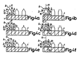
- Figures 4a to 4f schematically show different embodiments of lower knives with knife blades, which are provided with different angles.
- the knife blades 3 are arranged in pairs in groups 4. Knife blades are used which are designed to be elastically flexible in the two directions of the reciprocating drive movement for the lower knife, which can be done by choosing their thickness and / or the hardness of the material used. In order to increase such flexibility or to achieve greater independence from the dimensioning of the knife blades, the individual knife blades here are also provided with a recess 14 on the carrier side. The resilience of the knife blades ensures that of the two knife blades 3 of a group 4, viewed in each of the two directions of movement, the front knife blade acts as a so-called leading knife and the rear knife blade as a so-called cutting knife, which will be discussed in more detail below.
- the blade lamellae 3 are designed such that in the area of the two supports 1 and 2 they have lamella sections 15 which are parallel to one another and run transversely to the direction of movement of the lower knife and are used for mounting the blade lamellae on the two supports, to which lamella sections 16 are connected towards the apex region 5 which are angled relative to sections 15.
- the knife blades 3 are mounted on the supports 1 and 2 in such a way that the bends of the two knife blades 3 of a group 4 formed by the sections 16 are directed toward one another in the apex region 5.
- these bends are carried out in such a way that the sections 16 form an acute angle of the order of 10 ° with a plane 17 running perpendicular to the direction of movement of the lower knife, as can be seen in FIG. 2.
- the arrangement of the knife blades 3 on the supports 1 and 2 is in this case further made such that the angled blade segments 16 of the two blade blades 3 forming a group 4 lying in the apex region 5 bear against one another with prestress.
- the carrier-side distance c between the two knife blades 3 of a group 4 is selected to be smaller than the carrier-side distance d between the facing knife blades 3 of two adjacent groups 4. It has proven to be very advantageous if the distance c is of the order of five times the thickness s of a knife blade and the distance d in the order of twice the distance c is selected, the thickness s of a knife blade being 0.08 mm.
- the knife lamellas punched out from a flat material in an arcuate manner are subsequently formed with the lamella section 16.
- the lamella section 16 Provide bend and then in pairs, with bends facing each other, pushed onto the tubes forming the beams 1 and 2 and fixed on them with the corresponding distances c and d.
- the circumferential surfaces of all knife blades are then subjected to a common grinding process, which ensures that a sieve shear foil fits snugly over the entire circumferential area of the knife blades.
- FIGS. 3a to 3c show the state before a cutting process, in which a hair 7 has passed through a hole 8 in the screen shear film 9 and already between the web 11 of the screen shear film 9 delimiting this hole 8 in the direction of movement 10 and the first knife blade 3 also seen in the direction of movement 10 a group 4 of two knife blades 3 is clamped.
- the free end of the section 16 of this first knife blade 3 hooks onto the hair 7 and pulls on it, the section 16 of this knife blade being bent towards the second knife blade 3 of this group 4 due to its elastic flexibility.
- Such a cutting process cuts a hair shorter than is normally possible.
- Three factors are now relevant for this. The most important factor is that the first knife blade, which is moving in the direction of movement of the lower knife, pulls on the hair 7 before the actual cutting process, so that it is pulled out of its hair pocket a little and pulled further into the hole 8 of the screening shear film, resulting in a longer one Hair piece is available for the cutting process. Furthermore, an additional piece of hair 7 is pushed into the hole 8 of the sieve shear film by the local deformation of the sieve shear film 9 in the region of the hole 8, in which the film is pressed towards the skin, and is thus also subjected to the cutting process.
- the blade blade 3 lying in front in the direction of movement of the lower blade in a group 4 of blade blades 3 is thus a functionally flexible leading blade and thus a hair pulling element and the blade blade 3 following in this direction of motion of the lower blade, which is only effective of the leading knife gains in stiffness, effective as a stiff cutting knife in its function.
- the construction of the lower knife is very simple, since only two knife blades fulfill these functions and it is not necessary to assign a separate leading knife to each of the two directions of movement, as is known per se.
- the two knife lamellae 3 forming a group 4 of course only lie against one another with their angled sections 16 exactly at the apex. Starting from this apex, the distance between these two knife blades increases on both sides until the end of the bend on the carrier side is reached, after which the two knife blades with their sections 15 then run coparally to one another.
- the result of this is that the mode of operation of the knife blades 3 as a preliminary knife and hair pulling element is essentially limited to the apex region 5 of the sections 16 of the knife blades, but this does not constitute a significant disadvantage.
- the area mainly involved in a shave is, because of the usual handling of a dry shaver, the apex area, but where the desired functionality is guaranteed.
- a further advantageous effect occurs here, which is due to the fact that the distance between the two knife blades 3 of a group 4 is chosen to be smaller than the distance between the knife blades 3 facing one another of two adjacent groups 4.
- the distance between the two knife blades 3 of a group 4 is increased in the circumferential direction, namely their elastic flexibility also decreases, which has the consequence that both knife blades act laterally from the apex area as rigid cutting knives.
- both knife blades act laterally from the apex area as rigid cutting knives.
- the greater distance between the mutually facing knife blades of two adjacent groups of knife blades again ensures that the penetration of the hair into the holes in the screen shaving foil is not hindered. Seen overall, a substantial improvement in shaving performance is obtained with such a lower knife.
- 4a to 4f are further exemplary embodiments of lower knives with ela resilient knife blades discussed.
- the knife lamellae with their carrier-side sections 15 are arranged at equal distances g from one another on the carrier 1 indicated by a single block.
- All of these exemplary embodiments can also be carried out with correspondingly different carrier-side distances between the knife blades.
- Any support structures can also be used.
- the exemplary embodiments dealt with here are therefore only intended to show further embodiments which are possible in principle with regard to the design and arrangement of the knife blades.
- the two knife lamellae 3 of a group 4 in the apex region 5 are provided with an angled connection which adjoins the lamella section 15 on the support side and is formed by a single lamella section 16, analogously to the exemplary embodiment according to FIGS. 1 and 2
- the angled lamella sections 16 have a greater inclination with respect to a plane 17 running perpendicular to the direction of movement of the lower knife, with the result that the carrier-side distances of the knife lamellas forming a group can be selected to be larger, thereby facilitating the assembly of such a lower knife .
- the exemplary embodiment according to FIG. 4b shows an arrangement similar to FIG. 4a, however the angled lamella sections 16 of the two knife lamellae 3 forming a group 4 lying in the apex region have a distance h from one another at their free ends, as a result of which the area for the resilient adjustability of a knife blade effective as a leading knife is larger and the hair pulling effect is also increased.
- the exemplary embodiment according to FIG. 4b shows an arrangement similar to FIG. 4a, however the angled lamella sections 16 of the two knife lamellae 3 forming a group 4 lying in the apex region have a distance h from one another at their free ends, as a result of which the area for the resilient adjustability of a knife blade effective as a leading knife is larger and the hair pulling effect is also increased.
- each knife lamella is formed by two sections 19 and 20 angled in opposite directions, the angled lamella sections 19 of the two knife lamellae 3 forming a group 4 each having a plane 17 which is perpendicular to the direction of movement of the lower knife Form angles of the order of 10 ° and rest against each other with pre-tension.
- the sections 20 are then inclined correspondingly more with respect to the plane 17.
- FIG. 4d shows an arrangement of the knife blades 3 analogous to FIG. 4c, but the angled blade sections 19 of the two knife blades 3 forming a group 4, which are located in the apex region, run with their free ends at a distance from one another, just as in the exemplary embodiment according to FIG. 4b.
- the angling of the knife lamellae is again formed by two lamella sections 19 and 20 angled in opposite directions, but here the lamella sections 19 of the two knife lamellae 3 forming a group 4 are in each case in the apex region a plane 17 running perpendicular to the direction of movement of the lower knife.
- the lamella sections 19 rest against one another in the apex region with prestress. Accordingly, the two mutually parallel lamella sections 19 of the two knife lamellae 3 forming a group 4 adjoin one another flatly.
- a knife lamella 3 When a knife lamella 3 functions as a leading knife, its section 19 then moves along the section 19 of the other knife lamella 3 of the relevant group 4 of knife lamellae 3, which acts as a cutting knife.
- the functional area for a leading knife then extends over the Whole circumferential area of the sections 19, but only a smaller adjustment path is obtained for the knife blade which acts as a leading knife.
- An enlargement of this adjustment path for the knife blade acting as the leading knife can be obtained again if the angled sections 19 of the two knife plates 3 forming a group 4 run at a distance h from one another, as is shown by the exemplary embodiment according to FIG. 4f.
Landscapes
- Engineering & Computer Science (AREA)
- Life Sciences & Earth Sciences (AREA)
- Forests & Forestry (AREA)
- Mechanical Engineering (AREA)
- Manufacturing & Machinery (AREA)
- Dry Shavers And Clippers (AREA)
- Cosmetics (AREA)
Claims (10)
Applications Claiming Priority (2)
| Application Number | Priority Date | Filing Date | Title |
|---|---|---|---|
| AT0054482A AT386149B (de) | 1982-02-12 | 1982-02-12 | Hin- und hergehend antreibbares untermesser fuer trockenrasierapparate |
| AT544/82 | 1982-02-12 |
Publications (3)
| Publication Number | Publication Date |
|---|---|
| EP0086536A1 EP0086536A1 (fr) | 1983-08-24 |
| EP0086536B1 EP0086536B1 (fr) | 1985-06-26 |
| EP0086536B2 true EP0086536B2 (fr) | 1989-08-30 |
Family
ID=3493412
Family Applications (1)
| Application Number | Title | Priority Date | Filing Date |
|---|---|---|---|
| EP83200202A Expired EP0086536B2 (fr) | 1982-02-12 | 1983-02-09 | Assemblage des lames coupantes à mouvement de va-et-vient pour rasoir à sec |
Country Status (7)
| Country | Link |
|---|---|
| US (1) | US4536956A (fr) |
| EP (1) | EP0086536B2 (fr) |
| JP (1) | JPS58146382A (fr) |
| AT (1) | AT386149B (fr) |
| CA (1) | CA1206330A (fr) |
| DE (1) | DE3360315D1 (fr) |
| ES (1) | ES279772Y (fr) |
Families Citing this family (9)
| Publication number | Priority date | Publication date | Assignee | Title |
|---|---|---|---|---|
| NL8600878A (nl) * | 1986-04-08 | 1987-11-02 | Philips Nv | Scheerapparaat. |
| JPH06105969A (ja) * | 1992-09-30 | 1994-04-19 | Tokyo Electric Co Ltd | 電気かみそり |
| US6233829B1 (en) * | 1996-08-02 | 2001-05-22 | The Gillette Company | Razor blade |
| DE10352831B4 (de) * | 2003-11-12 | 2007-06-14 | Braun Gmbh | Untermesser für einen oszillierend angetriebenen Scherkopf eines Rasierapparats |
| US7191522B2 (en) * | 2004-06-04 | 2007-03-20 | Rovcal, Inc. | Cutting blade and cutting blade assembly for electric shaver |
| US20060143924A1 (en) * | 2004-12-30 | 2006-07-06 | Rovcal, Inc. | Electric shaver |
| DE102009031627A1 (de) | 2009-07-03 | 2011-01-05 | Braun Gmbh | Untermesser-Baugruppe für Trockenrasierer |
| DE102009031626A1 (de) | 2009-07-03 | 2011-01-05 | Braun Gmbh | Schereinheit für einen Trockenrasierer mit Hautprotektoren |
| DE102009031628A1 (de) | 2009-07-03 | 2011-01-05 | Braun Gmbh | Untermesser für Trockenrasierer |
Family Cites Families (6)
| Publication number | Priority date | Publication date | Assignee | Title |
|---|---|---|---|---|
| US2286443A (en) * | 1939-05-16 | 1942-06-16 | John T Scully | Shaving machine |
| AT181527B (de) * | 1953-12-17 | 1955-03-25 | Gerhard Dipl Ing Heyek | Untermesser für den Scherkopf von Trockenrasierapparaten |
| US3028668A (en) * | 1960-08-16 | 1962-04-10 | Dechaux Charles | Dry shaver with rocking cutter |
| US3088205A (en) * | 1961-09-15 | 1963-05-07 | Ellis Robert | Dry shaver with hair pulling means to aid in cutting the hair |
| NL7713047A (nl) * | 1977-11-28 | 1979-05-30 | Philips Nv | Scheerapparaat. |
| NL7909059A (nl) * | 1979-12-17 | 1981-07-16 | Philips Nv | Scheerapparaat. |
-
1982
- 1982-02-12 AT AT0054482A patent/AT386149B/de not_active IP Right Cessation
- 1982-09-02 US US06/414,159 patent/US4536956A/en not_active Expired - Fee Related
-
1983
- 1983-02-09 EP EP83200202A patent/EP0086536B2/fr not_active Expired
- 1983-02-09 DE DE8383200202T patent/DE3360315D1/de not_active Expired
- 1983-02-09 JP JP58019009A patent/JPS58146382A/ja active Pending
- 1983-02-10 ES ES1983279772U patent/ES279772Y/es not_active Expired
- 1983-02-10 CA CA000421346A patent/CA1206330A/fr not_active Expired
Also Published As
| Publication number | Publication date |
|---|---|
| CA1206330A (fr) | 1986-06-24 |
| DE3360315D1 (en) | 1985-08-01 |
| ES279772U (es) | 1985-06-01 |
| US4536956A (en) | 1985-08-27 |
| AT386149B (de) | 1988-07-11 |
| JPS58146382A (ja) | 1983-08-31 |
| ATA54482A (de) | 1985-06-15 |
| ES279772Y (es) | 1986-01-01 |
| EP0086536A1 (fr) | 1983-08-24 |
| EP0086536B1 (fr) | 1985-06-26 |
Similar Documents
| Publication | Publication Date | Title |
|---|---|---|
| DE102008046072A1 (de) | Scherkopf für einen Rasierapparat | |
| DE2344994A1 (de) | Trockenrasiergeraet | |
| EP0077093B1 (fr) | Appareil de rasage à sec et feuille perforée pour un tel rasoir | |
| EP3900896A1 (fr) | Ensemble de coupe pourvu de bord de coupe ondulaire | |
| DE202009009955U1 (de) | Haartrimmer | |
| EP0086536B2 (fr) | Assemblage des lames coupantes à mouvement de va-et-vient pour rasoir à sec | |
| DE102009035232B4 (de) | Schneidsatz für Haarschneidemaschinen | |
| DE3521897C2 (fr) | ||
| DE4405576C2 (de) | Scherkopf für Naßrasierapparate | |
| EP0477132B1 (fr) | Une unité de lame avec un element de soutien/guidage | |
| DE2836959C2 (de) | Langhaarscherteil, für Trockenrasierapparate | |
| DE3629527A1 (de) | Gitter, vorzugsweise metallgitter | |
| DE2751472A1 (de) | Trockenrasiergeraet | |
| DE69308754T2 (de) | Rasiergerät mit einem folienartigen Ober- und Untermesser | |
| DE2817481A1 (de) | Scherkopf fuer trockenrasierapparate | |
| WO2002070212A1 (fr) | Systeme de rasage pour un rasoir electrique | |
| DE2412099A1 (de) | Aeusseres messerblatt fuer den scherkopf eines elektrischen trockenrasiergeraetes | |
| DE2850827A1 (de) | Rasiergeraet | |
| DE2425298A1 (de) | Trockenrasiergeraet | |
| DE1553717A1 (de) | Scherkopf fuer Trockenrasierapparate | |
| DE2801266A1 (de) | Elektrisches trockenrasiergeraet | |
| DE959803C (de) | Trockenrasier- und Haarschneideapparat | |
| DE2850811A1 (de) | Rasiergeraet | |
| DE2945740C2 (fr) | ||
| DE3906351C2 (de) | Messerklinge für Mähmesser von Erntemaschinen |
Legal Events
| Date | Code | Title | Description |
|---|---|---|---|
| PUAI | Public reference made under article 153(3) epc to a published international application that has entered the european phase |
Free format text: ORIGINAL CODE: 0009012 |
|
| AK | Designated contracting states |
Designated state(s): CH DE FR GB IT LI SE |
|
| 17P | Request for examination filed |
Effective date: 19830921 |
|
| ITF | It: translation for a ep patent filed | ||
| GRAA | (expected) grant |
Free format text: ORIGINAL CODE: 0009210 |
|
| AK | Designated contracting states |
Designated state(s): CH DE FR GB IT LI SE |
|
| REF | Corresponds to: |
Ref document number: 3360315 Country of ref document: DE Date of ref document: 19850801 |
|
| ET | Fr: translation filed | ||
| PLBI | Opposition filed |
Free format text: ORIGINAL CODE: 0009260 |
|
| 26 | Opposition filed |
Opponent name: BRAUN AG, FRANKFURT Effective date: 19860308 |
|
| PGFP | Annual fee paid to national office [announced via postgrant information from national office to epo] |
Ref country code: FR Payment date: 19890221 Year of fee payment: 7 |
|
| PGFP | Annual fee paid to national office [announced via postgrant information from national office to epo] |
Ref country code: SE Payment date: 19890224 Year of fee payment: 7 |
|
| ITTA | It: last paid annual fee | ||
| PG25 | Lapsed in a contracting state [announced via postgrant information from national office to epo] |
Ref country code: LI Effective date: 19890228 Ref country code: CH Effective date: 19890228 |
|
| PGFP | Annual fee paid to national office [announced via postgrant information from national office to epo] |
Ref country code: GB Payment date: 19890228 Year of fee payment: 7 |
|
| PUAH | Patent maintained in amended form |
Free format text: ORIGINAL CODE: 0009272 |
|
| STAA | Information on the status of an ep patent application or granted ep patent |
Free format text: STATUS: PATENT MAINTAINED AS AMENDED |
|
| 27A | Patent maintained in amended form |
Effective date: 19890830 |
|
| AK | Designated contracting states |
Kind code of ref document: B2 Designated state(s): CH DE FR GB IT LI SE |
|
| REG | Reference to a national code |
Ref country code: CH Ref legal event code: PL |
|
| PG25 | Lapsed in a contracting state [announced via postgrant information from national office to epo] |
Ref country code: DE Effective date: 19891101 |
|
| EN3 | Fr: translation not filed ** decision concerning opposition | ||
| PG25 | Lapsed in a contracting state [announced via postgrant information from national office to epo] |
Ref country code: GB Effective date: 19900209 |
|
| PG25 | Lapsed in a contracting state [announced via postgrant information from national office to epo] |
Ref country code: SE Effective date: 19900210 |
|
| GBPC | Gb: european patent ceased through non-payment of renewal fee | ||
| PG25 | Lapsed in a contracting state [announced via postgrant information from national office to epo] |
Ref country code: FR Effective date: 19901031 |
|
| REG | Reference to a national code |
Ref country code: FR Ref legal event code: ST |
|
| EUG | Se: european patent has lapsed |
Ref document number: 83200202.6 |