EP0085854B1 - Pipettiervorrichtung - Google Patents
Pipettiervorrichtung Download PDFInfo
- Publication number
- EP0085854B1 EP0085854B1 EP83100409A EP83100409A EP0085854B1 EP 0085854 B1 EP0085854 B1 EP 0085854B1 EP 83100409 A EP83100409 A EP 83100409A EP 83100409 A EP83100409 A EP 83100409A EP 0085854 B1 EP0085854 B1 EP 0085854B1
- Authority
- EP
- European Patent Office
- Prior art keywords
- locking
- syringe
- stop
- actuating
- piston
- Prior art date
- Legal status (The legal status is an assumption and is not a legal conclusion. Google has not performed a legal analysis and makes no representation as to the accuracy of the status listed.)
- Expired
Links
- 230000033001 locomotion Effects 0.000 claims description 14
- 230000006835 compression Effects 0.000 claims description 4
- 238000007906 compression Methods 0.000 claims description 4
- 230000005540 biological transmission Effects 0.000 claims description 3
- 210000003813 thumb Anatomy 0.000 description 3
- 238000000034 method Methods 0.000 description 2
- 230000000694 effects Effects 0.000 description 1
- 230000002349 favourable effect Effects 0.000 description 1
- 238000012423 maintenance Methods 0.000 description 1
Images
Classifications
-
- B—PERFORMING OPERATIONS; TRANSPORTING
- B01—PHYSICAL OR CHEMICAL PROCESSES OR APPARATUS IN GENERAL
- B01L—CHEMICAL OR PHYSICAL LABORATORY APPARATUS FOR GENERAL USE
- B01L3/00—Containers or dishes for laboratory use, e.g. laboratory glassware; Droppers
- B01L3/02—Burettes; Pipettes
- B01L3/021—Pipettes, i.e. with only one conduit for withdrawing and redistributing liquids
- B01L3/0217—Pipettes, i.e. with only one conduit for withdrawing and redistributing liquids of the plunger pump type
- B01L3/0234—Repeating pipettes, i.e. for dispensing multiple doses from a single charge
Definitions
- the invention relates to a pipetting device as a holding mechanism for a detachable syringe, consisting of a syringe housing and piston for stepless adjustment of the desired working volume with two mutually movable, toothed racks and connected by a gear slide, one of which is connected to a lifting rod for the piston .
- the pipetting device relates to a mechanical actuating part in combination with a syringe, in particular a syringe housing, in which a piston can be moved, the stroke of which can be adjusted in fractions of the volume of the syringe housing.
- the cited literature reference also shows an embodiment with only one actuating lever.
- this embodiment is subject to the disadvantage that a strong spring must be used, which must be dimensioned to return the entire mechanism, including the syringe plunger. This also leads to the disadvantage of fatigue. If the spring in the other known embodiment with the two slides is also avoided because the forces may be somewhat lower in spite of the friction values involved and the counterweight, this also results in the disadvantages described above.
- the invention has for its object to improve a pipetting device of the type mentioned with two slides connected by a gear in that the ease of use is increased and the operating forces are reduced at all.
- the object is achieved in that only one actuating lever is arranged for the piston movements and an actuating device is provided between it and the slides, which has a stop element that can be switched alternately into the path of the other slider depending on a return of the actuating lever to the starting position, wherein a feedback device has at least one weak tension spring, which automatically brings about the feedback.
- the stop element is particularly advantageously engaged with a movable cam, through which the stop element can be displaced, and the cam is under the action of a pretension and a tensioning element which can be acted upon by at least one slide.
- This cam practically leads to a negligible load on the actuating lever only in the first part of the way.
- an expedient embodiment is that the stop element is designed as a cross slide with an actuating wedge which comes into contact with the cam, the cross slide being alternately laterally displaceable by running onto a counter flank of the cam.
- the invention provides a simple switching device for actuating both slides by means of only one actuating lever.
- This preferably includes a stop lock for the cross slide in the respective position with automatic detachment in the starting position of the actuating lever.
- a locking slide with abutments is provided for its return springs.
- This locking slide is designed with two parts that can be moved relative to one another, locking slide part and latching support, between which compression springs are arranged.
- the stop element is transversely displaceably mounted on the locking carrier, with stops arranged in the housing for the end position of the locking slide, which come into engagement with abutments on the locking slide part, and the locking carrier can be moved by the actuating button.
- the actuating device is movable against the return spring arrangement, which is provided for the return movement of only the actuating device with actuating lever, and in the starting position the stop element with end stops in the starting position of the actuating device is in each case with an end stop in front of a surface serving as a slide stop in the retracted position of the slide.
- This also results in a weak return spring arrangement, because only the mechanics can be moved, while in the known embodiment, in the case of a return spring, the piston return stroke must also be carried out with the acting forces. In this respect, the ease of use of the invention is improved.
- the invention advantageously has a continuously variable adjustment of the volume to be sucked in by means of a tight-tolerance screw spindle known per se for adjusting a volume-determining abutment and by a gear connected to the spindle, on the other side of which a digital display is arranged.
- the value set in each case can be read on the digital display.
- a window with a decimal point in the housing is used for this purpose.
- the combination of infinitely variable adjustment by means of a tight-tolerance screw spindle with a drive mechanism, which has two mutually movable sliders, is a feature, especially in connection with the only one actuating lever, which only has to be acted upon by relatively weak return springs in relation to the piston movement.
- the preferred embodiment has a stroke limiting frame which is fixedly arranged in the lower housing part and in which the abutment or stop is guided and through which on the other hand a lifting rod is guided which is connected to a piston rod of the syringe, whereby two abutments are formed.
- the stroke limitation is easily adjustable, a further advantageous feature being that the piston rod head is designed with a groove in which a projection engages in an insert receptacle for the piston rod head, which insert receptacle is arranged in the guide block.
- a locking arrangement advantageously has a guide block on which the lifting rod is fixedly arranged with a stop, and has a swivel bolt which is assigned an opening section for pivoting out at the syringe-side end of the housing, and by means of a double-sided pressure spring provided at the outer end of the recess Equipped u-shaped holder for the use of a syringe housing, which can be removed independently of the syringe plunger. The syringe plunger and the entire syringe housing can be replaced in the lower stop position.
- the axially fixed arrangement of the piston rod head initially ensures proper transmission of the volume setting, and in connection with the stroke limiting frame, such a volume setting is easily transferred.
- the ability to replace the syringe barrel, regardless of the syringe plunger, is a particular advantage in this context.
- the infinitely variable setting is created in conjunction with an adjustment knob on which the spindle is guided so that it can rotate but can move axially, by means of a movement brake for the knob.
- This is expediently designed as a brake shoe running on a rotating disk.
- a diameter which is connected to the rotary knob and has a larger diameter than the spindle is also included Disc with locking recesses to which one or more spring-loaded locking teeth are assigned, with a locking distance of the order of 1/100 ml being provided.
- the stop lock mentioned above in connection with the two-part design of the locking slide mentioned, advantageously has two locking recesses on the locking slide part for a locking tooth on the cross slide arranged on the locking support, the locking engagement being able to be canceled by moving the locking slide part and locking support apart by means of pressure springs arranged between them.
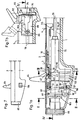
- the housing forms a handle for the device and is composed of a lower housing part 1 and an upper housing part 2. Both housing parts can be screwed together, or they are held together in the longitudinal direction by parallel pushing together with wedge locks, not shown, which ensure lateral guidance and at the same time Have detents when the upper and lower parts of the housing are arranged to cover one another.
- screw connections 3, 4, 5 can be provided in the side walls in accordance with the dash-dotted lines.
- guide tracks 8, 9 for slides 10, 11 are provided within the outer longitudinal side walls 6, 7. These slides 10, 11 are formed on the inside at their lower edge as racks 12, 13.
- a toothed wheel 14 meshes with these toothed racks, which is rotatably mounted in the lower housing part 1 on a pin 15 and ensures an exact opposite movement of the slides 10, 11.
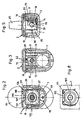
- the locking slide 16 is made in two parts and has a fork-like locking slide part 27 and a latching support 28 arranged at the same height, which are guided in the same longitudinal guide as the locking slide part in a direction parallel to the longitudinal axis of the housing. Between them, however, are arranged with their ends in recesses 29, 30 and 31, 32, respectively, springs 33, 34, which endeavor to press the two parts 27 and 28 apart.
- springs 33, 34 which endeavor to press the two parts 27 and 28 apart.
- a projection 38 is arranged on the locking slide, which according to FIG. 1 a has a step 39 downward and has two latching recesses 40, 41 at the end.
- a locking tooth 42 which is arranged on a cross slide 43.
- This cross slide 43 is guided by means of an elongated hole 44, in the extension thereof with respect to a pin 45 movable transversely to the longitudinal extent of the housing through a guide groove 47 in the latching support 28.
- the pin 45 On the locking bracket the pin 45 is also attached.
- the guide groove 47 is arranged transversely, in which a web 48 engages on the cross slide.
- there is free transverse mobility of the cross slide 43 the end position being dimensioned by stops between the inner edge of the elongated hole 44 on the one hand and the pin 45 on the other hand, so that in each end position the locking tooth 42 can engage in one of the locking recesses 40, 41.
- An actuating wedge 49 with equilateral flanks 62 is arranged centrally on the cross slide 43.
- This actuating wedge 49 is assigned a movable cam 50 which is pivotably mounted about a pivot pin 51. This is located on a bridge 52 fastened to the upper housing part 2.
- This movable cam has a wedge tip 53 which can be moved back and forth between two stops 54, 55 for dimensioning the largest deflection. Between these limit stops, a to-and-fro movement is effected on the one hand by a tension spring 56 which is fixed on the one hand to the bridge at 57 and on the other hand to the cam at 58 and is caused by a lever 59 which is pivotably mounted in the lower part (FIG. 1 a) is.
- This lever 59 is moved by the slide 10, which is guided in the housing on the other side, when this slide 10 is in its furthest left with respect to FIG. H. of syringe housing 25, is in the correct position.
- this slide 10 has a stop projection 115. It is in the stop position when the syringe plunger 116 is in its most advanced position in the syringe housing 25.
- the lever 59 is part of a U-shaped lever, which is pivotally mounted with a web 117 in bearing openings 118 of the lower housing part 1 (FIG. 1 a), the lever 59, which has an arm 114 on the cam 50 on the other Side than that on which the spring 56 acts, comes into engagement, on which the leg 60 of the U-shaped lever is arranged. With the leg 61 (FIG. 4 a) on the other side, the stop lug 115 comes into contact. This creates a movement transmission with simple means, which is also caused by the use of the two oppositely driven sliders 10, 11.
- the lever 59 is a continuation of the leg 60.
- This pivot lever arrangement 60, 61, 117 ensures that when the associated slide 10 is moved to the left with respect to FIGS. 1 and 6, the cam 50 is brought into the position shown in FIG. 6 under tension of the spring 56. If, in this initial position, the flank 62 of the cross slide 43 meets the flank 63 of the cam 50 after the locking slides 28 have been lifted from the locking slide 27 by relieving the tension springs 33, 34, the cross slide 43 is moved to the other side position. The locking tooth 42 is then aligned with the locking recess 41.
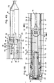
- an adjusting knob 65 is inserted with a cylindrical guide part 66 drawn into the interior of the housing, which is rotatably mounted in the pivot bearing 67, but axially not removable is.
- this cylindrical guide part 66 two longitudinal grooves 68, 69 are provided in the axial direction. In this longitudinal grooves engage the ends 70, 71 of a diagonal approach on a screw spindle 72 which leads out of the guide part and passes through a bore 74 provided with an internal thread 73 in a stroke limiting frame 75 which is fixedly arranged in the lower housing part.
- a guide block 80 which is axially movable in the housing Arranged, on which the slider 11 engages around an engaging projection 82 of the guide block 80 with a groove-like recess 81 directed towards the interior of the housing.
- the guide block 80 can always be moved back and forth with the slide 11, so that with respect to the syringe housing 25, a piston 116 movable in it, which is connected to the guide block 80 in a manner yet to be described, is moved back and forth.
- the guide block 80 has an insert receptacle 83 for a piston rod head 84, which is shown in broken lines in FIG. 4 b.
- a projection 85 projects into the insert receptacle, which has a U-shaped shape and is open at the top, and engages in an associated recess or groove in the piston rod head. Due to the U-shaped shape of the insert receptacle 83, the piston rod head 84 can be removed upwards.
- the guide block 80 also has a transversely arranged axis of rotation 86 for a pivot bolt 87 also shown in FIG. 1b, the handle of which is also shown in FIG. 5.
- This pivot bolt 87 includes the side block 88 from the outside of the guide block 80, and it has a downward projection 113 between the flanks, which presses on the piston rod head 84, which is enlarged relative to the piston rod of the syringe piston, and secures it in its position.
- the swivel bolt itself is held in its position by its side legs in elastic pressure and by side profiles.
- the upper part has an opening 89 which is open at the top and widens towards the end, the widened section 90 of which at the end permits the pivot bolt to be folded out.
- the adjoining, in contrast narrower, slit-like section 91 allows a tapered section 92 on the neck of the swivel lock 87 to move back with the operating movement of the piston rod, but without the tapered section 92 entering the narrower section 91 being able to fold out, as shown in FIG 1 b is shown in dashed lines.
- the swivel latch can only be brought into the open position when the syringe plunger is in its most inserted position into the syringe housing 25.
- the syringe plunger can be inserted or replaced in this position.
- the piston rod head 84 remains locked.
- the syringe housing 25 itself can be swung out of a U-shaped receptacle 93, the piston remaining on the housing. This is important if only the syringe housing 25 is to be replaced.
- the receptacle 93 is a U-shaped groove which is arranged in the lower housing part 1 and is open to the separating joint between the housing parts and into which the flange 95 of the syringe housing can be inserted.
- a pressure spring 94 which extends at least over the side flanks of the groove with bulging legs, is arranged on the wall, which is closer to the adjusting rotary knob. This ensures that the flange 95 of the syringe housing 25, which is inserted into the receptacle 93, is always held in a defined position in the wall 96 of the receptacle.
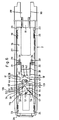
- a gear in particular a gear 97, is connected to the adjusting knob 65, in particular its cylindrical guide part 66, which meshes with a gear 98, which is arranged on a shaft 99, which is mounted in the lower housing part.
- a setting scale, counter or digital display with a number of dials 101, 102, 103 ... designated 100 as a whole, which are adjustable according to the decimal system.
- a window 104 shown in FIG. 7 is arranged in the lower housing part 1, the height extension of which makes only one digit visible on each dial, so that this window 104 also forms a pointer for this setting scale.
- a section of a side view of the lower housing part is drawn in FIG. 7. With the continuously variable setting of the syringe volume, the respective size can be seen in the window.
- an element of a movement brake 111 is arranged on the cylindrical guide part 66 according to FIG. 2 or FIG. 1a.
- This element is designed as a disk 105 which is rotatable with the cylindrical guide part 66.
- This circumferential disc 105 is assigned a brake bracket 106, which is fixedly arranged in the lower housing part.
- This brake bracket carries a weakly protruding locking tooth 107 on an elastically deflectable leg 108 of the brake bracket, and this locking tooth is assigned, according to FIG. 2, locking recesses 109, 110 on the disk.
- Fig. 8 which contains an individual representation, it can be seen that the disc 105 is circular at the exit and a corresponding concave brake shoe 112 is arranged on the elastic leg 108, so that an actually stepless adjustment is possible. This allows even finer subdivisions than mentioned above.
- the last dial of the setting scale 100 still has a subdivision in the area of each digit, so that the corresponding setting fractions can be read, with respect to to an edge of the window 104 marked as a pointer.
Landscapes
- Health & Medical Sciences (AREA)
- Clinical Laboratory Science (AREA)
- Chemical & Material Sciences (AREA)
- Chemical Kinetics & Catalysis (AREA)
- Infusion, Injection, And Reservoir Apparatuses (AREA)
- Rigid Pipes And Flexible Pipes (AREA)
- Devices For Use In Laboratory Experiments (AREA)
- Sampling And Sample Adjustment (AREA)
Priority Applications (1)
| Application Number | Priority Date | Filing Date | Title |
|---|---|---|---|
| AT83100409T ATE41110T1 (de) | 1982-02-06 | 1983-01-19 | Pipettiervorrichtung. |
Applications Claiming Priority (2)
| Application Number | Priority Date | Filing Date | Title |
|---|---|---|---|
| DE3204178A DE3204178C2 (de) | 1982-02-06 | 1982-02-06 | Pipettiervorrichtung |
| DE3204178 | 1982-02-06 |
Publications (3)
| Publication Number | Publication Date |
|---|---|
| EP0085854A2 EP0085854A2 (de) | 1983-08-17 |
| EP0085854A3 EP0085854A3 (en) | 1985-12-04 |
| EP0085854B1 true EP0085854B1 (de) | 1989-03-08 |
Family
ID=6155026
Family Applications (1)
| Application Number | Title | Priority Date | Filing Date |
|---|---|---|---|
| EP83100409A Expired EP0085854B1 (de) | 1982-02-06 | 1983-01-19 | Pipettiervorrichtung |
Country Status (6)
| Country | Link |
|---|---|
| US (1) | US4470317A (enExample) |
| EP (1) | EP0085854B1 (enExample) |
| JP (1) | JPS58189045A (enExample) |
| AT (1) | ATE41110T1 (enExample) |
| DE (1) | DE3204178C2 (enExample) |
| FI (1) | FI76006C (enExample) |
Cited By (1)
| Publication number | Priority date | Publication date | Assignee | Title |
|---|---|---|---|---|
| EP3928868A1 (de) | 2020-06-22 | 2021-12-29 | Eppendorf AG | Pipette für den gebrauch mit einer einen kolben und einen zylinder aufweisenden pipettenspitze oder spritze |
Families Citing this family (58)
| Publication number | Priority date | Publication date | Assignee | Title |
|---|---|---|---|---|
| US4539854A (en) * | 1983-10-13 | 1985-09-10 | Corning Glass Works | Friction drive for metering device |
| US4567780A (en) * | 1984-03-12 | 1986-02-04 | American Hospital Supply Corporation | Hand-held pipette with disposable capillary |
| US4681566A (en) * | 1984-11-30 | 1987-07-21 | Strato Medical Corporation | Infusion device |
| US4652260A (en) * | 1985-03-11 | 1987-03-24 | Strato Medical Corporation | Infusion device |
| US4627835A (en) * | 1985-03-11 | 1986-12-09 | Strato Medical Corporation | Tubing assembly for infusion device |
| US4710179A (en) * | 1986-10-27 | 1987-12-01 | Habley Medical Technology Corporation | Snap-on vernier syringe |
| GB8713810D0 (en) * | 1987-06-12 | 1987-07-15 | Hypoguard Uk Ltd | Measured dose dispensing device |
| US4973318A (en) * | 1988-02-10 | 1990-11-27 | D.C.P. Af 1988 A/S | Disposable syringe |
| EP0635277B1 (en) * | 1993-06-30 | 2001-11-21 | Hamilton Company, Inc. | Manual dispensing aid for a syringe |
| US5536249A (en) * | 1994-03-09 | 1996-07-16 | Visionary Medical Products, Inc. | Pen-type injector with a microprocessor and blood characteristic monitor |
| DE4414744C1 (de) * | 1994-04-27 | 1995-11-02 | Eppendorf Geraetebau Netheler | Repetierpipette |
| DE4414760C1 (de) * | 1994-04-27 | 1995-08-24 | Eppendorf Geraetebau Netheler | Repetierpipette |
| USD370974S (en) | 1995-01-27 | 1996-06-18 | Hamilton Company | Manual dispensing aid for a syringe |
| AU1860697A (en) * | 1995-09-08 | 1997-07-28 | Visionary Medical Products Corporation | Pen-type injector drive mechanism |
| JP2838070B2 (ja) * | 1996-03-07 | 1998-12-16 | 株式会社ニチリョー | 反復式ピペット |
| UA56256C2 (uk) | 1998-01-30 | 2003-05-15 | Ново Нордіск А/С | Шприц для ін'єкцій |
| RU2135286C1 (ru) * | 1998-10-27 | 1999-08-27 | Порядков Леонид Федорович | Пипетатор |
| US6143252A (en) * | 1999-04-12 | 2000-11-07 | The Perkin-Elmer Corporation | Pipetting device with pipette tip for solid phase reactions |
| TW453884B (en) | 1999-09-16 | 2001-09-11 | Novo Nordisk As | Dose setting limiter |
| US6663602B2 (en) * | 2000-06-16 | 2003-12-16 | Novo Nordisk A/S | Injection device |
| MXPA03008316A (es) | 2001-03-14 | 2004-09-10 | Penjet Corp | Metodo y sistema para remover gas disuelto de una solucion. |
| US6613010B2 (en) | 2001-04-13 | 2003-09-02 | Penjet Corporation | Modular gas-pressured needle-less injector |
| EP1427463A2 (en) | 2001-04-27 | 2004-06-16 | PenJet Corporation | Method and apparatus for filling or refilling a needle-less injector |
| JP4148894B2 (ja) | 2001-10-16 | 2008-09-10 | マトリックス・テクノロジイズ・コーポレーション | 手持ち式ピペット |
| US6824526B2 (en) | 2001-10-22 | 2004-11-30 | Penjet Corporation | Engine and diffuser for use with a needle-less injector |
| WO2003080160A1 (en) * | 2002-03-18 | 2003-10-02 | Eli Lilly And Company | Medication dispensing apparatus with gear set for mechanical advantage |
| US20060027033A1 (en) * | 2002-10-16 | 2006-02-09 | Richard Cote | Hand-held pipette employing voice recognition control |
| US7284454B2 (en) * | 2004-05-27 | 2007-10-23 | Matrix Technologies Corporation | Hand held pipette |
| US7018356B2 (en) | 2002-10-31 | 2006-03-28 | Wise Roger R | Method and apparatus for adjusting the contents of a needle-less injector |
| EP2210634A1 (en) * | 2009-01-22 | 2010-07-28 | Sanofi-Aventis Deutschland GmbH | Drug delivery device dose setting mechanism |
| GB0304822D0 (en) * | 2003-03-03 | 2003-04-09 | Dca Internat Ltd | Improvements in and relating to a pen-type injector |
| GB0308267D0 (en) * | 2003-04-10 | 2003-05-14 | Dca Design Int Ltd | Improvements in and relating to a pen-type injector |
| KR101121317B1 (ko) | 2003-08-12 | 2012-03-09 | 일라이 릴리 앤드 캄파니 | 기계적 확대율을 갖는 삼중 나사식 쓰레드를 갖는 약제투여 장치 |
| USD510629S1 (en) | 2004-01-16 | 2005-10-11 | Heathrow Scientific Llc | Pipette device with pivotable nozzle assembly |
| US7381371B2 (en) * | 2004-01-16 | 2008-06-03 | Heathrow Scientific Llc | Pipette device with pivotable nozzle assembly |
| ATE526052T1 (de) * | 2004-03-30 | 2011-10-15 | Lilly Co Eli | Medikationsabgabegerät mit getriebeset mit einer öffnung zur aufnahme eines antriebselements |
| EP1732629B1 (en) * | 2004-03-30 | 2019-04-24 | Eli Lilly And Company | Medication dispensing apparatus with spring-driven locking feature enabled by administration of final dose |
| PL1804865T3 (pl) | 2004-10-21 | 2010-03-31 | Novo Nordisk As | Mechanizm wkręcania dla nawijanych penów |
| US20080208142A1 (en) * | 2005-02-28 | 2008-08-28 | Novo Nordisk A/S | Dose Setting Mechanism for an Injection Device |
| US20090043264A1 (en) | 2005-04-24 | 2009-02-12 | Novo Nordisk A/S | Injection Device |
| JP5062768B2 (ja) | 2006-03-10 | 2012-10-31 | ノボ・ノルデイスク・エー/エス | 注射装置および該装置のカートリッジを交換する方法 |
| US8361036B2 (en) | 2006-03-10 | 2013-01-29 | Novo Nordisk A/S | Injection device having a gearing arrangement |
| US8226618B2 (en) | 2006-05-16 | 2012-07-24 | Novo Nordisk A/S | Gearing mechanism for an injection device |
| AU2007253481B2 (en) | 2006-05-18 | 2013-01-17 | Novo Nordisk A/S | An injection device with mode locking means |
| AU2008213084B2 (en) | 2007-02-05 | 2013-03-28 | Novo Nordisk A/S | Injection button |
| CA2681023C (en) | 2007-03-23 | 2015-11-03 | Novo Nordisk A/S | An injection device comprising a locking nut |
| US20090007701A1 (en) * | 2007-07-03 | 2009-01-08 | Hadjis Peter T | Pivoting pipette device |
| US20090010809A1 (en) * | 2007-07-03 | 2009-01-08 | Hadjis Peter T | Manual pipette filler |
| EP2797650A2 (en) | 2011-12-29 | 2014-11-05 | Novo Nordisk A/S | Torsion-spring based wind-up autoinjector pen with dial-up/dial-down dosing mechanism |
| PL2656915T3 (pl) * | 2012-04-23 | 2019-04-30 | Eppendorf Ag | Pipeta do uruchamiania strzykawki |
| EP2659978B1 (de) * | 2012-05-02 | 2017-06-28 | Eppendorf AG | Pipette mit Verriegelungssystem |
| US9295986B2 (en) | 2012-05-02 | 2016-03-29 | Eppendorf Ag | Pipette with releasable locking of rotational position of actuating element |
| PL227678B1 (pl) | 2015-12-22 | 2018-01-31 | Copernicus Spolka Z Ograniczona Odpowiedzialnoscia | Układ sterująco-napędowy dla urządzenia do iniekcji oraz urządzenie do iniekcji zaopatrzone w taki układ |
| PL3108914T3 (pl) | 2016-07-07 | 2019-08-30 | Copernicus Sp. Z O.O. | Urządzenie wstrzykujące do podawania określonej liczby jednakowych dawek substancji płynnej |
| US9950855B1 (en) | 2017-02-20 | 2018-04-24 | Neogen Corporation | Dispenser having a sub-assembly for selectively engaging and disengaging a plunger rod |
| PL232651B1 (pl) | 2017-07-18 | 2019-07-31 | Copernicus Spolka Z Ograniczona Odpowiedzialnoscia | Sprzęgło z systemem blokowania dla medycznego urządzenia wstrzykującego |
| EP3474820B1 (en) | 2017-08-24 | 2024-02-07 | Novo Nordisk A/S | Glp-1 compositions and uses thereof |
| PE20230819A1 (es) | 2020-02-18 | 2023-05-19 | Novo Nordisk As | Composiciones y usos de glp-1 |
Family Cites Families (8)
| Publication number | Priority date | Publication date | Assignee | Title |
|---|---|---|---|---|
| US3831602A (en) * | 1972-02-11 | 1974-08-27 | Union Plastics Corp | Adjustable syringe assemblies |
| US3827305A (en) * | 1972-10-24 | 1974-08-06 | R Gilson | Adjustable pipette |
| DE2926691C2 (de) * | 1979-07-02 | 1983-05-26 | Eppendorf Gerätebau Netheler + Hinz GmbH, 2000 Hamburg | Repetierpipette |
| US4086062A (en) * | 1977-02-23 | 1978-04-25 | Hach Chemical Company | Digital titration device |
| SE7702086L (sv) * | 1977-02-25 | 1978-08-26 | Lkb Produkter Ab | Handpipett |
| DE2812729A1 (de) * | 1978-03-23 | 1979-09-27 | Michael Becker | Injektionsvorrichtung zur intramuskulaeren einspritzung, vornehmlich von insulin |
| FI60137C (fi) * | 1979-03-23 | 1981-12-10 | Suovaniemi Finnpipette | Pipett |
| FI58875C (fi) * | 1979-08-31 | 1981-05-11 | Suovaniemi Finnpipette | Pipett |
-
1982
- 1982-02-06 DE DE3204178A patent/DE3204178C2/de not_active Expired
-
1983
- 1983-01-18 FI FI830157A patent/FI76006C/fi not_active IP Right Cessation
- 1983-01-19 AT AT83100409T patent/ATE41110T1/de not_active IP Right Cessation
- 1983-01-19 EP EP83100409A patent/EP0085854B1/de not_active Expired
- 1983-01-27 US US06/461,483 patent/US4470317A/en not_active Expired - Lifetime
- 1983-02-04 JP JP58016296A patent/JPS58189045A/ja active Granted
Cited By (3)
| Publication number | Priority date | Publication date | Assignee | Title |
|---|---|---|---|---|
| EP3928868A1 (de) | 2020-06-22 | 2021-12-29 | Eppendorf AG | Pipette für den gebrauch mit einer einen kolben und einen zylinder aufweisenden pipettenspitze oder spritze |
| US11951471B2 (en) | 2020-06-22 | 2024-04-09 | Eppendorf Ag | Pipette for use with a pipette tip or syringe having a piston and a cylinder |
| EP4406655A3 (de) * | 2020-06-22 | 2024-08-21 | Eppendorf SE | Pipette für den gebrauch mit einer einen kolben und einen zylinder aufweisenden pipettenspitze oder spritze |
Also Published As
| Publication number | Publication date |
|---|---|
| EP0085854A2 (de) | 1983-08-17 |
| FI830157A0 (fi) | 1983-01-18 |
| DE3204178C2 (de) | 1986-03-20 |
| EP0085854A3 (en) | 1985-12-04 |
| US4470317A (en) | 1984-09-11 |
| JPH0153103B2 (enExample) | 1989-11-13 |
| JPS58189045A (ja) | 1983-11-04 |
| DE3204178A1 (de) | 1983-08-18 |
| FI830157L (fi) | 1983-08-07 |
| FI76006B (fi) | 1988-05-31 |
| FI76006C (fi) | 1988-09-09 |
| ATE41110T1 (de) | 1989-03-15 |
Similar Documents
| Publication | Publication Date | Title |
|---|---|---|
| EP0085854B1 (de) | Pipettiervorrichtung | |
| EP0187613B1 (de) | Ratchenschlüssel | |
| DE2546299B2 (de) | Eichfähige Pipette | |
| DE3408090C2 (enExample) | ||
| DE3027736C2 (de) | Fokussiermechanismus für ein Fernglas | |
| DE2821635C2 (de) | Hubvorrichtung | |
| DE2400366C2 (de) | Haarschneidegerät mit einem Klingenhalter für eine zweischneidige Klinge | |
| DE3825269A1 (de) | Kurbelmechanismus fuer einen hebe-schiebedeckel eines kraftfahrzeugs | |
| DE1210308B (de) | Zickzacknaehmaschine mit einem durch eine Steuerscheibe oder ein Handstellmittel wahlweise einstellbaren Stichstellglied | |
| DE1477827A1 (de) | Vorschubgetriebe fuer Werkzeugmaschinen | |
| DE1275910B (de) | Getriebe eines Treibstangenbeschlages fuer Fenster, Tueren od. dgl., insbesondere fuer Kipp-Schwenkfluegel-Fenster | |
| EP0419421A1 (de) | Uhr mit einer geradlinigen Skala | |
| DE1272161B (de) | Getriebe eines Treibstangenbeschlages fuer Fenster, Tueren od. dgl., insbesondere fuer Kipp-Schwenkfluegel-Fenster | |
| DE3836683C1 (en) | Compass with adjustment spindle, especially rapid-adjustment compass | |
| DE954112C (de) | Vorrichtung zum Ein- und Ausschalten von Bewegungsvogaengen, insbesondere fuer Getriebe landwirtschaftlicher Maschinen | |
| DE3507331C2 (enExample) | ||
| DE1772587C (de) | Schwenkbarer Gerätegriff | |
| DE231400C (enExample) | ||
| DE2353420C2 (de) | Vorrichtung zum Betatigen zweier je einem Getriebe od.dgl. zugeordneter Schalthebel | |
| DE713496C (de) | Steuervorrichtung an Zaehlwerken fuer Schreibrechenmaschinen u. dgl. | |
| DE2250802A1 (de) | Pneumatische zeitsteuervorrichtung | |
| DE1582926C3 (de) | Druckwechsler von Melkmaschinen | |
| DE726843C (de) | Schalteinrichtung fuer Stufengetriebe | |
| DE19600637A1 (de) | Fahrrad-Gangwahlmechanismus | |
| DE2854466C2 (de) | Zeichenkopf für Zeichenmaschinen |
Legal Events
| Date | Code | Title | Description |
|---|---|---|---|
| PUAI | Public reference made under article 153(3) epc to a published international application that has entered the european phase |
Free format text: ORIGINAL CODE: 0009012 |
|
| AK | Designated contracting states |
Designated state(s): AT BE CH FR GB IT LI LU NL SE |
|
| 17P | Request for examination filed |
Effective date: 19840128 |
|
| PUAL | Search report despatched |
Free format text: ORIGINAL CODE: 0009013 |
|
| AK | Designated contracting states |
Designated state(s): AT BE CH FR GB IT LI LU NL SE |
|
| 17Q | First examination report despatched |
Effective date: 19870820 |
|
| RAP1 | Party data changed (applicant data changed or rights of an application transferred) |
Owner name: EPPENDORF-NETHELER-HINZ GMBH |
|
| GRAA | (expected) grant |
Free format text: ORIGINAL CODE: 0009210 |
|
| AK | Designated contracting states |
Kind code of ref document: B1 Designated state(s): AT BE CH FR GB IT LI LU NL SE |
|
| REF | Corresponds to: |
Ref document number: 41110 Country of ref document: AT Date of ref document: 19890315 Kind code of ref document: T |
|
| ET | Fr: translation filed | ||
| GBT | Gb: translation of ep patent filed (gb section 77(6)(a)/1977) | ||
| ITF | It: translation for a ep patent filed | ||
| PLBE | No opposition filed within time limit |
Free format text: ORIGINAL CODE: 0009261 |
|
| STAA | Information on the status of an ep patent application or granted ep patent |
Free format text: STATUS: NO OPPOSITION FILED WITHIN TIME LIMIT |
|
| 26N | No opposition filed | ||
| ITTA | It: last paid annual fee | ||
| EPTA | Lu: last paid annual fee | ||
| EAL | Se: european patent in force in sweden |
Ref document number: 83100409.8 |
|
| PGFP | Annual fee paid to national office [announced via postgrant information from national office to epo] |
Ref country code: FR Payment date: 20001211 Year of fee payment: 19 Ref country code: AT Payment date: 20001211 Year of fee payment: 19 |
|
| PGFP | Annual fee paid to national office [announced via postgrant information from national office to epo] |
Ref country code: SE Payment date: 20001218 Year of fee payment: 19 Ref country code: GB Payment date: 20001218 Year of fee payment: 19 |
|
| PGFP | Annual fee paid to national office [announced via postgrant information from national office to epo] |
Ref country code: CH Payment date: 20001220 Year of fee payment: 19 |
|
| PGFP | Annual fee paid to national office [announced via postgrant information from national office to epo] |
Ref country code: NL Payment date: 20001222 Year of fee payment: 19 |
|
| PGFP | Annual fee paid to national office [announced via postgrant information from national office to epo] |
Ref country code: BE Payment date: 20010105 Year of fee payment: 19 |
|
| PGFP | Annual fee paid to national office [announced via postgrant information from national office to epo] |
Ref country code: LU Payment date: 20010131 Year of fee payment: 19 |
|
| REG | Reference to a national code |
Ref country code: CH Ref legal event code: PFA Free format text: EPPENDORF-NETHELER-HINZ GMBH TRANSFER- EPPENDORF AG |
|
| REG | Reference to a national code |
Ref country code: FR Ref legal event code: CJ Ref country code: FR Ref legal event code: CD |
|
| REG | Reference to a national code |
Ref country code: GB Ref legal event code: IF02 |
|
| PG25 | Lapsed in a contracting state [announced via postgrant information from national office to epo] |
Ref country code: LU Free format text: LAPSE BECAUSE OF NON-PAYMENT OF DUE FEES Effective date: 20020119 Ref country code: GB Free format text: LAPSE BECAUSE OF NON-PAYMENT OF DUE FEES Effective date: 20020119 Ref country code: AT Free format text: LAPSE BECAUSE OF NON-PAYMENT OF DUE FEES Effective date: 20020119 |
|
| PG25 | Lapsed in a contracting state [announced via postgrant information from national office to epo] |
Ref country code: SE Free format text: LAPSE BECAUSE OF NON-PAYMENT OF DUE FEES Effective date: 20020120 |
|
| PG25 | Lapsed in a contracting state [announced via postgrant information from national office to epo] |
Ref country code: LI Free format text: LAPSE BECAUSE OF NON-PAYMENT OF DUE FEES Effective date: 20020131 Ref country code: CH Free format text: LAPSE BECAUSE OF NON-PAYMENT OF DUE FEES Effective date: 20020131 Ref country code: BE Free format text: LAPSE BECAUSE OF NON-PAYMENT OF DUE FEES Effective date: 20020131 |
|
| BERE | Be: lapsed |
Owner name: EPPENDORF A.G. Effective date: 20020131 |
|
| PG25 | Lapsed in a contracting state [announced via postgrant information from national office to epo] |
Ref country code: NL Free format text: LAPSE BECAUSE OF NON-PAYMENT OF DUE FEES Effective date: 20020801 |
|
| EUG | Se: european patent has lapsed |
Ref document number: 83100409.8 |
|
| GBPC | Gb: european patent ceased through non-payment of renewal fee |
Effective date: 20020119 |
|
| REG | Reference to a national code |
Ref country code: CH Ref legal event code: PL |
|
| PG25 | Lapsed in a contracting state [announced via postgrant information from national office to epo] |
Ref country code: FR Free format text: LAPSE BECAUSE OF NON-PAYMENT OF DUE FEES Effective date: 20020930 |
|
| NLV4 | Nl: lapsed or anulled due to non-payment of the annual fee |
Effective date: 20020801 |
|
| REG | Reference to a national code |
Ref country code: FR Ref legal event code: ST |