EP0080291A2 - Système de suspension à régulation optimale par computer, comportant la combinaison amortisseur-ressort à air - Google Patents
Système de suspension à régulation optimale par computer, comportant la combinaison amortisseur-ressort à air Download PDFInfo
- Publication number
- EP0080291A2 EP0080291A2 EP82305897A EP82305897A EP0080291A2 EP 0080291 A2 EP0080291 A2 EP 0080291A2 EP 82305897 A EP82305897 A EP 82305897A EP 82305897 A EP82305897 A EP 82305897A EP 0080291 A2 EP0080291 A2 EP 0080291A2
- Authority
- EP
- European Patent Office
- Prior art keywords
- pressure
- shock absorber
- air
- chamber
- compression
- Prior art date
- Legal status (The legal status is an assumption and is not a legal conclusion. Google has not performed a legal analysis and makes no representation as to the accuracy of the status listed.)
- Granted
Links
Images


Classifications
-
- B—PERFORMING OPERATIONS; TRANSPORTING
- B60—VEHICLES IN GENERAL
- B60G—VEHICLE SUSPENSION ARRANGEMENTS
- B60G17/00—Resilient suspensions having means for adjusting the spring or vibration-damper characteristics, for regulating the distance between a supporting surface and a sprung part of vehicle or for locking suspension during use to meet varying vehicular or surface conditions, e.g. due to speed or load
- B60G17/015—Resilient suspensions having means for adjusting the spring or vibration-damper characteristics, for regulating the distance between a supporting surface and a sprung part of vehicle or for locking suspension during use to meet varying vehicular or surface conditions, e.g. due to speed or load the regulating means comprising electric or electronic elements
- B60G17/0152—Resilient suspensions having means for adjusting the spring or vibration-damper characteristics, for regulating the distance between a supporting surface and a sprung part of vehicle or for locking suspension during use to meet varying vehicular or surface conditions, e.g. due to speed or load the regulating means comprising electric or electronic elements characterised by the action on a particular type of suspension unit
- B60G17/0155—Resilient suspensions having means for adjusting the spring or vibration-damper characteristics, for regulating the distance between a supporting surface and a sprung part of vehicle or for locking suspension during use to meet varying vehicular or surface conditions, e.g. due to speed or load the regulating means comprising electric or electronic elements characterised by the action on a particular type of suspension unit pneumatic unit
-
- B—PERFORMING OPERATIONS; TRANSPORTING
- B60—VEHICLES IN GENERAL
- B60G—VEHICLE SUSPENSION ARRANGEMENTS
- B60G2202/00—Indexing codes relating to the type of spring, damper or actuator
- B60G2202/10—Type of spring
- B60G2202/15—Fluid spring
- B60G2202/152—Pneumatic spring
-
- B—PERFORMING OPERATIONS; TRANSPORTING
- B60—VEHICLES IN GENERAL
- B60G—VEHICLE SUSPENSION ARRANGEMENTS
- B60G2202/00—Indexing codes relating to the type of spring, damper or actuator
- B60G2202/20—Type of damper
- B60G2202/24—Fluid damper
-
- B—PERFORMING OPERATIONS; TRANSPORTING
- B60—VEHICLES IN GENERAL
- B60G—VEHICLE SUSPENSION ARRANGEMENTS
- B60G2400/00—Indexing codes relating to detected, measured or calculated conditions or factors
- B60G2400/25—Stroke; Height; Displacement
- B60G2400/252—Stroke; Height; Displacement vertical
-
- B—PERFORMING OPERATIONS; TRANSPORTING
- B60—VEHICLES IN GENERAL
- B60G—VEHICLE SUSPENSION ARRANGEMENTS
- B60G2400/00—Indexing codes relating to detected, measured or calculated conditions or factors
- B60G2400/50—Pressure
- B60G2400/51—Pressure in suspension unit
- B60G2400/512—Pressure in suspension unit in spring
- B60G2400/5122—Fluid spring
- B60G2400/51222—Pneumatic
-
- B—PERFORMING OPERATIONS; TRANSPORTING
- B60—VEHICLES IN GENERAL
- B60G—VEHICLE SUSPENSION ARRANGEMENTS
- B60G2500/00—Indexing codes relating to the regulated action or device
- B60G2500/10—Damping action or damper
-
- B—PERFORMING OPERATIONS; TRANSPORTING
- B60—VEHICLES IN GENERAL
- B60G—VEHICLE SUSPENSION ARRANGEMENTS
- B60G2500/00—Indexing codes relating to the regulated action or device
- B60G2500/20—Spring action or springs
- B60G2500/22—Spring constant
-
- B—PERFORMING OPERATIONS; TRANSPORTING
- B60—VEHICLES IN GENERAL
- B60G—VEHICLE SUSPENSION ARRANGEMENTS
- B60G2500/00—Indexing codes relating to the regulated action or device
- B60G2500/30—Height or ground clearance
-
- B—PERFORMING OPERATIONS; TRANSPORTING
- B60—VEHICLES IN GENERAL
- B60G—VEHICLE SUSPENSION ARRANGEMENTS
- B60G2600/00—Indexing codes relating to particular elements, systems or processes used on suspension systems or suspension control systems
- B60G2600/18—Automatic control means
- B60G2600/182—Active control means
-
- B—PERFORMING OPERATIONS; TRANSPORTING
- B60—VEHICLES IN GENERAL
- B60G—VEHICLE SUSPENSION ARRANGEMENTS
- B60G2600/00—Indexing codes relating to particular elements, systems or processes used on suspension systems or suspension control systems
- B60G2600/22—Magnetic elements
- B60G2600/26—Electromagnets; Solenoids
Definitions
- the present invention relates to a shock absorber system and to vehicle suspension systems including such a system more particularly the invention in its preferred form is directed to a vehicle suspension system in which a computer controls damping and spring forces to optimize ride and handling characteristics under a wide range of driving conditions.
- Vehicle suspension systems have heretofore included shock absorbers, springs (coil,leaf, air or torsion bar), axle housings, torque arms, A-frames, anti-roll bars, stabilizers, and so forth. These components have been assembled in various combinations to produce the desired ride and handling characteristics of the vehicle.
- springs coil,leaf, air or torsion bar
- axle housings torque arms
- A-frames anti-roll bars
- stabilizers stabilizers
- shock absorbers dissipate the energy stored in the springs by gradually forcing oil through orifices and valves.
- the flow resistance encountered by the oil results in compression and rebound forces which control the spring movement.
- the work done by the oil as it moves through the valves converts energy stored in the springs into heat which is dissipated from the shock absorbers into the surrounding air.
- the amount of force exerted by a spring- is proportional to how far it is deflected.
- the amount of force exerted by a hydraulic shock absorber is proportional to the velocity of the piston therein.
- Modern hydraulic shock absorbers include, for example, a six-stage valve system (three compression stages and three rebound stages) to provide optimum control at various piston velocities.
- the goal in a conventional suspension system is to match the resistance or control force of the shock absorbers to the forces generated by their corresponding springs in a manner that will yield the desired ride and handling characteristics.
- the control forces which conventional shock absorbers exhibit during compression and rebound are determined by their particular bleed valves, blow-off valves, spring discs, blow-off springs or piston restrictions, -etc. -
- the damping--curves (force versus piston velocity) of conventional shock absorbers are predetermined - by their construction and are not adjusted during vehicle travel.
- U. S. Patent Numbers 2,967,062; 2,993,705; and 3,608,925 disclose systems for controlling the roll of a vehicle, for example, during a turn.
- U. S. Patent No. 3,995,883 discloses a vehicle suspension system in which a wheel-to-body-displacement transducer and an acceleration transducer on the vehicle body produce signals which are utilized to vary the damping forces in the system.
- U. S. Patent No. 4,065,154 discloses a vehicle suspension system in which signals from a plurality of wheel axle velocity transducers are utilized in varying the damping forces.
- British Patent No. 1,522,795 discloses a vehicle suspension system in which an electrically actuable spool valve controls the application of fluid pressure to a damping control valve.
- An object of the present invention is to provide an improved shock absorber system which, when incorporated in a vehicle suspension system, will automatically adjust itself during vehicle travel to provide optimum ride and handling characteristics under a wide variety of driving conditions.
- a shock absorber system comprising: a damping chamber including a quantity of hydraulic fluid and a piston dividing the chamber into first and second. portions; hydraulic sensor means in communication with the chamber for sensing the position of the piston within the chamber; and
- hydraulic fluid regulator means for adjusting the pressure of the hydraulic fluid in the first and second chamber portions responsive to movement of the piston within the chamber whereby the compression and rebound damping forces of the shock absorber system may be controlled.
- the invention also includes a suspension system for a vehicle having a sprung portion including a frame and an unsprung portion including a wheel, comprising:
- the compression and rebound damping of the shock absorber may be varied independently.
- a combined shock absorber/air spring unit is connected between the wheel and frame of a vehicle.
- the shock absorber includes a hydraulic sensor which provides signals to a computer which are representative of the position of the piston within the shock absorber.
- the computer utilizes these signals to control compression and rebound hydraulic pressure regulators to produce preprogrammed compression and rebound damping forces that will yield the desired ride and handling.
- the air spring may be connected in series with the shock absorber for compression and rebound along the same axis. Pressure sensors and air pressure inlet and outlet valves are connected to the computer for adjusting the pressure within the air spring to provide the desired spring rate.
- the computer can be programmed so that the vehicle will provide an extremely smooth ride on level highways. Simultaneously, the computer may also be programmed so that only limited roll and pitch will be experienced during cornering and/or braking while bumps encountered during cornering and/or braking will be cushioned significantly. Computer programming may also simultaneously provide the vehicle with good off-road handling. Automatic load leveling may also be achieved. In summary, virtually any suspension characteristics can be achieved by appropriate programming. Thus, the suspension system for a given vehicle may provide an optimum set of ride and handling characteristics.
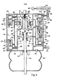
- a wheel 10 is rotatably mounted on an axle 11 which extends from one end of a carrier 12.
- the other end of the carrier is pivotally mounted to the frame or body 14 of the vehicle.
- a suspension unit 16 is connected between the frame 14 and the axle 11.
- the unit 16 combines an upper shock absorber 18 and a lower air spring 20.
- the wheel, axle and carrier thus comprise the unsprung portion-of the vehicle and the frame and body comprise the sprung portion of the vehicle.
- the damping forces of the shock absorber 18 and the forces exerted by the air spring 20 are varied by a control circuit 22 in order to optimize the ride and handling characteristics of the vehicle under the wide range of driving conditions.
- the shock absorber 18 and the air spring 20 of the suspension unit are arranged in series for simultaneous compression and rebound along the same longitudinal axis as the wheel of the vehicle moves up and down with-respect to the frame.
- the shock absorber piston-. rod 24 extends axially through the center of the air spring 20 and is connected to the axle of the wheel.
- the air spring is made of a flexible bellow.
- a connecting member 26 extends from the upper end of the shock absorber 18 and is attached to the vehicle frame.
- An 'air tight cylindrical housing 28 concentrically surrounds the shock absorber 18.
- air flows between the interiors of the air spring and the cylindrical housing 28 through a vent hole 30 in the base 32 of the housing. This air flow helps dissipate heat from the shock absorber 18.
- the size of the vent hole and air space in the housing 28 will affect the spring constant of the air spring 20. Hydraulic fluid may be filled or drained from the shock absorber 18 by removing a fill plug 34 which normally seals a passage that extends from the shock absorber through the base 32 of the housing.
- a hydraulic compression pressure regulator 36 and a hydraulic rebound regulator 38 are mounted within the housing 28 ( Figure 2). Also mounted within the housing 28 are an air pressure inlet valve 40 and an air pressure outlet valve 42. An air inlet nipple 44 and an electrical connection jack 46 are provided on an upper cap 48 of the housing. An air outlet nipple 50 is provided on the base 32 of the housing 28. A resilient bump stop 25 is provided to protect the suspension on severe bumps.
- the shock absorber 18 includes an inner cylinder 52 and an outer cylinder 54 which surrounds the inner cylinder and defines a reservoir 56.
- a main piston 58 is connected to the upper end of the piston rod 24 and reciprocates longitudinally within the inner cylinder 52.
- the piston 58 divides the inner cylinder 52 into an upper chamber 60 and a lower chamber 62.
- the inner cylinder 52 and the reservoir 56 of, the shock absorber and all passages and chambers connected thereto are filled with a quantity of hydraulic fluid. There is no gas in contact with or in the fluid.
- the piston 58 is slidable along the upper end of the piston rod 24 between a-pair of fixed flanges 64 and 66.
- the piston 58- is centered between the flanges by springs 68 and 70.
- This resilient mounting of the main piston 58 relative to the piston rod 24 cushions any abrupt stops or starts of the piston, thereby eliminating the need for bleed valves in the main piston which are found in conventional shock absorbers. No fluid is intentionally allowed to pass between chambers 60 and 62 through piston - 58.
- the shock absorber 18 is further provided with a compression amplifying valve 72 which is mounted above the upper chamber 60.
- the function of the valve 72 is described hereafter in greater detail. It includes a central flanged spool 74 and an outer flanged spool 76 which reciprocates about the inner flange spool. The reciprocation of the flanged spools is limited by springs 78, 79 and 80.
- a hydraulic sensor 82 communicates with the reservoir 56 of the shock absorber.
- the hydraulic sensor 82 is not visible in Figure 2 It-includes a piston 84 ( Figure 3) which is moved by fluctuations in the amount of hydraulic fluid within the cylinder 52 due to the volume occupied by the piston rod 24.
- the hydraulic sensor 82 also includes a transducer such as a linear variable differential transformer 86. This transducer generates signals representative of the position of the piston 84 and therefore the position of the main piston 58.
- the compression and rebound pressure regulators 36 and 38 may each comprise linear servo solenoid actuated valves. Signals may be applied to these solenoids to adjust the threshold blow off pressure required to open the passages 37 and 37' held closed by the solenoid pistons 84''and 84". This provides a pressure regulator whereby predetermined : pressures within chambers 61 and 62 can be selected by valves 36 and 38, respectively. Fluid flow will be blocked until pressure reaches the preselected threshold pressure, at which time the valve opens and attempts to maintain that pressure.
- the air pressure inlet and outlet valves 40 and 42 may each comprise solenoid actuated valves. Signals may be applied to these solenoids to meter the flow of air therethrough.
- the various passages such as 88 and 90 which connect the valves of the aforementioned regulators to their fluid inputs and outputs are formed in the base 32 and cap 48 ( Figure 2) of the cylindrical housing 28.
- the leads such as 92 of the various solenoids are connected to the control circuit 22 via electrical connector 46.
- the control circuit applies signals to the solenoids of the regulators 36 and 38 to independently adjust the pressure of the hydraulic fluid in the upper chamber 61 and in the lower chamber 62 to provide predetermined compression and rebound damping forces.
- the pressure in chamber 61 sets the threshold pressure in chamber 60 by way of the pressure amplifying valve 72 to be described later.
- the function of the air pressure inlet and outlet valves 40 and 42 is to adjust the air pressure within the air spring- 20.
- the control circuit applies signals to the . solenoids of these valves to meter the flow of air into and out of the housing 28. This also adjusts the air pressure within the air spring 20 since the air can flow from within the housing 28 and into the air spring through the vent hole 30.
- the air pressure inlet valve 40 is connected to a pressurized: gas source, such as an accumulator 94 which is in turn connected to a pump 96.
- a pipe 98 connects the accumulator with the inlet nipple 44. This nipple communicates with the valve 40 through a passage 100 in the cap 48.
- Air pressure sensors 99 and 101 generate signals representative of the air pressure within the accumulator 94 and the air spring 20, respectively.
- the outlet orifice 102 of the valve 40 communicates with the interior of the housing.
- the inlet orifice 104 of the air pressure outlet valve 42 also communicates with the interior of the housing 28.
- the passage 90 formed in the base 32 of the housing connects the outlet of the regulator 42 to the outlet nipple 50.
- the passage 98 communicates the air pressure in accumulator 94 with all of the suspension units associated with the different wheels of the vehicle.
- Hydraulic fluid completely fills-the chambers 60 and 62 as well as the reservoir 56, the valves of the regulators 36 and 38 and the passages leading to and from these valves. Hydraulic fluid also fills the passage 106 leading to the hydraulic sensor 82.
- the cases of the sensor 82 and valves 36 and 38 have vent holes 108 to permit -the pressurized air which is within the air spring 20 and the housing 28 to act on one side of the pistons 84, 84' and 84".
- the hydraulic fluid acts on the other side of the pistons. In this way, the shock absorber adds to the spring rate of the air spring due to its pressure on the fluid within the shock absorber.
- the hydraulic sensor 82 provides signals to the control circuit indicating the position of the main piston 58 within the shock absorber.
- the control circuit uses this position information to adjust the regulators 36 and 38 as necessary to achieve predetermined compression and rebound damping forces.
- hydraulic fluid is pumped from the upper chamber 60 of the shock' absorber, through the amplifying valve 72 via passage 114 or 115 or both, and the valve of the regulator 36 and into the reservoir 56.
- hydraulic fluid from the reservoir is drawn through the check valves 111 and into the lower chamber 62 of the shock absorber.
- the amount of fluid which is pumped from the upper chamber 60 and the amount of fluid which is pumped into the lower chamber 62 during compression is not equal. This is because of the volume occupied by the portion of the piston rod 24 which is progressively inserted into the lower chamber 62 during compression.
- the extra hydraulic fluid moves the piston 84 of the sensor--downwardly.
- the compression pressure regulator 36 cannot adequately control exceedingly low compression forces which may be required in the upper chamber 60, because the orifice 37 is too small for the amount of fluid that must flow from chamber 60 into reservoir 56 during rapid movement of piston 58. Therefore, the compression amplifying valve 72 enables low compression damping forces to be generated, by providing sufficient orifice size for large flow rates at low compression damping forces, as may be desired. In addition, exceedingly high compression forces can be provided by the compression amplifying valve at all flow rates.
- the compression amplifying valve 72 operates as- follows. As the piston 58 starts to move upward, the pressure of the hydraulic fluid within the chamber 60 increases. Spring-79 keeps spool 74 against orifice 115 for a minimum pressure in chamber 60. Hydraulic fluid is forced through an orifice 114 and check-valve 116 in the flanged spool 74 into the upper chamber portion 61. The pressure within the chamber 61 is adjusted by the compression pressure regulator 36. If the pressure in chamber 61 is minimal, the flanged spool 76 rests against the seat 117, and flanged spool 74 rests against the seat 112. As the velocity of the main piston 58 increases, pressure builds up against the flange of-the spool 74. The spring 79 determines the blow-off force required to displace the flanged spool 74 upwardly. As the flanged spool 74 blows off, the spring 80 is compressed.
- the flanged spool 76 is pushed downwardly against the springs 78 and 80.
- the force which pushes the flanged spool 76 downwardly is significantly greater than the force which pushes the flanged spool 74 upwardly, if chambers 60 and 61 are at similar pressure. This is because the area of the flange, of the spool_ 76 is significantly greater than that of the spool 74.
- the rebound pressure regulator doesn't require the amplifying valve because the rebound speeds are more consistent since they deal primarily with the natural frequency of the unsprung mass. This can be adequately controlled by selection of the fixed size of passage 39 in combination with the variable threshold pressure set by pressure regulator 38.
- the control circuit 22 simultaneously controls all of the suspension units associated with the different wheels of the vehicle.
- the circuit includes a computer 118 such as a microprocessor having suitable 'RAM and ROM memories connected thereto for storing computation information and an operational program, respectively.
- the computer 118 has input ports 120 connected thereto for receiving signals from various transducers within the suspension units. These include the piston position sensors or transducers 82 on each suspension unit, the air pressure sensor 99 and the air pressure sensor 101 on some or all of the suspension units.
- a signal source 122 may be connected to the input of the transducer and the output of the transducer is connected to a detector 124.
- Analog to digital converters 126 convert the analog signals from the transducers in the suspension unit into digital form before they are input to the computer 118 through the input ports.
- the microprocessor uses the operational program stored in the ROM of the computer 118 to determine the optimum compression and rebound damping forces as well as the optimum spring rate. Commands are sent from the computer 118 to control the pump 96, air pressure inlet and outlet regulators 40 and 42 on some or all of the suspension units, and the compression and rebound regulators 36 and 38 on each suspension unit.
- Output ports 128 provide the interface between the computer 118 and the devices which it controls.
- Digitally controlled switches 130 are utilized to turn the air pump 96 on and off and to open and close the air pressure valves.
- Digital-to-analog converters 131, current sources 132 and an optional high voltage supply 134 are utilized to generate the signals necessary to control the hydraulic compression and rebound pressure regulators 36 and 38.
- Figure 5 illustrates the simplest possible electrically controllable! :shock absorber.
- the shock absorber 200 is that of any conventional design.
- the variation is that the first stage valving or "bleed orificing" in the piston is set for very rapid pressure build up for improved roll control and performance.
- a solenoid pressure regulator valve 220 of the preferred embodiment is connected between the compression chamber via conduit 230 and the rebound chamber via conduit 240.
- a control circuit 210 can set the initial first stage blow-off pressure on compression to any level from very low pressure for soft control to very high pressure for stiff control. This is accomplished by allowing the valve 220 to bypass the fluid flow around the first stage orificing within the shock absorber 200 upon compression.
- Figure 6 illustrates a variation that is capable of much higher performance.
- the fluid pressure in chamber 61 is obtained by fluid flow through passage 114 due to the bias pressure generated by the action of spring 79 on spool 74. This flow is limited for soft ride characteristics. If chamber 61 is isolated from the fluid in the shock absorber and connected to an external fluid pressure supply as shown in Figure 6, then faster response can be obtained.
- the shock absorber 300 is that shown in Figure 3 only spring 79 is removed and passage 114 is blocked.
- Passage 88 in Figure 3 is connected to passage 350 in Figure 6.
- Passage 89 in Figure 3 is connected to passage 355 in Figure 6.
- the operation of the system illustrated in Figure 6 is as follows.
- blow-off pressure of spool 74 in Figure 3 is still set by the pressure in chamber 61 of Figure-3.
- the fluid pressure in- chamber 61 of Figure 3 is set by valve 36 with the fluid-flow into chamber 61 provided through passage 350 from a high pressure fluid accumulation 320 in Figure 6.
- the return fluid flow from valve 36 in Figure 3 goes 'to a fluid reservoir 330.
- a pump 310 is then connected between accumulator 320 and reservoir 330 via passages 340 and 345 to recharge the accumulator 320.
- the amplifying valve can have spring 80 removed and spools 74 and 76 attached as one one unit.
- the main blow-off orifice 115 would normally be open.
Landscapes
- Engineering & Computer Science (AREA)
- Mechanical Engineering (AREA)
- Vehicle Body Suspensions (AREA)
Applications Claiming Priority (4)
| Application Number | Priority Date | Filing Date | Title |
|---|---|---|---|
| US32220081A | 1981-11-17 | 1981-11-17 | |
| US322200 | 1981-11-17 | ||
| US06/352,239 US4468739A (en) | 1981-11-17 | 1982-02-25 | Computer optimized adaptive suspension system having combined shock absorber/air spring unit |
| US352239 | 1999-07-13 |
Publications (3)
| Publication Number | Publication Date |
|---|---|
| EP0080291A2 true EP0080291A2 (fr) | 1983-06-01 |
| EP0080291A3 EP0080291A3 (en) | 1984-07-04 |
| EP0080291B1 EP0080291B1 (fr) | 1987-06-10 |
Family
ID=26983308
Family Applications (1)
| Application Number | Title | Priority Date | Filing Date |
|---|---|---|---|
| EP82305897A Expired EP0080291B1 (fr) | 1981-11-17 | 1982-11-05 | Système de suspension à régulation optimale par computer, comportant la combinaison amortisseur-ressort à air |
Country Status (3)
| Country | Link |
|---|---|
| US (1) | US4468739A (fr) |
| EP (1) | EP0080291B1 (fr) |
| DE (1) | DE3276527D1 (fr) |
Cited By (19)
| Publication number | Priority date | Publication date | Assignee | Title |
|---|---|---|---|---|
| DE3403649A1 (de) * | 1983-02-02 | 1984-08-02 | Mitsubishi Jidosha Kogyo K.K., Tokio/Tokyo | Radaufhaengungssystem fuer automobile und andere fahrzeuge |
| GB2135020A (en) * | 1983-02-03 | 1984-08-22 | Mitsubishi Motors Corp | Vehicle suspension unit with damping and spring rate adjustable in response to suspension extension |
| EP0133589A2 (fr) * | 1983-08-15 | 1985-02-27 | Lonnie K. Woods | Système de suspension à régulation optimale par ordinateur |
| EP0139144A1 (fr) * | 1983-08-25 | 1985-05-02 | Mitsubishi Denki Kabushiki Kaisha | Suspension pour automobiles |
| EP0157181A1 (fr) * | 1984-02-29 | 1985-10-09 | Nissan Motor Co., Ltd. | Système de commande de suspension pour véhicule avec une caractéristique d'amortissement dépendant des conditions de route |
| EP0162818A1 (fr) * | 1984-05-11 | 1985-11-27 | FIAT AUTO S.p.A. | Dispositif pour le réglage d'amortisseurs de suspension, particulièrement pour véhicules à moteur |
| DE3517624A1 (de) * | 1984-08-25 | 1986-03-06 | Toyota Jidosha K.K., Toyota, Aichi | Verfahren zur fahrzeughoehenregulierung |
| GB2164725A (en) * | 1984-09-21 | 1986-03-26 | Freudenberg Carl | Pneumatic suspension device |
| FR2573701A1 (fr) * | 1984-11-29 | 1986-05-30 | Toyota Motor Co Ltd | Suspension pneumatique |
| US4613116A (en) * | 1984-11-28 | 1986-09-23 | Toyota Jidosha Kabushiki Kaisha | Air suspension |
| US4677599A (en) * | 1984-06-20 | 1987-06-30 | Nissan Motor Company, Limited | Ultra-sonic distance measuring apparatus and method |
| US4686626A (en) * | 1983-09-17 | 1987-08-11 | Nissan Motor Company, Ltd. | Pitching-suppressive control system and method for an automotive vehicle suspension |
| EP0275664A1 (fr) * | 1986-12-22 | 1988-07-27 | Lord Corporation | Dispositif de commande à observateur pour des systèmes de suspension ou similaires |
| US4796911A (en) * | 1983-09-09 | 1989-01-10 | Nissan Motor Company, Ltd. | Automotive suspension system with roll-stabilizer having road condition-dependent torsion modulus, and control of torsional modules |
| EP0305382A1 (fr) * | 1987-03-18 | 1989-03-08 | Monroe Auto Equipment Co | Procede et appareil amortisseurs de chocs mecaniques. |
| US4827416A (en) * | 1985-09-13 | 1989-05-02 | Nissan Motor Company, Limited | Method and system for controlling automotive suspension system, particularly for controlling suspension characteristics in accordance with road surface conditions |
| EP0339180A2 (fr) * | 1988-04-25 | 1989-11-02 | Firma Carl Freudenberg | Ressort à gaz sous pression |
| GB2491450A (en) * | 2011-05-31 | 2012-12-05 | Gm Global Tech Operations Inc | A method for calibrating an adaptive chassis system of a motorvehicle |
| CN113239450A (zh) * | 2021-03-11 | 2021-08-10 | 华南理工大学 | 一种基于区间分析的互联空气悬架多目标优化方法 |
Families Citing this family (78)
| Publication number | Priority date | Publication date | Assignee | Title |
|---|---|---|---|---|
| US4544154A (en) * | 1978-10-13 | 1985-10-01 | Pepsico, Inc. | Passive programmable resistance device |
| FR2497896A1 (fr) * | 1980-08-29 | 1982-07-16 | Messier Hispano Sa | Amortisseur |
| US4722548A (en) * | 1981-11-17 | 1988-02-02 | Hamilton James M | Computer optimized adaptive suspension system having combined shock absorber/air spring unit |
| EP0104871B1 (fr) * | 1982-09-21 | 1987-07-08 | Fujitsu Limited | Dispositif de support |
| JPS59137207A (ja) * | 1983-01-24 | 1984-08-07 | Nissan Motor Co Ltd | サスペンシヨン装置 |
| JPS59120612U (ja) * | 1983-02-02 | 1984-08-14 | 三菱自動車工業株式会社 | 車両用サスペンシヨン装置 |
| US4586728A (en) * | 1983-02-28 | 1986-05-06 | Mazda Motor Corporation | Vehicle suspension means having variable suspension characteristics |
| DE3308011C2 (de) * | 1983-03-07 | 1985-02-14 | Daimler-Benz Ag, 7000 Stuttgart | Aktives Federungssystem |
| JPS59186713A (ja) * | 1983-03-18 | 1984-10-23 | Mazda Motor Corp | 自動車のサスペンシヨン |
| DE3329327A1 (de) * | 1983-08-13 | 1985-02-28 | Fa. Carl Freudenberg, 6940 Weinheim | Gasdruckfeder |
| US4634142A (en) * | 1983-08-15 | 1987-01-06 | C & K Venture Income I-Coast | Computer optimized adaptive suspension system |
| JPS6047709A (ja) * | 1983-08-24 | 1985-03-15 | Mitsubishi Motors Corp | 自動車の懸架装置 |
| AU553238B2 (en) * | 1983-09-26 | 1986-07-10 | Nhk Spring Co. Ltd. | Vehicle hydropneumatic suspension |
| JPS60105213U (ja) * | 1983-12-23 | 1985-07-18 | トヨタ自動車株式会社 | サスペンシヨンの緩衝力調節機構 |
| JPS60105215U (ja) * | 1983-12-24 | 1985-07-18 | トヨタ自動車株式会社 | サスペンシヨンの緩衝力調節機構 |
| DE3579351D1 (de) * | 1984-04-30 | 1990-10-04 | Gold Henning | Pneumatische feder-daempfer-einheit. |
| GB8411319D0 (en) * | 1984-05-03 | 1984-06-06 | Armstrong Patents Co Ltd | Shock absorbers |
| US4783089A (en) * | 1984-10-15 | 1988-11-08 | C & K Venture Income I-Coast | Air spring control system and method |
| JPS61163009A (ja) * | 1985-01-14 | 1986-07-23 | Toyota Motor Corp | 車両 |
| GB8503290D0 (en) * | 1985-02-08 | 1985-03-13 | Lotus Car | Vehicle suspension arrangements |
| SE447926B (sv) * | 1985-05-13 | 1986-12-22 | Jan R Schnittger | Hydraulisk stotdempare der dempformagan paverkas av ett styrorgan |
| JPS61287808A (ja) * | 1985-06-14 | 1986-12-18 | Nissan Motor Co Ltd | 車両のサスペンシヨン制御装置 |
| JPH0613246B2 (ja) * | 1985-10-01 | 1994-02-23 | トヨタ自動車株式会社 | サスペンション制御装置 |
| US4744589A (en) * | 1985-10-01 | 1988-05-17 | Toyota Jidosha Kabushiki Kaisha | Suspension control system |
| JPH07446B2 (ja) * | 1985-10-26 | 1995-01-11 | トヨタ自動車株式会社 | サスペンシヨン制御装置 |
| JPH06104450B2 (ja) * | 1986-01-29 | 1994-12-21 | 財団法人鉄道総合技術研究所 | 車両の振動制御装置 |
| JPH0737203B2 (ja) * | 1986-05-08 | 1995-04-26 | 日産自動車株式会社 | 車高制御装置 |
| IT209827Z2 (it) * | 1987-01-16 | 1988-11-04 | Itt Ind Riunite Srl | Dispositivo a trasformatore per il rilevamento del livello di veicoli. |
| US4838392A (en) * | 1987-08-05 | 1989-06-13 | Lord Corporation | Semi-active damper for vehicles and the like |
| US4763959A (en) * | 1987-10-23 | 1988-08-16 | Allied-Signal Inc. | Electronic control for fluid pressure braking system |
| US5053671A (en) * | 1987-11-16 | 1991-10-01 | Nissan Motor Company, Limited | Piezoelectric sensor for monitoring kinetic momentum |
| US4907680A (en) * | 1988-01-29 | 1990-03-13 | Lord Corporation | Semi-active damper piston valve assembly |
| US4878691A (en) * | 1988-03-23 | 1989-11-07 | Dbx Corporation | Trailer suspension apparatus |
| US4953089A (en) * | 1988-05-09 | 1990-08-28 | Lord Corporation | Hybrid analog digital control method and apparatus for estimation of absolute velocity in active suspension systems |
| US4887699A (en) * | 1989-02-10 | 1989-12-19 | Lord Corporation | Vibration attenuating method utilizing continuously variable semiactive damper |
| US4921272A (en) * | 1989-02-10 | 1990-05-01 | Lord Corporation | Semi-active damper valve means with electromagnetically movable discs in the piston |
| US4936425A (en) * | 1989-02-10 | 1990-06-26 | Lord Corporation | Method of operating a vibration attenuating system having semiactive damper means |
| US5004079A (en) * | 1989-02-10 | 1991-04-02 | Lord Corporation | Semi-active damper valve means and method |
| US4993523A (en) * | 1989-02-10 | 1991-02-19 | Lord Corporation | Fluid circuit for semiactive damper means |
| US5016912A (en) * | 1989-02-22 | 1991-05-21 | Dbx Corporation | Trailer suspension apparatus |
| US4934733A (en) * | 1989-02-22 | 1990-06-19 | Dbx Corporation | Trailer suspension apparatus |
| US5147018A (en) * | 1989-03-02 | 1992-09-15 | Kajima Corporation | Cylinder lock device for use in structure |
| US4898264A (en) * | 1989-04-03 | 1990-02-06 | Lord Corporation | Semiactive damper with motion responsive valve means |
| GB8910277D0 (en) * | 1989-05-04 | 1989-06-21 | Lotus Group Plc | Land vehicle suspension control system |
| JPH03277792A (ja) * | 1990-02-01 | 1991-12-09 | Kobe Steel Ltd | 振動表面処理方法および振動表面処理装置 |
| US5044455A (en) * | 1990-02-16 | 1991-09-03 | Navistar International Transportion Corp. | Actively controlled truck cab suspension |
| US5475596A (en) * | 1991-05-20 | 1995-12-12 | General Motors Corporation | Full car semi-active suspension control based on quarter car control |
| US5434782A (en) * | 1991-05-20 | 1995-07-18 | General Motors Corporation | Suspension system state observer |
| DE4136104A1 (de) * | 1991-11-02 | 1993-05-06 | Fichtel & Sachs Ag, 8720 Schweinfurt, De | Verfahren zur lastabhaengigen beeinflussung eines federnden und daempfenden abstuetzsystems zwischen fahrwerk und aufbau eines fahrzeugs und abstuetzsystems zur durchfuehrung dieses verfahrens |
| US5529152A (en) * | 1994-07-08 | 1996-06-25 | Aimrite Systems International, Inc. | Variable constant force hydraulic components and systems |
| US5570288A (en) * | 1995-03-27 | 1996-10-29 | General Motors Corporation | Vehicle suspension control using a scaled wheel demand force |
| US5606503A (en) * | 1995-03-27 | 1997-02-25 | General Motors Corporation | Suspension system control responsive to ambient temperature |
| US5559700A (en) * | 1995-03-27 | 1996-09-24 | General Motors Corporation | Continuously variable damping system |
| US5570289A (en) * | 1995-03-27 | 1996-10-29 | General Motors Corporation | Vehicle suspension control with wheel and body demand force phase determination |
| JP3769326B2 (ja) * | 1996-07-15 | 2006-04-26 | 東洋ゴム工業株式会社 | アクティブ型除振装置 |
| WO2000028236A1 (fr) | 1998-11-11 | 2000-05-18 | Kenmar Company Trust | Systeme adaptatif de suspension optimise par ordinateur et methode correspondante |
| US6418360B1 (en) * | 1999-01-08 | 2002-07-09 | Shockware | Sensor structure for measuring vehicle suspension related information |
| US6378878B1 (en) * | 1999-09-28 | 2002-04-30 | Navistar International Transportation Corp. | Self-leveling suspension system |
| US20060237242A1 (en) * | 2000-09-25 | 2006-10-26 | Burke Robert J | Lightweight surface vehicle |
| DE60139273D1 (de) * | 2000-09-25 | 2009-08-27 | Its Bus Inc | Platformen für ausdauernden transport |
| US20040111707A1 (en) * | 2000-12-15 | 2004-06-10 | Bliss Andrew L. | Debugger for multiple processors and multiple debugging types |
| US6752250B2 (en) * | 2001-09-27 | 2004-06-22 | Northrop Grumman Corporation | Shock, vibration and acoustic isolation system |
| WO2004018242A2 (fr) * | 2002-08-21 | 2004-03-04 | Delphi Technologies, Inc. | Systeme de suspension reglable pour cabine de conduite de camion |
| AU2003262787A1 (en) * | 2002-08-21 | 2004-03-11 | Delphi Technologies, Inc. | Controlled truck cab suspension |
| DE10252961A1 (de) * | 2002-11-14 | 2004-05-27 | Daimlerchrysler Ag | Verfahren und Sensoranordnung zur Regelung und/oder Steuerung eines aktiven und/oder steuerbaren Fahrwerks |
| WO2005039900A2 (fr) | 2003-10-24 | 2005-05-06 | Aloha, Llc | Suspensions pour véhicules à plancher surbaissé |
| JP2005282696A (ja) * | 2004-03-29 | 2005-10-13 | Canon Inc | 除振マウント装置、露光装置及びデバイス製造方法 |
| US8490952B1 (en) * | 2004-07-23 | 2013-07-23 | Vibroacoustics Solutions, Inc. | Continuously variable natural frequency and damping vibration isolation system |
| US7220253B2 (en) * | 2004-12-02 | 2007-05-22 | Chek-Med Systems, Inc. | Gastrojejunal feeding tube |
| US7416189B2 (en) * | 2005-02-17 | 2008-08-26 | Spartan Motors Chassis, Inc. | Vehicle ride control system |
| JP2009188053A (ja) * | 2008-02-04 | 2009-08-20 | Canon Inc | 露光装置およびデバイス製造方法 |
| US8172237B2 (en) * | 2009-04-03 | 2012-05-08 | Arvinmeritor Technology, Llc | Active suspension and adaptive damping configuration |
| US20110057371A1 (en) | 2009-09-01 | 2011-03-10 | Parto Rezania | Suspension Mechanism |
| US8682532B2 (en) | 2011-07-22 | 2014-03-25 | Honda Motor Co., Ltd. | Vehicle including friction control device and methods |
| US9145038B2 (en) * | 2011-08-31 | 2015-09-29 | Bombardier Recreational Products Inc. | Vehicle suspension and pneumatic systems |
| US10053109B2 (en) | 2016-02-26 | 2018-08-21 | Honda Motor Co., Ltd. | Systems and methods for controlling a vehicle including friction control device |
| US11498383B2 (en) * | 2020-02-13 | 2022-11-15 | GM Global Technology Operations LLC | Continuously variable rate fluid spring system for a vehicle, and method of operation |
| US20230073413A1 (en) * | 2021-09-06 | 2023-03-09 | Wheel Pros, Llc | Coil Replacement Load Leveling System with Safe Height Feature. |
Citations (12)
| Publication number | Priority date | Publication date | Assignee | Title |
|---|---|---|---|---|
| FR1079482A (fr) * | 1953-06-22 | 1954-11-30 | Amortisseur hydraulique, à double effet, auto-régulateur, à freinage de suspension, variable et automatique, agissant en fonction de la vitesse et du rayon de braquage du véhicule ou par commande sélective à main | |
| US2893104A (en) * | 1957-05-23 | 1959-07-07 | Gen Motors Corp | Air suspension |
| US3035853A (en) * | 1958-12-10 | 1962-05-22 | Itt | Vehicle suspension and stabilizing system |
| US3720425A (en) * | 1969-08-05 | 1973-03-13 | Aisin Seiki | Process and apparatus for the adjustment of the height of the chassis of a wheeled vehicle |
| FR2173364A5 (fr) * | 1972-02-21 | 1973-10-05 | Allinquant Fernand | |
| US3807678A (en) * | 1972-09-19 | 1974-04-30 | Lord Corp | System for controlling the transmission of energy between spaced members |
| US3819166A (en) * | 1972-10-12 | 1974-06-25 | Gen Motors Corp | Gas bladder for combination liquid gas suspension device |
| NL7316435A (en) * | 1973-11-30 | 1975-06-03 | Kuipers James Berend | Movement damping system - exerts damping force proportional to speed of movement |
| US4065154A (en) * | 1975-06-07 | 1977-12-27 | Lucas Industries Limited | Vehicle suspension systems |
| FR2386427A1 (fr) * | 1977-04-09 | 1978-11-03 | Messerschmitt Boelkow Blohm | Jambe elastique, en particulier pour trains d'atterrissage d'avions |
| GB2012913A (en) * | 1978-01-20 | 1979-08-01 | Girling Ltd | Gas Spring |
| GB1604416A (en) * | 1978-05-30 | 1981-12-09 | Lucas Industries Ltd | Vehicle suspension system |
Family Cites Families (27)
| Publication number | Priority date | Publication date | Assignee | Title |
|---|---|---|---|---|
| US3124368A (en) * | 1964-03-10 | Electronic controlled vehicle suspension system | ||
| FR828820A (fr) * | 1937-02-04 | 1938-05-31 | Perfectionnements aux dispositifs de stabilisation des véhicules | |
| US2973969A (en) * | 1955-05-11 | 1961-03-07 | Earle S Thall | Electrical shock absorbing system |
| US2967062A (en) * | 1956-08-30 | 1961-01-03 | Avigdor Leslie B D | Sway and pitch control apparatus for vehicles |
| US2993705A (en) * | 1958-08-18 | 1961-07-25 | Avigdor Leslie B D | Electropneumatic sway control apparatus for land vehicles |
| US3321210A (en) * | 1966-04-12 | 1967-05-23 | Frederick J Harding | Electrically controlled shock absorber system |
| DE1629716C3 (de) * | 1967-09-29 | 1983-06-01 | Benteler-Werke Ag Werk Neuhaus, 4790 Paderborn | Verfahren und Vorrichtung zum kontinuierlichen Aufbringen einer wärme- und schallisolierenden Mantelschicht auf ein Metallrohr |
| US3502347A (en) * | 1967-11-06 | 1970-03-24 | Itt | Apparatus for vehicle suspension control |
| DE1755087C2 (de) * | 1968-03-28 | 1975-11-27 | Boge Gmbh, 5208 Eitorf | Elektronisch gesteuerte Niveauregelvorrichtung für druckmittelgespeiste Federungen, insbesondere von Kraftfahrzeugen |
| US3574352A (en) * | 1969-04-17 | 1971-04-13 | Gen Motors Corp | Automatic vehicle leveling system having electronic pressure switch control |
| US3608925A (en) * | 1969-05-07 | 1971-09-28 | Peter H Murphy | Apparatus for offsetting centrifugal force affecting motor vehicles |
| DE1944178A1 (de) * | 1969-08-30 | 1971-03-11 | Bosch Gmbh Robert | Niveauregeleinrichtung |
| DE2124542A1 (de) * | 1971-05-18 | 1972-11-30 | Hoesch Ag, 4600 Dortmund | Steuerelektronik für Niveauregeleinrichtungen, insbesondere für Kraftfahrzeuge |
| US3727941A (en) * | 1971-12-08 | 1973-04-17 | Gen Motors Corp | Automobile levelizer control unit |
| BE810148A (fr) * | 1973-01-30 | 1974-07-25 | Montage de commande electronique destine a des regulateurs de niveau | |
| JPS506017A (fr) * | 1973-05-21 | 1975-01-22 | ||
| US3995883A (en) * | 1973-11-21 | 1976-12-07 | Lucas Aerospace Limited | Land vehicle wheel suspension arrangements |
| GB1522795A (en) * | 1974-08-15 | 1978-08-31 | Lucas Industries Ltd | Damping device for a vehicle suspension |
| US4017099A (en) * | 1975-06-09 | 1977-04-12 | Monroe Auto Equipment Company | Vehicle leveling system |
| CA1071738A (fr) * | 1975-11-25 | 1980-02-12 | Paul J. Long (Jr.) | Circuit de nivellement de vehicules automobiles |
| US4054295A (en) * | 1976-08-16 | 1977-10-18 | General Motors Corporation | Vehicle body support and leveler device |
| DE2646547A1 (de) * | 1976-10-15 | 1978-04-20 | Bosch Gmbh Robert | Niveauregeleinrichtung fuer kraftfahrzeuge |
| US4084830A (en) * | 1977-04-04 | 1978-04-18 | Daniel Jr James A | Levelling and stabilization system for a vehicle |
| DE2716476C2 (de) * | 1977-04-14 | 1985-07-11 | Robert Bosch Gmbh, 7000 Stuttgart | Niveauregeleinrichtung für Kraftfahrzeuge |
| GB1600390A (en) * | 1977-10-25 | 1981-10-14 | British Railways Board | Active suspensions for vehicles |
| US4164664A (en) * | 1977-12-13 | 1979-08-14 | Kasiewicz Stanley Joseph | Control circuit for load-leveling shock absorbers |
| US4168840A (en) * | 1978-03-24 | 1979-09-25 | General Motors Corporation | Motor vehicle level control circuit |
-
1982
- 1982-02-25 US US06/352,239 patent/US4468739A/en not_active Expired - Fee Related
- 1982-11-05 EP EP82305897A patent/EP0080291B1/fr not_active Expired
- 1982-11-05 DE DE8282305897T patent/DE3276527D1/de not_active Expired
Patent Citations (12)
| Publication number | Priority date | Publication date | Assignee | Title |
|---|---|---|---|---|
| FR1079482A (fr) * | 1953-06-22 | 1954-11-30 | Amortisseur hydraulique, à double effet, auto-régulateur, à freinage de suspension, variable et automatique, agissant en fonction de la vitesse et du rayon de braquage du véhicule ou par commande sélective à main | |
| US2893104A (en) * | 1957-05-23 | 1959-07-07 | Gen Motors Corp | Air suspension |
| US3035853A (en) * | 1958-12-10 | 1962-05-22 | Itt | Vehicle suspension and stabilizing system |
| US3720425A (en) * | 1969-08-05 | 1973-03-13 | Aisin Seiki | Process and apparatus for the adjustment of the height of the chassis of a wheeled vehicle |
| FR2173364A5 (fr) * | 1972-02-21 | 1973-10-05 | Allinquant Fernand | |
| US3807678A (en) * | 1972-09-19 | 1974-04-30 | Lord Corp | System for controlling the transmission of energy between spaced members |
| US3819166A (en) * | 1972-10-12 | 1974-06-25 | Gen Motors Corp | Gas bladder for combination liquid gas suspension device |
| NL7316435A (en) * | 1973-11-30 | 1975-06-03 | Kuipers James Berend | Movement damping system - exerts damping force proportional to speed of movement |
| US4065154A (en) * | 1975-06-07 | 1977-12-27 | Lucas Industries Limited | Vehicle suspension systems |
| FR2386427A1 (fr) * | 1977-04-09 | 1978-11-03 | Messerschmitt Boelkow Blohm | Jambe elastique, en particulier pour trains d'atterrissage d'avions |
| GB2012913A (en) * | 1978-01-20 | 1979-08-01 | Girling Ltd | Gas Spring |
| GB1604416A (en) * | 1978-05-30 | 1981-12-09 | Lucas Industries Ltd | Vehicle suspension system |
Cited By (26)
| Publication number | Priority date | Publication date | Assignee | Title |
|---|---|---|---|---|
| DE3403649A1 (de) * | 1983-02-02 | 1984-08-02 | Mitsubishi Jidosha Kogyo K.K., Tokio/Tokyo | Radaufhaengungssystem fuer automobile und andere fahrzeuge |
| GB2135020A (en) * | 1983-02-03 | 1984-08-22 | Mitsubishi Motors Corp | Vehicle suspension unit with damping and spring rate adjustable in response to suspension extension |
| EP0133589A2 (fr) * | 1983-08-15 | 1985-02-27 | Lonnie K. Woods | Système de suspension à régulation optimale par ordinateur |
| EP0133589A3 (en) * | 1983-08-15 | 1986-12-17 | Lonnie K. Woods | Computer optimized adaptive suspension system |
| US4624478A (en) * | 1983-08-25 | 1986-11-25 | Mitsubishi Denki Kabushiki Kaisha | Suspension device for automobile |
| EP0139144A1 (fr) * | 1983-08-25 | 1985-05-02 | Mitsubishi Denki Kabushiki Kaisha | Suspension pour automobiles |
| US4796911A (en) * | 1983-09-09 | 1989-01-10 | Nissan Motor Company, Ltd. | Automotive suspension system with roll-stabilizer having road condition-dependent torsion modulus, and control of torsional modules |
| US4686626A (en) * | 1983-09-17 | 1987-08-11 | Nissan Motor Company, Ltd. | Pitching-suppressive control system and method for an automotive vehicle suspension |
| EP0157181A1 (fr) * | 1984-02-29 | 1985-10-09 | Nissan Motor Co., Ltd. | Système de commande de suspension pour véhicule avec une caractéristique d'amortissement dépendant des conditions de route |
| EP0162818A1 (fr) * | 1984-05-11 | 1985-11-27 | FIAT AUTO S.p.A. | Dispositif pour le réglage d'amortisseurs de suspension, particulièrement pour véhicules à moteur |
| US4677599A (en) * | 1984-06-20 | 1987-06-30 | Nissan Motor Company, Limited | Ultra-sonic distance measuring apparatus and method |
| DE3517624A1 (de) * | 1984-08-25 | 1986-03-06 | Toyota Jidosha K.K., Toyota, Aichi | Verfahren zur fahrzeughoehenregulierung |
| DE3434660A1 (de) * | 1984-09-21 | 1986-04-03 | Fa. Carl Freudenberg, 6940 Weinheim | Luftfeder |
| FR2570784A1 (fr) * | 1984-09-21 | 1986-03-28 | Freudenberg Carl | Amortisseur pneumatique |
| GB2164725A (en) * | 1984-09-21 | 1986-03-26 | Freudenberg Carl | Pneumatic suspension device |
| US4613116A (en) * | 1984-11-28 | 1986-09-23 | Toyota Jidosha Kabushiki Kaisha | Air suspension |
| FR2573701A1 (fr) * | 1984-11-29 | 1986-05-30 | Toyota Motor Co Ltd | Suspension pneumatique |
| US4827416A (en) * | 1985-09-13 | 1989-05-02 | Nissan Motor Company, Limited | Method and system for controlling automotive suspension system, particularly for controlling suspension characteristics in accordance with road surface conditions |
| EP0275664A1 (fr) * | 1986-12-22 | 1988-07-27 | Lord Corporation | Dispositif de commande à observateur pour des systèmes de suspension ou similaires |
| EP0305382A1 (fr) * | 1987-03-18 | 1989-03-08 | Monroe Auto Equipment Co | Procede et appareil amortisseurs de chocs mecaniques. |
| EP0305382A4 (en) * | 1987-03-18 | 1991-05-15 | Monroe Auto Equipment Company | Method and apparatus for absorbing mechanical shock |
| EP0339180A2 (fr) * | 1988-04-25 | 1989-11-02 | Firma Carl Freudenberg | Ressort à gaz sous pression |
| EP0339180A3 (en) * | 1988-04-25 | 1990-03-21 | Firma Carl Freudenberg | Air pressure spring |
| GB2491450A (en) * | 2011-05-31 | 2012-12-05 | Gm Global Tech Operations Inc | A method for calibrating an adaptive chassis system of a motorvehicle |
| US8775021B2 (en) | 2011-05-31 | 2014-07-08 | GM Global Technology Operations LLC | Method for calibrating an adaptive chassis system |
| CN113239450A (zh) * | 2021-03-11 | 2021-08-10 | 华南理工大学 | 一种基于区间分析的互联空气悬架多目标优化方法 |
Also Published As
| Publication number | Publication date |
|---|---|
| EP0080291A3 (en) | 1984-07-04 |
| DE3276527D1 (en) | 1987-07-16 |
| EP0080291B1 (fr) | 1987-06-10 |
| US4468739A (en) | 1984-08-28 |
Similar Documents
| Publication | Publication Date | Title |
|---|---|---|
| US4468739A (en) | Computer optimized adaptive suspension system having combined shock absorber/air spring unit | |
| US4722548A (en) | Computer optimized adaptive suspension system having combined shock absorber/air spring unit | |
| US4468050A (en) | Computer optimized adaptive suspension system | |
| US4634142A (en) | Computer optimized adaptive suspension system | |
| US4465299A (en) | Vehicle suspension with load-controlled damping and load-controlled damper | |
| US5682980A (en) | Active suspension system | |
| EP0305382B1 (fr) | Procede et appareil amortisseurs de chocs mecaniques | |
| US4896752A (en) | Vehicle strut | |
| JP3467002B2 (ja) | 懸架減衰装置 | |
| US3124368A (en) | Electronic controlled vehicle suspension system | |
| US6450304B1 (en) | Piston and rod assembly for air-actuated variable damping | |
| US5586781A (en) | Variable ride height vehicle suspension system | |
| US4798398A (en) | Dual rate equalizer suspension | |
| GB2350411A (en) | A damper for a vehicle suspension with an externally mounted semi-active system | |
| US4872702A (en) | Suspension system for vehicles | |
| US4900056A (en) | Hydraulic cylinder assembly for automotive suspension system and actively controlled suspension system utilizing same | |
| JPS61235210A (ja) | 車両用懸架システム | |
| US4619467A (en) | Variable rate air spring apparatus for vehicle suspension | |
| JPS61261118A (ja) | 車両用懸架機構 | |
| US5163659A (en) | Hydraulic actuator for leveling system | |
| EP0397702B1 (fr) | Amortisseur a regime variable et systeme a cet effet | |
| JPS58110311A (ja) | シヨツクアブソ−バ空気スプリングユニツトの組合せを有したコンピユ−タ最適化サスペンシヨンシステム | |
| US2992836A (en) | Fluid pressure spring for vehicle suspension and control apparatus therefor | |
| EP0975478A1 (fr) | Ameliorations de systemes de suspensions de vehicules | |
| CA1228612A (fr) | Systeme de suspension, a combinaison d'amortisseur et de ressort pneumatique, a reaction reglee par micro-processeur |
Legal Events
| Date | Code | Title | Description |
|---|---|---|---|
| PUAI | Public reference made under article 153(3) epc to a published international application that has entered the european phase |
Free format text: ORIGINAL CODE: 0009012 |
|
| AK | Designated contracting states |
Designated state(s): BE DE FR GB IT SE |
|
| PUAL | Search report despatched |
Free format text: ORIGINAL CODE: 0009013 |
|
| AK | Designated contracting states |
Designated state(s): BE DE FR GB IT SE |
|
| 17P | Request for examination filed |
Effective date: 19841224 |
|
| GRAA | (expected) grant |
Free format text: ORIGINAL CODE: 0009210 |
|
| AK | Designated contracting states |
Kind code of ref document: B1 Designated state(s): BE DE FR GB IT SE |
|
| REF | Corresponds to: |
Ref document number: 3276527 Country of ref document: DE Date of ref document: 19870716 |
|
| ET | Fr: translation filed | ||
| ITF | It: translation for a ep patent filed |
Owner name: UFFICIO BREVETTI RICCARDI & C. |
|
| PLBE | No opposition filed within time limit |
Free format text: ORIGINAL CODE: 0009261 |
|
| STAA | Information on the status of an ep patent application or granted ep patent |
Free format text: STATUS: NO OPPOSITION FILED WITHIN TIME LIMIT |
|
| 26N | No opposition filed | ||
| ITTA | It: last paid annual fee | ||
| PGFP | Annual fee paid to national office [announced via postgrant information from national office to epo] |
Ref country code: FR Payment date: 19901212 Year of fee payment: 9 |
|
| PGFP | Annual fee paid to national office [announced via postgrant information from national office to epo] |
Ref country code: DE Payment date: 19901217 Year of fee payment: 9 |
|
| PGFP | Annual fee paid to national office [announced via postgrant information from national office to epo] |
Ref country code: SE Payment date: 19901219 Year of fee payment: 9 |
|
| PGFP | Annual fee paid to national office [announced via postgrant information from national office to epo] |
Ref country code: BE Payment date: 19901227 Year of fee payment: 9 |
|
| PGFP | Annual fee paid to national office [announced via postgrant information from national office to epo] |
Ref country code: GB Payment date: 19910102 Year of fee payment: 9 |
|
| REG | Reference to a national code |
Ref country code: FR Ref legal event code: ST |
|
| PG25 | Lapsed in a contracting state [announced via postgrant information from national office to epo] |
Ref country code: GB Effective date: 19911105 |
|
| PG25 | Lapsed in a contracting state [announced via postgrant information from national office to epo] |
Ref country code: SE Effective date: 19911106 |
|
| PG25 | Lapsed in a contracting state [announced via postgrant information from national office to epo] |
Ref country code: BE Effective date: 19911130 |
|
| REG | Reference to a national code |
Ref country code: FR Ref legal event code: DA |
|
| BERE | Be: lapsed |
Owner name: HAMILTON JAMES M. Effective date: 19911130 Owner name: WOODS LONNIE K. Effective date: 19911130 |
|
| GBPC | Gb: european patent ceased through non-payment of renewal fee | ||
| PG25 | Lapsed in a contracting state [announced via postgrant information from national office to epo] |
Ref country code: DE Effective date: 19920801 |
|
| PG25 | Lapsed in a contracting state [announced via postgrant information from national office to epo] |
Ref country code: FR Free format text: LAPSE BECAUSE OF NON-PAYMENT OF DUE FEES Effective date: 19930730 |
|
| REG | Reference to a national code |
Ref country code: FR Ref legal event code: ST |
|
| EUG | Se: european patent has lapsed |
Ref document number: 82305897.9 Effective date: 19920604 |
|
| PG25 | Lapsed in a contracting state [announced via postgrant information from national office to epo] |
Ref country code: FR Free format text: LAPSE BECAUSE OF NON-PAYMENT OF DUE FEES Effective date: 19911130 |