EP0079243A1 - Kompaktverbundkörper der einen Presskörper aus Diamant oder Bornitrid enthält - Google Patents
Kompaktverbundkörper der einen Presskörper aus Diamant oder Bornitrid enthält Download PDFInfo
- Publication number
- EP0079243A1 EP0079243A1 EP82305971A EP82305971A EP0079243A1 EP 0079243 A1 EP0079243 A1 EP 0079243A1 EP 82305971 A EP82305971 A EP 82305971A EP 82305971 A EP82305971 A EP 82305971A EP 0079243 A1 EP0079243 A1 EP 0079243A1
- Authority
- EP
- European Patent Office
- Prior art keywords
- base
- compact
- substrate
- diamond
- alloy
- Prior art date
- Legal status (The legal status is an assumption and is not a legal conclusion. Google has not performed a legal analysis and makes no representation as to the accuracy of the status listed.)
- Granted
Links
- 239000002131 composite material Substances 0.000 title claims abstract description 120
- 229910003460 diamond Inorganic materials 0.000 title claims abstract description 114
- 239000010432 diamond Substances 0.000 title claims abstract description 114
- 229910052582 BN Inorganic materials 0.000 title claims description 13
- PZNSFCLAULLKQX-UHFFFAOYSA-N Boron nitride Chemical compound N#B PZNSFCLAULLKQX-UHFFFAOYSA-N 0.000 title claims description 13
- 229910052751 metal Inorganic materials 0.000 claims abstract description 124
- 239000002184 metal Substances 0.000 claims abstract description 124
- 229910045601 alloy Inorganic materials 0.000 claims abstract description 118
- 239000000956 alloy Substances 0.000 claims abstract description 118
- 239000000758 substrate Substances 0.000 claims abstract description 110
- 239000000945 filler Substances 0.000 claims abstract description 75
- 229910000831 Steel Inorganic materials 0.000 claims abstract description 47
- 239000010959 steel Substances 0.000 claims abstract description 47
- 238000002844 melting Methods 0.000 claims abstract description 36
- 230000008018 melting Effects 0.000 claims abstract description 36
- XEEYBQQBJWHFJM-UHFFFAOYSA-N Iron Chemical group [Fe] XEEYBQQBJWHFJM-UHFFFAOYSA-N 0.000 claims abstract description 30
- 238000005245 sintering Methods 0.000 claims abstract description 20
- 229910052721 tungsten Inorganic materials 0.000 claims abstract description 19
- 239000011229 interlayer Substances 0.000 claims abstract description 18
- 229910052750 molybdenum Inorganic materials 0.000 claims abstract description 16
- 238000010438 heat treatment Methods 0.000 claims abstract description 11
- 229910001030 Iron–nickel alloy Inorganic materials 0.000 claims abstract description 6
- 239000000463 material Substances 0.000 claims description 44
- 238000010894 electron beam technology Methods 0.000 claims description 43
- 238000003466 welding Methods 0.000 claims description 39
- 239000011230 binding agent Substances 0.000 claims description 27
- 239000010410 layer Substances 0.000 claims description 26
- 238000000034 method Methods 0.000 claims description 22
- 229910052759 nickel Inorganic materials 0.000 claims description 21
- 238000004519 manufacturing process Methods 0.000 claims description 13
- 239000000843 powder Substances 0.000 claims description 10
- 229910000990 Ni alloy Inorganic materials 0.000 claims description 6
- 229910052799 carbon Inorganic materials 0.000 claims description 4
- 229910052804 chromium Inorganic materials 0.000 claims description 4
- 229910052735 hafnium Inorganic materials 0.000 claims description 4
- 229910052758 niobium Inorganic materials 0.000 claims description 4
- 229910052715 tantalum Inorganic materials 0.000 claims description 4
- 229910052719 titanium Inorganic materials 0.000 claims description 4
- 229910052720 vanadium Inorganic materials 0.000 claims description 4
- 229910052726 zirconium Inorganic materials 0.000 claims description 4
- PMVSDNDAUGGCCE-TYYBGVCCSA-L Ferrous fumarate Chemical group [Fe+2].[O-]C(=O)\C=C\C([O-])=O PMVSDNDAUGGCCE-TYYBGVCCSA-L 0.000 claims description 2
- 239000002585 base Substances 0.000 claims description 2
- 230000000295 complement effect Effects 0.000 claims description 2
- OSIVBHBGRFWHOS-UHFFFAOYSA-N dicarboxycarbamic acid Chemical compound OC(=O)N(C(O)=O)C(O)=O OSIVBHBGRFWHOS-UHFFFAOYSA-N 0.000 claims description 2
- 150000004767 nitrides Chemical class 0.000 claims description 2
- 230000000737 periodic effect Effects 0.000 claims description 2
- 239000006104 solid solution Substances 0.000 claims description 2
- 229910000760 Hardened steel Inorganic materials 0.000 claims 1
- 229910000599 Cr alloy Inorganic materials 0.000 abstract description 2
- 229910018487 Ni—Cr Inorganic materials 0.000 abstract description 2
- 238000005219 brazing Methods 0.000 description 43
- PXHVJJICTQNCMI-UHFFFAOYSA-N Nickel Chemical compound [Ni] PXHVJJICTQNCMI-UHFFFAOYSA-N 0.000 description 36
- 238000005553 drilling Methods 0.000 description 29
- BQCADISMDOOEFD-UHFFFAOYSA-N Silver Chemical compound [Ag] BQCADISMDOOEFD-UHFFFAOYSA-N 0.000 description 15
- 229910052709 silver Inorganic materials 0.000 description 15
- 239000004332 silver Substances 0.000 description 15
- 229910000531 Co alloy Inorganic materials 0.000 description 14
- 230000000052 comparative effect Effects 0.000 description 13
- 238000010008 shearing Methods 0.000 description 13
- 238000005520 cutting process Methods 0.000 description 10
- -1 ferrous metals Chemical class 0.000 description 10
- 229910052782 aluminium Inorganic materials 0.000 description 7
- 150000001247 metal acetylides Chemical class 0.000 description 7
- 229910052742 iron Inorganic materials 0.000 description 6
- 101150051314 tin-10 gene Proteins 0.000 description 6
- 238000005259 measurement Methods 0.000 description 5
- 239000011435 rock Substances 0.000 description 5
- 101150033765 BAG1 gene Proteins 0.000 description 4
- RYGMFSIKBFXOCR-UHFFFAOYSA-N Copper Chemical compound [Cu] RYGMFSIKBFXOCR-UHFFFAOYSA-N 0.000 description 4
- 229910009043 WC-Co Inorganic materials 0.000 description 4
- 229910052802 copper Inorganic materials 0.000 description 4
- 239000010949 copper Substances 0.000 description 4
- 230000007547 defect Effects 0.000 description 4
- 230000000593 degrading effect Effects 0.000 description 4
- 238000005238 degreasing Methods 0.000 description 4
- 150000002739 metals Chemical class 0.000 description 4
- 238000005406 washing Methods 0.000 description 4
- 238000005261 decarburization Methods 0.000 description 3
- 239000011148 porous material Substances 0.000 description 3
- 238000000926 separation method Methods 0.000 description 3
- OKTJSMMVPCPJKN-UHFFFAOYSA-N Carbon Chemical compound [C] OKTJSMMVPCPJKN-UHFFFAOYSA-N 0.000 description 2
- 229910000997 High-speed steel Inorganic materials 0.000 description 2
- 235000019738 Limestone Nutrition 0.000 description 2
- 230000002159 abnormal effect Effects 0.000 description 2
- 238000006243 chemical reaction Methods 0.000 description 2
- 238000009792 diffusion process Methods 0.000 description 2
- 238000000227 grinding Methods 0.000 description 2
- 239000006028 limestone Substances 0.000 description 2
- 239000000203 mixture Substances 0.000 description 2
- 239000002244 precipitate Substances 0.000 description 2
- 238000007711 solidification Methods 0.000 description 2
- 230000008023 solidification Effects 0.000 description 2
- 206010010904 Convulsion Diseases 0.000 description 1
- ATJFFYVFTNAWJD-UHFFFAOYSA-N Tin Chemical compound [Sn] ATJFFYVFTNAWJD-UHFFFAOYSA-N 0.000 description 1
- 229910001315 Tool steel Inorganic materials 0.000 description 1
- XAGFODPZIPBFFR-UHFFFAOYSA-N aluminium Chemical compound [Al] XAGFODPZIPBFFR-UHFFFAOYSA-N 0.000 description 1
- 230000015572 biosynthetic process Effects 0.000 description 1
- 150000001875 compounds Chemical class 0.000 description 1
- 238000000354 decomposition reaction Methods 0.000 description 1
- 230000003247 decreasing effect Effects 0.000 description 1
- 238000001035 drying Methods 0.000 description 1
- 230000000694 effects Effects 0.000 description 1
- 239000003822 epoxy resin Substances 0.000 description 1
- 239000012530 fluid Substances 0.000 description 1
- 239000011888 foil Substances 0.000 description 1
- 229910002804 graphite Inorganic materials 0.000 description 1
- 239000010439 graphite Substances 0.000 description 1
- 238000005087 graphitization Methods 0.000 description 1
- 230000001678 irradiating effect Effects 0.000 description 1
- 239000000155 melt Substances 0.000 description 1
- 238000001000 micrograph Methods 0.000 description 1
- 239000011812 mixed powder Substances 0.000 description 1
- 239000002245 particle Substances 0.000 description 1
- 239000004033 plastic Substances 0.000 description 1
- 229920003023 plastic Polymers 0.000 description 1
- 229920000647 polyepoxide Polymers 0.000 description 1
- 229920005989 resin Polymers 0.000 description 1
- 239000011347 resin Substances 0.000 description 1
- 238000005491 wire drawing Methods 0.000 description 1
Images


Classifications
-
- B—PERFORMING OPERATIONS; TRANSPORTING
- B22—CASTING; POWDER METALLURGY
- B22F—WORKING METALLIC POWDER; MANUFACTURE OF ARTICLES FROM METALLIC POWDER; MAKING METALLIC POWDER; APPARATUS OR DEVICES SPECIALLY ADAPTED FOR METALLIC POWDER
- B22F7/00—Manufacture of composite layers, workpieces, or articles, comprising metallic powder, by sintering the powder, with or without compacting wherein at least one part is obtained by sintering or compression
- B22F7/06—Manufacture of composite layers, workpieces, or articles, comprising metallic powder, by sintering the powder, with or without compacting wherein at least one part is obtained by sintering or compression of composite workpieces or articles from parts, e.g. to form tipped tools
- B22F7/08—Manufacture of composite layers, workpieces, or articles, comprising metallic powder, by sintering the powder, with or without compacting wherein at least one part is obtained by sintering or compression of composite workpieces or articles from parts, e.g. to form tipped tools with one or more parts not made from powder
-
- B—PERFORMING OPERATIONS; TRANSPORTING
- B23—MACHINE TOOLS; METAL-WORKING NOT OTHERWISE PROVIDED FOR
- B23B—TURNING; BORING
- B23B27/00—Tools for turning or boring machines; Tools of a similar kind in general; Accessories therefor
- B23B27/14—Cutting tools of which the bits or tips or cutting inserts are of special material
- B23B27/18—Cutting tools of which the bits or tips or cutting inserts are of special material with cutting bits or tips or cutting inserts rigidly mounted, e.g. by brazing
- B23B27/20—Cutting tools of which the bits or tips or cutting inserts are of special material with cutting bits or tips or cutting inserts rigidly mounted, e.g. by brazing with diamond bits or cutting inserts
-
- B—PERFORMING OPERATIONS; TRANSPORTING
- B23—MACHINE TOOLS; METAL-WORKING NOT OTHERWISE PROVIDED FOR
- B23K—SOLDERING OR UNSOLDERING; WELDING; CLADDING OR PLATING BY SOLDERING OR WELDING; CUTTING BY APPLYING HEAT LOCALLY, e.g. FLAME CUTTING; WORKING BY LASER BEAM
- B23K31/00—Processes relevant to this subclass, specially adapted for particular articles or purposes, but not covered by only one of the preceding main groups
- B23K31/02—Processes relevant to this subclass, specially adapted for particular articles or purposes, but not covered by only one of the preceding main groups relating to soldering or welding
- B23K31/025—Connecting cutting edges or the like to tools; Attaching reinforcements to workpieces, e.g. wear-resisting zones to tableware
-
- B—PERFORMING OPERATIONS; TRANSPORTING
- B23—MACHINE TOOLS; METAL-WORKING NOT OTHERWISE PROVIDED FOR
- B23K—SOLDERING OR UNSOLDERING; WELDING; CLADDING OR PLATING BY SOLDERING OR WELDING; CUTTING BY APPLYING HEAT LOCALLY, e.g. FLAME CUTTING; WORKING BY LASER BEAM
- B23K35/00—Rods, electrodes, materials, or media, for use in soldering, welding, or cutting
- B23K35/22—Rods, electrodes, materials, or media, for use in soldering, welding, or cutting characterised by the composition or nature of the material
- B23K35/24—Selection of soldering or welding materials proper
- B23K35/30—Selection of soldering or welding materials proper with the principal constituent melting at less than 1550 degrees C
-
- E—FIXED CONSTRUCTIONS
- E21—EARTH DRILLING; MINING
- E21B—EARTH DRILLING, e.g. DEEP DRILLING; OBTAINING OIL, GAS, WATER, SOLUBLE OR MELTABLE MATERIALS OR A SLURRY OF MINERALS FROM WELLS
- E21B10/00—Drill bits
- E21B10/46—Drill bits characterised by wear resisting parts, e.g. diamond inserts
- E21B10/54—Drill bits characterised by wear resisting parts, e.g. diamond inserts the bit being of the rotary drag type, e.g. fork-type bits
-
- E—FIXED CONSTRUCTIONS
- E21—EARTH DRILLING; MINING
- E21B—EARTH DRILLING, e.g. DEEP DRILLING; OBTAINING OIL, GAS, WATER, SOLUBLE OR MELTABLE MATERIALS OR A SLURRY OF MINERALS FROM WELLS
- E21B10/00—Drill bits
- E21B10/46—Drill bits characterised by wear resisting parts, e.g. diamond inserts
- E21B10/56—Button-type inserts
- E21B10/567—Button-type inserts with preformed cutting elements mounted on a distinct support, e.g. polycrystalline inserts
-
- Y—GENERAL TAGGING OF NEW TECHNOLOGICAL DEVELOPMENTS; GENERAL TAGGING OF CROSS-SECTIONAL TECHNOLOGIES SPANNING OVER SEVERAL SECTIONS OF THE IPC; TECHNICAL SUBJECTS COVERED BY FORMER USPC CROSS-REFERENCE ART COLLECTIONS [XRACs] AND DIGESTS
- Y10—TECHNICAL SUBJECTS COVERED BY FORMER USPC
- Y10S—TECHNICAL SUBJECTS COVERED BY FORMER USPC CROSS-REFERENCE ART COLLECTIONS [XRACs] AND DIGESTS
- Y10S428/00—Stock material or miscellaneous articles
- Y10S428/922—Static electricity metal bleed-off metallic stock
- Y10S428/9265—Special properties
- Y10S428/932—Abrasive or cutting feature
-
- Y—GENERAL TAGGING OF NEW TECHNOLOGICAL DEVELOPMENTS; GENERAL TAGGING OF CROSS-SECTIONAL TECHNOLOGIES SPANNING OVER SEVERAL SECTIONS OF THE IPC; TECHNICAL SUBJECTS COVERED BY FORMER USPC CROSS-REFERENCE ART COLLECTIONS [XRACs] AND DIGESTS
- Y10—TECHNICAL SUBJECTS COVERED BY FORMER USPC
- Y10S—TECHNICAL SUBJECTS COVERED BY FORMER USPC CROSS-REFERENCE ART COLLECTIONS [XRACs] AND DIGESTS
- Y10S428/00—Stock material or miscellaneous articles
- Y10S428/922—Static electricity metal bleed-off metallic stock
- Y10S428/9335—Product by special process
- Y10S428/934—Electrical process
-
- Y—GENERAL TAGGING OF NEW TECHNOLOGICAL DEVELOPMENTS; GENERAL TAGGING OF CROSS-SECTIONAL TECHNOLOGIES SPANNING OVER SEVERAL SECTIONS OF THE IPC; TECHNICAL SUBJECTS COVERED BY FORMER USPC CROSS-REFERENCE ART COLLECTIONS [XRACs] AND DIGESTS
- Y10—TECHNICAL SUBJECTS COVERED BY FORMER USPC
- Y10T—TECHNICAL SUBJECTS COVERED BY FORMER US CLASSIFICATION
- Y10T428/00—Stock material or miscellaneous articles
- Y10T428/12—All metal or with adjacent metals
- Y10T428/12014—All metal or with adjacent metals having metal particles
- Y10T428/12028—Composite; i.e., plural, adjacent, spatially distinct metal components [e.g., layers, etc.]
- Y10T428/12146—Nonmetal particles in a component
-
- Y—GENERAL TAGGING OF NEW TECHNOLOGICAL DEVELOPMENTS; GENERAL TAGGING OF CROSS-SECTIONAL TECHNOLOGIES SPANNING OVER SEVERAL SECTIONS OF THE IPC; TECHNICAL SUBJECTS COVERED BY FORMER USPC CROSS-REFERENCE ART COLLECTIONS [XRACs] AND DIGESTS
- Y10—TECHNICAL SUBJECTS COVERED BY FORMER USPC
- Y10T—TECHNICAL SUBJECTS COVERED BY FORMER US CLASSIFICATION
- Y10T428/00—Stock material or miscellaneous articles
- Y10T428/12—All metal or with adjacent metals
- Y10T428/12493—Composite; i.e., plural, adjacent, spatially distinct metal components [e.g., layers, joint, etc.]
- Y10T428/12535—Composite; i.e., plural, adjacent, spatially distinct metal components [e.g., layers, joint, etc.] with additional, spatially distinct nonmetal component
- Y10T428/12576—Boride, carbide or nitride component
-
- Y—GENERAL TAGGING OF NEW TECHNOLOGICAL DEVELOPMENTS; GENERAL TAGGING OF CROSS-SECTIONAL TECHNOLOGIES SPANNING OVER SEVERAL SECTIONS OF THE IPC; TECHNICAL SUBJECTS COVERED BY FORMER USPC CROSS-REFERENCE ART COLLECTIONS [XRACs] AND DIGESTS
- Y10—TECHNICAL SUBJECTS COVERED BY FORMER USPC
- Y10T—TECHNICAL SUBJECTS COVERED BY FORMER US CLASSIFICATION
- Y10T428/00—Stock material or miscellaneous articles
- Y10T428/12—All metal or with adjacent metals
- Y10T428/12493—Composite; i.e., plural, adjacent, spatially distinct metal components [e.g., layers, joint, etc.]
- Y10T428/12535—Composite; i.e., plural, adjacent, spatially distinct metal components [e.g., layers, joint, etc.] with additional, spatially distinct nonmetal component
- Y10T428/12625—Free carbon containing component
-
- Y—GENERAL TAGGING OF NEW TECHNOLOGICAL DEVELOPMENTS; GENERAL TAGGING OF CROSS-SECTIONAL TECHNOLOGIES SPANNING OVER SEVERAL SECTIONS OF THE IPC; TECHNICAL SUBJECTS COVERED BY FORMER USPC CROSS-REFERENCE ART COLLECTIONS [XRACs] AND DIGESTS
- Y10—TECHNICAL SUBJECTS COVERED BY FORMER USPC
- Y10T—TECHNICAL SUBJECTS COVERED BY FORMER US CLASSIFICATION
- Y10T428/00—Stock material or miscellaneous articles
- Y10T428/12—All metal or with adjacent metals
- Y10T428/12493—Composite; i.e., plural, adjacent, spatially distinct metal components [e.g., layers, joint, etc.]
- Y10T428/12639—Adjacent, identical composition, components
- Y10T428/12646—Group VIII or IB metal-base
- Y10T428/12653—Fe, containing 0.01-1.7% carbon [i.e., steel]
-
- Y—GENERAL TAGGING OF NEW TECHNOLOGICAL DEVELOPMENTS; GENERAL TAGGING OF CROSS-SECTIONAL TECHNOLOGIES SPANNING OVER SEVERAL SECTIONS OF THE IPC; TECHNICAL SUBJECTS COVERED BY FORMER USPC CROSS-REFERENCE ART COLLECTIONS [XRACs] AND DIGESTS
- Y10—TECHNICAL SUBJECTS COVERED BY FORMER USPC
- Y10T—TECHNICAL SUBJECTS COVERED BY FORMER US CLASSIFICATION
- Y10T428/00—Stock material or miscellaneous articles
- Y10T428/12—All metal or with adjacent metals
- Y10T428/12493—Composite; i.e., plural, adjacent, spatially distinct metal components [e.g., layers, joint, etc.]
- Y10T428/12771—Transition metal-base component
- Y10T428/12861—Group VIII or IB metal-base component
- Y10T428/12931—Co-, Fe-, or Ni-base components, alternative to each other
-
- Y—GENERAL TAGGING OF NEW TECHNOLOGICAL DEVELOPMENTS; GENERAL TAGGING OF CROSS-SECTIONAL TECHNOLOGIES SPANNING OVER SEVERAL SECTIONS OF THE IPC; TECHNICAL SUBJECTS COVERED BY FORMER USPC CROSS-REFERENCE ART COLLECTIONS [XRACs] AND DIGESTS
- Y10—TECHNICAL SUBJECTS COVERED BY FORMER USPC
- Y10T—TECHNICAL SUBJECTS COVERED BY FORMER US CLASSIFICATION
- Y10T428/00—Stock material or miscellaneous articles
- Y10T428/12—All metal or with adjacent metals
- Y10T428/12493—Composite; i.e., plural, adjacent, spatially distinct metal components [e.g., layers, joint, etc.]
- Y10T428/12771—Transition metal-base component
- Y10T428/12861—Group VIII or IB metal-base component
- Y10T428/12951—Fe-base component
- Y10T428/12958—Next to Fe-base component
- Y10T428/12965—Both containing 0.01-1.7% carbon [i.e., steel]
Definitions
- This invention relates to a composite compact tool comprising a diamond or high pressure form boron nitride composite compact and a substrate bonded to the composite compact and a process for the production of the same.
- the hard compacts have generally a composite structure in which a compact layer 1 is bonded to a base material 2 as shown in Fig. 1 and which is fixed to a tool substrate by brazing.
- Such composite compacts have been used not only for brazed cutting tools or throw-away inserts but also rotary cutting tools such as end mills and boring cutters.
- the diamond or BN compacts obtained by sintering diamond or BN fine powder with a binder of an iron group metal under an ultra-high pressure at a high temperature have a much higher wear resistance than the prior art cemented carbides and are thus suitable for use in cutting tools, wire drawing dies and drill bits.
- a tool component is a disc-shaped composite compact as shown in Fig. 2, which comprises a diamond or boron nitride compact 1, a base 2 of cemented carbide for supporting the compact 1 and an intermediate joint layer 3 as described in Japanese Patent Application No. 129127/1979.
- This composite compact is bonded to a steel holder by brazing as it is, i.e. disc-shaped, or after cutting in a suitable shape to form a cutter, for example.
- the brazing is carried out using a silver braze having a low melting point.
- this brazing method using a low melting point braze is sufficient if the cutting tool is used under such a condition that cutting stress is relatively small, but in the case of applying the compact to a drill bit for drilling rocks, this brazing method is not sufficient.
- a number of composite compacts as shown in Fig. 2 are mounted in a bit crown as shown in Fig. 5 and used as cutters, as disclosed in, for example, U.S. Patent No. 4098362.
- a drill bit fabricated by mounting composite compacts as shown in Fig. 2 in a bit crown with a low melting point braze having a melting point of lower than 700 °C, relatively soft rocks such as sandstone can be drilled without problem, but in the case of.drilling hard rocks the compact cutter may fall off the brazed part.
- Silver braze e.g., JIS B Ag-1 commonly used as a low melting point brazing material has a shearing strength of at most 20 kg/mm at room temperature, which strength is markedly lowered at high temperatures.
- a drill bit meets with a large fluctuation of stress because the drilling stress applied to the edge is large and rocks are not uniform. Furthermore, even if a drilling fluid such as mud is used, not only the temperature of the edge, but also that of the bit itself rise in the case of drilling a high depth stratum. Depending upon the kind of a stratum, mud cannot be used sometimes.
- micro-diameter drills of cemented carbides have been used for making holes in printed circuit beards for household electric appliances and electric measuring instruments. It is a difficult problem to make a hole with dimensional precision and without forming burrs at the inlet or outlet of the hole and making fine splits or seizures on the inner surface of the hole in a printed circuit board consisting of a laminate of e.g.epoxy resin and thin copper plate.
- diamond compact tools have often been used for cutting non-ferrous metals or alloys such as aluminum and also plastics.
- Diamond compact tools have a life several tens to several hundreds of times as long as that of the commonly used cemented carbide tools. Accordingly, diamond compact tools are said to be a very desirable material for making drilling printed circuit boards, consisting of a laminate of a resin and copper.
- a drill for making a hole in a printed circuit board is prepared by brazing and fixing a diamond compact blank to the end of the drill as shown in Fig. 4 in a similar manner to the ordinary diamond compact tools, but a high strength bond is not obtained, because the drill diameter is generally less than 3 mm, more generally about 1 mm. That is, a silver braze having a melting point of about 650 to 700 °C is ordinarily used for brazing a diamond compact blank and this gives a brazing strength of only about 20 kg/mm 2 by shearing strength. With this strength, there is a very high possibility that the diamond compact blank is separated from the drill end by cutting torque during drilling. When the present inventors made a drill as shown in Fig. 4 and carried out a drilling test using a printed circuit board, it was found that the blank was missed by one hole.
- brazing materials there are a number of brazing materials and some brazing materials having a higher brazing strength than silver brazes.
- high strength brazing materials have higher melting points and this is a problem.
- Intrinsically diamond is a thermodynamically unstable material under atmospheric pressure and thus tends to be transformed into graphite when the temperature is raised under atmospheric pressure.
- this graphitization takes place through the reaction with a binder metal used in the compact at a temperature above 700 °C.
- the boron nitride compacts are also degraded at a temperature of above 700 °C. Therefore, the brazing material to be used should have a melting point of lower than 700 °C.
- the present invention provides an improved fabrication method for forming a high strength bond between a composite compact and a substrate.
- the present invention also sets out to provide an improved process for the production of a composite compact tool component without degrading the particulate layer of the composite compact by using a high energy beam.
- an improved composite compact component or tool can be obtained by bonding the end of the base of the composite compact with a substrate using a filler metal having a higher melting point than both and a high energy beam such as an electron beam or laser beam.
- boron nitride will be referred to as "BN” simply and defined as including cubic.boron nitride (CBN) and wurtzitic boron nitride (wBN) as usual.
- CBN cubic.boron nitride
- wBN wurtzitic boron nitride
- the present invention provides a composite compact component comprising a composite compact consisting of a diamond or BN compact containing at least 50 % by volume of diamond or BN powder and a base of hard sintered alloy bonded during sintering directly or through an interlayer with a thickness of at most 0.5 mm to the diamond or BN compact, and a hard sintered alloy or steel substrate bonded to the base of the composite compact, the substrate having a larger volume than the base, and the base and substrate being bonded together through a joint layer of a high strength metal or alloy having a thickness of at most 2 mm and a melting point of at least the liquidus point of the hard sintered alloy.
- the hard sintered alloy is sintered under ultra-high pressure and high temperature.
- the present invention provides a process for the production of a composite compact tool or component.which comprises sandwiching a sheet of up to 2 mm thickness of metal or alloy, as a filler metal, between the base of a composite compact and a substrate of a hard sintered alloy or steel having a larger volume than the base, the composite compact being a diamond or BN compact containing at least 50 % by volume of diamond or BN powder and the base being of a hard sintered alloy bonded during sintering directly or through an interlayer with a thickness of at most 0.5 mm to the diamond or BN compact, then heating and melting the sheet at a temperature of at least the liquidus point of the hard sintered alloy by a high energy beam and thereby welding or bonding the base and substrate under such a state that the diamond or BN compact and hard sintered alloy are scarcely degraded.
- iron group metals or alloys thereof more preferably nickel and its alloys such as Fe-Ni alloys with a thermal expansion coefficient of at most 12 x 10 -6 / °C, and as the high energy beam an electron beam or a laser beam is preferably used.
- FIG. 3 one embodiment of the present invention is illustrated.
- Fig. 3 1, 2 and 3 of Fig. 3 are the same as those of Fig. 2.
- sheet 4 of a high strength metal or alloy having a thickness of 2 mm or less is sandwiched between base 2 and substrate 5 and melted and bonded instantaneously by the use of narrow high energy beam.7 such as an electron or laser-beam, as shown in Fig. 3.
- narrow high energy beam.7 such as an electron or laser-beam, as shown in Fig. 3.
- an electron.beam is irradiated at an accelerating voltage of 60 to 200 KV, beam current of 3 to 50 mA and welding speed of 0.1 to 1 m/min.
- the filler metal or alloy to be inserted between the base and substrate should be chosen from materials having a much higher bond strength after melting and solidification than the ordinary brazing materials, in particular, from iron group metals such as Fe, Ni and Co and their alloys containing iron group metals as a predominant component,i.e. in a proportion of at least 50 atom percent.
- a brazing material having a melting point lower than that of a base or substrate to be joined, i.e. lower than 1000 °C is generally used because it is necessary to heat at least one of the base and substrate at a temperature of higher than the melting point of a brazing material used in the ordinary brazing.
- hard sintered alloys consisting of at least one of a carbide, carbonitride, nitride or carboxynitride of a Group 4a, 5a or 6a element of the Periodic Table or a solid solution thereof, bonded by at least one iron group metal.
- Preferred examples are hard sintered alloys consisting of WC or MoC or (Mo, W) C bonded with Co or Ni.
- WC-Co alloys have a liquidus point of about 1320 °C.
- the substrate (5 in Fig. 3 (a) and 6 in Fig. 3 (b)) used in the present invention is of hard sintered alloy, which can be the same as the base (2 in Fig. 3 (a) and (b)), or a steel.
- the steel high speed steels, tool steels, structural steels and high strength steels are suitable. Since it is not required to heat the whole body of the substrate during bonding in the present invention, a quenched and hardened material can be used without softening.
- the filler metal iron group metals or alloys containing iron group metals as a main component are suitable and it is further desired that the filler metal has substantially the same coefficient of thermal expansion as the materials to be joined since there is no residual stress at the joint part.
- the base (2 of Fig. 3 (a) and (b)) used in the present invention is of the above described hard sintered alloy whose thermal expansion coefficient is preferably in the range of 4 to 8 x 10 -6 /°C corresponding to half or less of that of iron and steels. Therefore, the filler metal should generally be chosen from metals or alloys having a thermal expansion coefficient of 12 x 10 / C or less, more preferably 10 x 10 -6 / °C or less, illustrative of which are Fe-Ni, Fe-Ni-Cr, Fe-Co-Cr alloys called Imver, Elimver or invariable steels.
- the substrate (5 in Fig. 3 (a) and 6 in Fig. 3 (b)) is of steel, it is preferable to choose a material having a medium value between the thermal expansion coefficients of the base (2 in Fig. 3 (a) and (b)) of a hard sintered alloy and that of the substrate.
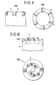
- each cutter When using the composite compact as a cutter for a drill bit, each cutter can strongly be fixed in a recess provided in the crown of the drill bit as shown in Fig. 6 by press-fitting or shrink fitting the substrate part (5 in Fig. 3 (a) and 6 in Fig. 3 (b)) of the cutter therein.
- the substrate part has a larger volume, in particular, this fixing can be carried out without degrading the diamond or BN compact even by the ordinary brazing method.
- bit body 9 of steel itself can be used as the substrate and the composite compact 8 without substrate can directly be bonded thereto, as shown in Fig. 5.
- the hard materials in the hard sintered alloys of the base and substrate are diffused, dispersed and precipitated in a high strength metal or alloy as the filler metal, whereby the strength and wear resistance of the filler metal are further increased and the interfacial strength of the hard sintered alloy and filler metal is more increased.
- the substrate used herein (5 and 6 in Fig. 3) is of the same hard sintered alloy as that of the base (2 in Fig. 3) and the filler metal used herein is an iron group metal or its alloy.
- Co or Ni is preferably used as the filler metal because Co or Ni is also preferably used as the binder metal in the hard sintered alloy and does not result in metallurgical defects such as lowering the bond strength during melting and bonding.
- the filler metal hardly reacts with, for example, a carbide such as WC or (Mo, W) C in the hard sintered alloy to form and precipitate a brittle composite carbide phase, and there is dispersed and precipitated a carbide having the same composition as WC or (Mo, W) C in the hard sintered alloy in the filler metal when solidified, thus resulting in a much higher bond strength.
- the content of the hard material, such as carbides, dispersed and precipitated in the interlayer is preferably 0.1 to 60 vol. %, since if the content is less than 0.1 %, it is not desirable to increase the strength of the filler metal, while if more than 60 %, the carbide tends to decompose to form pores in the filler metal and to lower the strength thereof.
- the thickness of the filler metal is preferably 1 mm or less, since if the thickness exceeds 1 mm, the wear resistance of the filler metal is lower than that of the base or substrate.
- a filler metal for bonding the base and substrate there is used another hard sintered alloy having a larger content of an iron group metal than the hard sintered alloys of the base and substrate.
- the invention also covers a process wherein the base, substrate and filler are of hard sintered alloys containing WC or (Mo, W) C optionally with at least one carbide of Ti, Zr, Hf, Cr, V, Nb, and Ta, as a hard phase, and 3 to 80 % by weight of an iron group metal, as a binder metal.
- the base and substrate are also bonded under such a condition that the diamond or BN compact is not degraded and to this end, a high energy narrow beam such as electron beam or laser beam is used as a heating source for localized heating to only the joint part. It is not impossible to heat and melt the hard sintered alloy itself to be joined, but by this procedure, it is difficult to obtain a bond with a sufficiently high strength.
- a butt welding test by electron beam is carried out using WC-12 % Co alloy and the bond interface is observed, a number of pores are found and there is an abnormal phase due to decarburization in the structure. This is considered to be due to decomposition of a part of WC in the alloy and its combination with 0 2 in the atmosphere to yield CO gas.
- a hard sintered alloy used for the base and substrate of the diamond or BN compact should have a sufficient hardness and wear resistance as well as a sufficient rigidity to reinforce the compact layer, in particular, when the composite compact or blank is used as a cutter of a drill bit. Therefore, it is required to select an alloy with a binder metal in a suitable range and generally a binder metal quantity of 3 to 20 % by weight is suitable for this purpose. As described above, however, an alloy with a further larger content of binder metal is suitable for bonding.
- this filler metal is a hard sintered alloy preferably comprising 20 to 80 % by weight of a binder metal and a carbide the same as or similar to the base or substrate as hard grains.
- the quantity of a binder metal is less than 20 % by weight, a weld defect tends to occur, while if more than 80 % by weight, increase of the strength due to the hard carbide grains cannot be held, but there is only obtained a strength similar to that of ordinary filler metals.
- the hard carbide. WC or (Mo, W) C is preferable from the standpoint of strength and the binder metal Ni is superior to Co and Fe because of the above described reason.
- the thickness of the filler should be 2 mm or less, preferably 0.05 to 1 mm. If less than the lower range, the thickness may be smaller than the beam diameter of the electron beam or laser beam so that the base and substrate are partially fused. Since the filler material according to this embodiment is similar to the materials to be bonded and has a similar coefficient of thermal expansion thereto, there is little strain due to welding.
- the base, substrate and joint layer are of hard sintered alloys containing WC or (Mo, W) C optionally with at least one carbide of Ti, Zr, Hf, Cr, V, Nb or Ta, as a hard phase, and 3 to 80 % by weight of an iron group metal, as a binder metal.
- the hard sintered alloys of the base and substrate contain an iron group metal in a proportion of 3 to 20 % by weight and the hard sintered alloy of the joint layer contains 20 to 80 % by weight of Ni, O to 60 % by weight of Co and O to 60 % by weight of Fe.
- one of the base and substrate has a projection and the other has a complementary slot.
- the base and substrate are contacted and bonded through a high strength metal or alloy with a thickness of at most 2 mm in such a manner that the projection is fixed into the slot.
- the high strength metal or alloy has a melting point of at least the liquidus point of the hard sintered alloy, as.set forth above.
- Fig. 7 1, 2 and 3 of Fig. 7 are the same as those of Fig. 2.
- the base and substrate are worked as shown in Fig. 7.
- Sheet 4 of a high strength metal or alloy having a ring shape and a thickness of 2 mm or less is sandwiched between the base and the substrate and melted and bonded instantaneously by the use of narrow high energy beam 6 such as an electron beam or laser beam, as shown in Fig. 7.
- the filler metal or alloy to be inserted in between the base and substrate should be chosen from materials having a much higher bond strength after being melted and solidified than the ordinary brazing materials, in particular, from iron group metals such as Fe, Ni and Co and their alloys containing iron group metals as a predominant component.
- iron group metals such as Fe, Ni and Co
- the base and substrate have respectively a projection and a slot to be fitted together and this combination gives a very high shear strength.
- the joint part is exposed to a high shearing stress to cause separation thereof when the joint part is brazed, but the compsite compact tool according to this embodiment is free from this problem because of its high shearing strength and high reliability.
- the materials of the base and substrate used in this embodiment are generally the same as those used in the above described embodiments.
- the base can directly be bonded ,I to the substrate without using a joint layer, i.e. filler metal or alloy.
- composite compact 1 is bonded to substrate 5 or 6 of steel by melting contacted or abutting surface 4 instantaneously using a narrow beam 7 of high energy, such as an electron or laser beam.
- a narrow beam 7 of high energy such as an electron or laser beam.
- direct bonding is possible without provision of an interlayer of brazing material on the joint surface and is completed by heating only the joint part immediately before diamond or BN compact reaches a temperature at which it is degraded.
- Substrate 5 or 6 used in this embodiment is generally of steel, preferably of steel subjected to a heat treatment, such as high speed steel or tool steel.
- the former contains a large amount of heat resisting compound such as carbide and thus melting thereof is insufficient even if the electron beam is applied to only the abutting surface of the former side, while irradiation of only the abutting surface of the latter side with electron beam results in a larger melting depth and markedly lower bond strength.
- a high energy beam such as an electron beam is applied in such a manner that both the abutting surfaces of the hard sintered alloy and the steel are irradiated, the base side of the hard sintered alloy is heated and the substrate side of steel is provided with a melt zone in a narrow range of the joint end, whereby the base and substrate can directly be bonded with a higher bond strength and without degrading the structure of the hard sintered alloy.
- a high energy beam such as an electron beam is applied in such a manner that both the abutting surfaces of the hard sintered alloy and the steel are irradiated, the base side of the hard sintered alloy is heated and the substrate side of steel is provided with a melt zone in a narrow range of the joint end, whereby the base and substrate can directly be bonded with a higher bond strength and without degrading the structure of the hard sintered alloy.
- the melted layer is formed in the steel part and the hard sintered alloy part is not melted, so that no brittle layer is formed through reaction of the hard sintered
- the edge part in particular, the exterior part of the cemented carbide blade is worn to blunt the edge and to increase the drilling resistance and the temperature of the edge rises to lower the strength of the edge, leading to breakage.
- it is found necessary to increase the wear resistance of the cemented carbide blade in order to lengthen the life thereof.
- the above described diamond or BN compact has excellent features as a tool material, but since an ultra-high pressure apparatus is.required for the production, the compact is restricted considerably as to its shape or size and is expensive. Accordingly, this drag bit is made for trial considering that use of a diamond or BN compact on only an area of cemented carbide blade to be much worn as shown in Fig. 9 results in a lengthened life of the bit and a decreased production cost.
- bonding of the composite diamond or BN compact should also be carried out so that there can be obtained a bond strength which is higher and is not so lowered at high temperatures.
- the inventors have made various studies as to this bonding and consequently, have found that a high strength bond can be obtained without degrading the diamond compact by arranging the composite compact and cemented carbide blade through a high strength metal or alloy having a thickness of at most 1 mm and a melting point of at least the liquidus point of the cemented carbide, applying a high energy beam such as electron beam or laser beam to the metal or alloy and thereby melting and bonding only the metal or alloy.
- the filler metal or alloy there are preferably used iron group metals such as Fe, Ni and Co and alloys thereof containing iron group metals as a predominant component.
- the cemented carbide blades 1 used in this embodiment are of a cemented carbide the same as or similar to that of base 13 (2 of Fig. 2).
- Co or Ni is preferably used as the filler metal because Co or Ni may also be used as the binder metal in the cemented carbide and does not result in metallurgical defects such as lowering the bond strength during melting and bonding.
- Ni or Ni alloys as the filler metal (21 of Fig. 9 and 22 of Fig.
- the filler metal hardly reacts with, for example, a carbide such as WC or (Mo, W) C in the cemented carbide to form and precipitate a brittle composite carbide phase and there is dispersed and precipitated a carbide having the same composition as WC or (Mo, W) C in the cemented carbide in the filler metal after solidification, thus resulting in a much higher bond strength.
- a carbide such as WC or (Mo, W) C in the cemented carbide to form and precipitate a brittle composite carbide phase and there is dispersed and precipitated a carbide having the same composition as WC or (Mo, W) C in the cemented carbide in the filler metal after solidification, thus resulting in a much higher bond strength.
- the present invention has mainly been illustrated as to the preferred embodiments when applied to drill bits, but is of course useful for other uses, for example, cutting tools, drilling tools, dressers of grinding wheel and wear resisting tools, in particular, in case where the joint area of a compact cutter and tool substrate is relatively small and the bond strength is lacking by the ordinary brazing method.
- a composite compact as a cutter is bonded to a tool body by electron beam.
- the compact preferably comprises a diamond compact containing at least 70 % by volume of diamond or a high pressure form boron nitride compact containing at least 55 % by volume of high pressure form boron nitride and a base.
- electron beam welding is carried out by emitting an electron beam in vacuum, irradiating a part to be welded with the beam and heating and melting it by the energy of the electron beam. Since the diameter of the beam can be focussed to O.5 mm or less, only a part to be welded is spot- like heated. Moreover, the welding can be completed in a short time because of the very high energy density of the electron beam, and a bond strength substantially corresponding to the strength of the materials to be welded can be obtained by melting and bonding these materials themselves when they are welded each other directly or through a filler inserted between them. That is to say, a high strength bond can be obtained by electron beam welding without raising substantially the temperature of the composite compact. In this case, the same materials as set forth above can be used as the filler.
- the above described composite micro tool is, for example, an end mill as shown in Fig. ll, in which hard compact 1 is bonded by electron beam to the end of tool body 3 of steel through interface 11 of base 2 and and tool body 3. Diameter d of tool body 3 is 2 mm and no filler metal is used.
- a composite micro diameter drill comprising a diamond compact containing at least 70 % by volume of diamond and a base fixed as a cutter, in which the diamond compact blank is bonded to the drill body by electron beam welding.
- the diameter of the drill is preferably up to 3 mm, more preferably 1 mm.
- Diamond compact 1 with a diameter of 10 mm and a thickness of O.5 mm as shown in Fig. 2 was prepared by sintering about 90 % by volume of diamond grains with Co as a binder under an ultra-high pressure and high temperature.
- This composite diamond compact was bonded to substrate 5 with a diameter of 10 mm and a length of 10mm, made of WC- 12 % Co, using sheet 4 with a diameter of 10 mm and a thickness of 0.3 mm, made of Fe- 42 % Ni, as a filler metal.
- these components were combined as shown in Fig. 3 (a), charged in a vacuum chamber and subjected to electron beam welding 7 under an accelerating voltage of 100 KV, beam current of 20 mA, beam diameter of about 0.3 mm and welding speed of 0.5 m/min (welding time: about 1 sec per one sample), thus fusing the filler metal.
- Example 2 Six composite diamond compacts 8 having the same structure as used in Example 1 were bonded to bit body 9 made of SCM steel directly by electron beam welding. This bonding was carried out in an analogous manner to Example 1 using a core bit body with a diameter of 60 mm shown in Fig. 5 (a) and (b) as a substrate and a sheet of Ni with a thickness of 0.5 mm as a filler metal.
- Diamond compact 1 with a diameter of lO mm and a thickness of 0.5 mm as shown in Fig. 2 was prepared by sintering about 90 % by volume of diamond grains with Co as a binder under an ultra-high pressure and high temperature.
- the resulting composite diamond compact was bonded to substrate 5 of WC- 12 % Co, having a diameter of 10 mm and a length of 10 mm, using sheet 4 of Ni, having a diameter of 11 mm and a thickness of 0.5 mm, as a filler metal. After degreasing, washing and demagnetizing, these components were combined as shown in Fig. 3 (a), charged in a vacuum chamber and subjected to electron beam welding under an accelerating voltage of 150 KV, beam current of 6 mA and beam diameter of 0.3 mm for 2 seconds, thus fusing the Ni filler metal. After welding, the composite compact sample was cut and subjected to observation by an X-ray microanalyzer to obtain results as shown in Fig. 12 (a), (b), (c) and (d).
- Fig. 12 (a), (b), (c) and (d) are respectively a back scattered electron image, Ni X-ray image, Co X-ray image and W X-ray image.
- W and Co the components of WC-Co alloys, were diffused in the Ni filler metal and WC, the hard material, was precipitated in a proportion of 15 % by volume. Ni was also diffused in the cemented carbides.
- the shearing strength of the joint part was measured.
- another sample was prepared by brazing the same composite compact and substrate with a silver braze corresponding to JIS BAg-1 and similarly subjected to measurement of the shearing strength. Consequently, the sample of the present invention showed 80 Kg/mm 2 at normal temperature and 70 Kg/mm even at 350 °C, while the comparative sample showed respectively 20 Kg/mm2 and 2 12 Kg/mm 2 .
- Composite diamond compact having the same structure as used in Example 3, as shown in Fig. 3 (a), was press-fit in a bit body made of SCM steel to prepare a core bit having a diameter of 60 mm and three cutters.
- a composite diamond compact comprising a commercially sold diamond compact for a bit, bonded to a cemented carbide by brazing, was similarly adapted to a bit body of SCM steel to prepare a core bit.
- the bit of the present invention was free from missing of the compact cutters and capable of further use, while the comparison bit met with missing of the two diamond compacts from the brazed part.
- a diamond compact having a thickness of 0.5 mm and comprising 80 % by volume of diamond grains sintered with binders of (Mo, W) C, Ni and Co under an ultra-high pressure and high temperature was directly bonded to a base of (Mo, W) C- 15 % Co alloy with a diameter of 14 mm to prepare a composite diamond compact blank with a thickness of 3.5 mm.
- the resulting composite diamond compact was bonded to a substrate of (Mo, W) C- 20 % Ni- 5 % Co alloy, having a diameter of 14 mm and a length of 5 mm.
- the diamond compact blank and substrate were bonded through a sheet of Ni, Co or Fe having a diameter of 15 mm and a thickness of 0.6 mm as a filler metal by applying electron beam under an accelerating voltage of 150 KV, beam current of 10 mA and beam diameter of 0.3 mm for 5 seconds.
- the shearing strengths of the resulting samples measured at normal temperature were 85 Kg/mm 2 in the case of using Ni as the filler metal, 79 Kg/mm2 in the case of using Co and 70 Kg/mm2 in the case of using Fe.
- Diamond compact 1 with a diameter of 10 mm and a thickness of 0.5 mm as shown in Fig. 2 was prepared by sintering about 90 % by volume of diamond grains with Co as a binder under an ultra-high pressure and high temperature.
- the resulting composite diamond compact was bonded to substrate 5 of WC- 12 % Co alloy, having a diameter of 10 mm and a length of 10 mm, using sheet 4 of WC- 30 % Ni alloy, having a diameter of 10 mm and a thickness of 0.3 mm, as a filler metal.
- these components were combined as shown in Fig. 3 (a), charged in a vacuum chamber and subjected to electron .beam welding under an accelerating voltage of 150 KV, beam current of 15 mA, beam diameter of about 0.3 mm and welding speed of 0.5 m/min (welding time: about 1 second per one sample), thus fusing the filler metal.
- the resulting both samples were subjected to measurement of the shearing strength at normal temperature and at 350 °C, thus obtaining results of 80 Kg/mm 2 at normal temperature and 75 Kg/mm 2 even at 350 C for the sample of the present invention and on the other hand, 20 Kg/mm 2 and 12 Kg/mm 2 for the comparative sample.
- Example 6 The procedure of Example 6 was repeated except using, in place of the WC- 30 % Ni alloy as the filler, a compact of mixed powders of WC and 30 % by weight of Ni, subjected to intermediate sintering at 700 °C for 30 minutes, thus obtaining similar results to those of Example 6.
- a diamond compact as shown in Fig. 2 was prepared by sintering under an ultra.-high pressure and high temperature in an analogous manner to Example 6 and bonded to a substrate of WC- 20 % Co alloy, having a shape as shown in Fig. 3 (b), 6, through a sheet of (Mo 0.5 W 0.5 ) C- 30 % Ni- 30 % Co alloy, having a thickness of 0.5 mm by electron beam welding under the similar welding conditions to those of Example 6.
- Eight.samples of composite diamond compact component 8 were prepared and press-fit in bit body 9 of steel to thus obtain a bit having a bit diameter of 76.2 mm, as shown in Fig. 6 (a) as front view and (b) as plan view.
- another bit was prepared using a composite diamond compact brazed with a silver braze, as shown in Fig. 3 (b).
- the bit using the cutter of the present invention was capable of drilling by at least 50 m without any problem, while the other comparative bit was broken in drilling only by lOm. In the latter sample, the diamond compact was missed from the brazed part.
- a composite diamond compact was prepared by bonding a diamond compact to a base of WC- 12 % Co alloy similar to Example 6 and bonded to a substrate having a diameter of 10 mm and a length of 10 mm through a filler material having a thickness of O.5 mm by electron beam welding, the materials of the substrate and filler being varied as shown in Table 1.
- the shearing strength of the welded joint part of the each sample was measured to obtain results tabulated below:
- Diamond compact 1 with a diameter of 10 mm and a thickness of 0.5 mm as shown in Fig. 2 was prepared by sintering about 90 % by volume of diamond grains with Co as a binder under an ultra-high pressure and high temperature.
- Base 2 of WC- 6 % Co alloy having a thickness of 3 mm was simultaneously bonded to diamond compact 1 when it was sintered through interlayer 3 with a thickness of 40 pm, consisting of a compact of 60 % by volume of CBN and TiN- 10 wt % Al. Then, the cemented carbide base was worked so as to have a projection of 3 mm in outer diameter and 1 mm in height, as shown in Fig. 7 (a).
- an Ni plate having an outer diameter of 11 mm, inner diameter of 3.05 mm and thickness of 0.3 mm and a cemented carbide substrate having an inner diameter of 3.05 mm and depth of 1 mm were prepared. These components were combined as shown in Fig. 7 (a), charged in a vacuum chamber and subjected to electron beam welding with revolving under an accelerating voltage of 150 KV, beam current of 5 mA and beam diameter of 0.3 mm for 2 seconds. When the sample after welded was observed, the composite diamond compact and cemented carbide were strongly bonded without cracks.
- comparative sample 1 was prepared by brazing the same compact and substrate with a silver braze corresponding to JIS BAg-1 and comparative sample 2 was prepared by electron beam welding of the flat surfaces of the diamond compact base and cemented carbide substrate using a Ni plate with a thickness of 0.3 mm.
- the sample of the present invention was not broken by 100 Kg/mm 2 at normal temperature and even at 350 °C, while comparative samples 1 and 2 showed respectively 20 Kg/mm 2 and 12 Kg/mm 2 , and 60 Kg/mm 2 and 50 Kg/mm .
- a composite diamond compact having the same structure as used in Example 9 as shown in Fig. 2 and steel substrate were worked as shown in Fig. 7 (b) and bonded by electron beam welding using a sheet of Fe-Ni with a thickness of 0.5 mm as a filler metal. Then, this steel substrate was pressfit into a bit body made of SCM steel to make a core bit having four cutters.
- Diamond compact 1 with a diameter of 10 mm and a thickness of 0.5 mm as shown in Fig. 2 was prepared by sintering about 90 % by volume of diamond grains with Co as a binder under an ultra-high pressure and high temperature.
- the resulting composite diamond compact was bonded to substrate 5 with a diameter of 10 mm and a length of 10 mm, made of hot die steel SKD 11 (HRC 55).
- Fig. 3 (a) After degreasing, washing and demagnetizing, these components were combined as shown in Fig. 3 (a), charged in a vacuum chamber and the butted ends of the base and steel substrate were irradiated with electron beam under an accelerating voltage of 100 KV, beam current of 20 mA, beam diameter of about 0.3 mm and welding rate of 0.5 m/min (welding time: about 1 second per one sample), thus fusing the steel and bonding.
- Example 12 Four composite diamond compacts 8 having the same structure as used.in Example 12, as shown in Fig. 2, were directly bonded to bit body 9 made of SCM steel by electron beam welding. This bonding was carried out in an analogous manner to Example 12 using core bit body 7 with a diameter of 60 mm shown in Fig. 5 (a) and (b) as a substrate.
- Diamond compact 1 with a diameter of 13 mm and a thickness of 0.8 mm as shown in Fig. 2 was prepared by sintering about 90 % by volume of diamond grains with Co as a binder under an ultra-high pressure and high temperature.
- Base 2 of WC- 6 % Co, having a thickness of 2 mm, was simultaneously bonded to diamond compact 1 when it was sintered through interlayer 3 with a thickness of 50 pm, consisting of a compact of 60 % by volume of CBN and TiN- 10 wt % Al.
- the resulting composite diamond compact was divided into three equal parts to give a 120 0 segment and bonded to cemented carbide blade 1 through Ni plate 22 with a thickness of 0.5 mm as a filler metal as shown in'Fig.
- comparative sample 1 i.e. cemented carbide blade bit and comparative sample 2 prepared by brazing the above described composite diamond compact to a cemented carbide blade with a silver braze were also subjected to a drilling test. Consequently, the sample of the present invention could further be used even after drilling 100 m, while comparative sample 1 was broken and exhausted by 50 m and comparative sample 2 met with missing of the diamond compact from the brazed part when drilling 30 m.
- Composite diamond compact blank 1 + 2 was bonded to the end of drill body 3 consisting of a cemented carbide through joint surface 11 by electron beam welding, worked in a shape of drill with a diameter of 1 mm by grinding and then subjected to a drilling test of a printed circuit board, as shown in Fig. 4.
- Composite compact consisting of 60 % by volume of CBN and the balance of a binder phase of 85 % by weight of TiN and 15 % by weight of Al, having a thickness of 0.5 mm, was bonded to a base of WC- 10 % Co alloy, having a thickness of 0.5 mm during sintering under an ultra-high pressure and high temperature to prepare a composite compact.
- the resulting composite compact was then bonded to a cutter holder of WC- 10 % Co Alloy, having a diameter of 3 mm through an Ni foil having a thickness of 0.2 mm as a filler metal by electron beam welding under an accelerating voltage of 60 KV, beam current of 10 mA and vacuum of 10 2 Torr for 2 seconds, thus obtaining a boring cutter.
- the boring cutter of the present invention was capable of being repeatedly used by repolishing even after making 500 holes, while the comparison cutter met with missing of the CBN compact from the brazed part when making 50 holes.
- Composite compact consisting of 90 % by volume of CBN and the balance of a binder phase of Co and a small amount of Al, having a width of 2 mm and a length of 2 mm, was bonded to a base of WC- 10 % Co alloy during sintering under an ultra-high pressure and high temperature to prepare a composite compact.
- the resulting composite compact was then bonded to a cutter holder of WC- lO % Co alloy, having a diameter of 4 mm through a Ni thin sheet having a thickness of 0.2 mm as a filler metal by means of a C0 2 laser welding apparatus, thus obtaining an end mill, as shown in Fig. 11.
Applications Claiming Priority (16)
| Application Number | Priority Date | Filing Date | Title |
|---|---|---|---|
| JP180054/81 | 1981-11-09 | ||
| JP18005381A JPS5884187A (ja) | 1981-11-09 | 1981-11-09 | 複合焼結体工具およびその製造方法 |
| JP180053/81 | 1981-11-09 | ||
| JP18005481A JPS5884188A (ja) | 1981-11-09 | 1981-11-09 | 複合焼結体工具およびその製造方法 |
| JP57109171A JPS591104A (ja) | 1982-06-24 | 1982-06-24 | 複合焼結体工具およびその製造方法 |
| JP109171/82 | 1982-06-24 | ||
| JP12765182U JPS5932310U (ja) | 1982-08-23 | 1982-08-23 | 複合微少径ドリル |
| JP127651/82U | 1982-08-23 | ||
| JP127650/82U | 1982-08-23 | ||
| JP12765082U JPS5932302U (ja) | 1982-08-23 | 1982-08-23 | 微少複合工具 |
| JP147370/82 | 1982-08-24 | ||
| JP14737082A JPS5939778A (ja) | 1982-08-24 | 1982-08-24 | 複合焼結体工具およびその製造方法 |
| JP149649/82 | 1982-08-27 | ||
| JP57149649A JPS5938491A (ja) | 1982-08-27 | 1982-08-27 | 複合焼結体工具およびその製造法 |
| JP15211282A JPS5941594A (ja) | 1982-08-31 | 1982-08-31 | ドリルビツト |
| JP152112/82 | 1982-08-31 |
Publications (2)
| Publication Number | Publication Date |
|---|---|
| EP0079243A1 true EP0079243A1 (de) | 1983-05-18 |
| EP0079243B1 EP0079243B1 (de) | 1986-12-30 |
Family
ID=27573001
Family Applications (1)
| Application Number | Title | Priority Date | Filing Date |
|---|---|---|---|
| EP82305971A Expired EP0079243B1 (de) | 1981-11-09 | 1982-11-09 | Kompaktverbundkörper der einen Presskörper aus Diamant oder Bornitrid enthält |
Country Status (4)
| Country | Link |
|---|---|
| US (1) | US4686080A (de) |
| EP (1) | EP0079243B1 (de) |
| CA (1) | CA1216158A (de) |
| DE (1) | DE3274815D1 (de) |
Cited By (15)
| Publication number | Priority date | Publication date | Assignee | Title |
|---|---|---|---|---|
| EP0090657A2 (de) * | 1982-03-31 | 1983-10-05 | De Beers Industrial Diamond Division (Proprietary) Limited | Verfahren zur Herstellung von Schleifkörpern |
| EP0132652A2 (de) * | 1983-07-21 | 1985-02-13 | Precorp Inc. | Verfahren zur Herstellung eines Bohrers für Leiterplatten |
| EP0149530A2 (de) * | 1984-01-16 | 1985-07-24 | CDP, Ltd. | Selbstschärfender Fräsmeissel |
| EP0155026A2 (de) * | 1984-02-29 | 1985-09-18 | Shell Internationale Researchmaatschappij B.V. | Drehbohrmeissel mit Schneidelementen, die mit einer dünnen Schleifstirnschicht ausgerüstet sind |
| EP0163914A1 (de) * | 1984-05-08 | 1985-12-11 | Osaka Diamond Industrial Co. | Schweissmethode für Schneidsegmente |
| EP0193361A1 (de) * | 1985-02-28 | 1986-09-03 | Reed Tool Company Limited | Drehbohrmeissel und Verfahren zur Herstellung solcher Meissel |
| EP0206652A2 (de) * | 1985-06-13 | 1986-12-30 | De Beers Industrial Diamond Division (Proprietary) Limited | Verfahren zum Herstellen eines Rohlings eines Bohrers |
| EP0237359A2 (de) * | 1986-03-13 | 1987-09-16 | Smith International, Inc. | Fräsdrehbohrmeissel |
| EP0238938A1 (de) * | 1986-03-24 | 1987-09-30 | General Electric Company | Stift mit Tasche für Schneidwerkzeug mit polykristallinen Diamanten |
| US4762445A (en) * | 1985-06-03 | 1988-08-09 | Precorp, Inc. | Composite sintered twist drill |
| EP0315221A2 (de) * | 1985-02-28 | 1989-05-10 | Reed Tool Company Limited | Drehbohrmeissel und Verfahren zur Herstellung solcher Meissel |
| EP0422435A2 (de) * | 1989-10-12 | 1991-04-17 | General Electric Company | Gepresster Diamant zum Bohren und Bearbeiten von Gestein |
| CN104759724A (zh) * | 2015-05-07 | 2015-07-08 | 东北石油大学 | 使用激光加热连接超长硬质合金的焊接方法 |
| CN109551353A (zh) * | 2018-12-12 | 2019-04-02 | 蓝思科技(长沙)有限公司 | 一种抛光磨棒及其抛光工艺 |
| US10512974B1 (en) * | 2016-12-07 | 2019-12-24 | Quantum Valley Investment Fund LP | Diamond machining tool |
Families Citing this family (100)
| Publication number | Priority date | Publication date | Assignee | Title |
|---|---|---|---|---|
| CA1248519A (en) * | 1984-04-03 | 1989-01-10 | Tetsuo Nakai | Composite tool and a process for the production of the same |
| EP0168953B2 (de) * | 1984-06-12 | 1998-07-01 | Sumitomo Electric Industries Limited | Stab aus Verbundmaterialien und Verfahren zu seiner Herstellung |
| GB8418481D0 (en) * | 1984-07-19 | 1984-08-22 | Nl Petroleum Prod | Rotary drill bits |
| KR920010861B1 (ko) * | 1984-11-01 | 1992-12-19 | 스미또모덴끼고오교 가부시끼가이샤 | 샌드위치형 구조의 고경도 소결체 복합재료 |
| US4781256A (en) * | 1984-12-14 | 1988-11-01 | Nl Petroleum Products Limited | Cutting structures for rotary drill bits |
| US4802895A (en) * | 1986-07-14 | 1989-02-07 | Burnand Richard P | Composite diamond abrasive compact |
| US4871377A (en) * | 1986-07-30 | 1989-10-03 | Frushour Robert H | Composite abrasive compact having high thermal stability and transverse rupture strength |
| IE60131B1 (en) * | 1986-09-24 | 1994-06-01 | De Beers Ind Diamond | Thermally stable diamond abrasive compact body |
| JPS63156082A (ja) * | 1986-12-19 | 1988-06-29 | 日本油脂株式会社 | 高硬度焼結体 |
| ATE86537T1 (de) * | 1986-12-23 | 1993-03-15 | De Beers Ind Diamond | Werkzeugeinsatz. |
| JPS63169356A (ja) * | 1987-01-05 | 1988-07-13 | Toshiba Tungaloy Co Ltd | 表面調質焼結合金及びその製造方法 |
| DE3706340A1 (de) * | 1987-02-27 | 1988-09-08 | Winter & Sohn Ernst | Verfahren zum auftragen einer verschleissschutzschicht und danach hergestelltes erzeugnis |
| US4766040A (en) * | 1987-06-26 | 1988-08-23 | Sandvik Aktiebolag | Temperature resistant abrasive polycrystalline diamond bodies |
| US4764434A (en) * | 1987-06-26 | 1988-08-16 | Sandvik Aktiebolag | Diamond tools for rock drilling and machining |
| AT387988B (de) * | 1987-08-31 | 1989-04-10 | Plansee Tizit Gmbh | Verfahren zur herstellung mehrlagig beschichteter hartmetallteile |
| IE61697B1 (en) * | 1987-12-22 | 1994-11-16 | De Beers Ind Diamond | Abrasive product |
| US5032147A (en) * | 1988-02-08 | 1991-07-16 | Frushour Robert H | High strength composite component and method of fabrication |
| US5111895A (en) * | 1988-03-11 | 1992-05-12 | Griffin Nigel D | Cutting elements for rotary drill bits |
| GB2234542B (en) * | 1989-08-04 | 1993-03-31 | Reed Tool Co | Improvements in or relating to cutting elements for rotary drill bits |
| US5066173A (en) * | 1990-01-31 | 1991-11-19 | Gte Valenite Corporation | Aluminum piston wrist pin boring tool |
| US5033560A (en) * | 1990-07-24 | 1991-07-23 | Dresser Industries, Inc. | Drill bit with decreasing diameter cutters |
| US5492770A (en) * | 1990-08-03 | 1996-02-20 | Fujitsu Limited | Method and apparatus for vapor deposition of diamond film |
| DE69205075T2 (de) * | 1991-06-25 | 1996-03-21 | Sumitomo Electric Industries | Hartgesinterter Presskörper für Werkzeuge. |
| JPH06198504A (ja) * | 1993-01-07 | 1994-07-19 | Sumitomo Electric Ind Ltd | 高硬度焼結体切削工具 |
| SE503038C2 (sv) * | 1993-07-09 | 1996-03-11 | Sandvik Ab | Diamantbelagt skärande verktyg av hårdmetall eller keramik |
| US6264882B1 (en) * | 1994-05-20 | 2001-07-24 | The Regents Of The University Of California | Process for fabricating composite material having high thermal conductivity |
| GB2295837B (en) * | 1994-12-10 | 1998-09-02 | Camco Drilling Group Ltd | Improvements in or relating to elements faced with superhard material |
| US5786559A (en) * | 1995-10-17 | 1998-07-28 | Meyer Tool, Inc. | Weld-braze process |
| JP3633217B2 (ja) * | 1996-09-25 | 2005-03-30 | 松下電工株式会社 | 刃物及びその製造方法 |
| US5979579A (en) * | 1997-07-11 | 1999-11-09 | U.S. Synthetic Corporation | Polycrystalline diamond cutter with enhanced durability |
| DE19744214A1 (de) * | 1997-10-07 | 1999-04-08 | Dialux Diamantwerkzeuge Gmbh & | Schneidwerkzeug, sowie Verfahren zur Beschichtung von Schneidwerkzeugen |
| US6241036B1 (en) | 1998-09-16 | 2001-06-05 | Baker Hughes Incorporated | Reinforced abrasive-impregnated cutting elements, drill bits including same |
| US6220375B1 (en) * | 1999-01-13 | 2001-04-24 | Baker Hughes Incorporated | Polycrystalline diamond cutters having modified residual stresses |
| SE515294C2 (sv) * | 1999-11-25 | 2001-07-09 | Sandvik Ab | Bergborrkrona och stift för slående borrning samt metod att tillverka en bergborrkrona för slående borrning |
| US6571493B2 (en) * | 1999-12-27 | 2003-06-03 | Komatsu Ltd. | Cutting edge |
| KR100440870B1 (ko) * | 2001-02-19 | 2004-07-19 | 이화다이아몬드공업 주식회사 | 언더컷 방지용 팁을 이용한 다이아몬드 소우 블레이드 |
| US6800519B2 (en) * | 2001-09-27 | 2004-10-05 | Kabushiki Kaisha Toshiba | Semiconductor device and method of manufacturing the same |
| DE10233530A1 (de) * | 2002-07-23 | 2004-02-12 | Komet Präzisionswerkzeuge Robert Breuning Gmbh | Maschinenwerkzeug mit einem Werkzeugschaft und einem Schneidkopf |
| US7517588B2 (en) * | 2003-10-08 | 2009-04-14 | Frushour Robert H | High abrasion resistant polycrystalline diamond composite |
| US7595110B2 (en) * | 2003-10-08 | 2009-09-29 | Frushour Robert H | Polycrystalline diamond composite |
| SE525996C2 (sv) * | 2003-10-16 | 2005-06-07 | Sandvik Ab | Förfarande för framställning av skärverktyg där två delar är sammanfogade medelst lasersvetsning |
| US7395882B2 (en) * | 2004-02-19 | 2008-07-08 | Baker Hughes Incorporated | Casing and liner drilling bits |
| US7954570B2 (en) * | 2004-02-19 | 2011-06-07 | Baker Hughes Incorporated | Cutting elements configured for casing component drillout and earth boring drill bits including same |
| US9428822B2 (en) | 2004-04-28 | 2016-08-30 | Baker Hughes Incorporated | Earth-boring tools and components thereof including material having hard phase in a metallic binder, and metallic binder compositions for use in forming such tools and components |
| US20050211475A1 (en) * | 2004-04-28 | 2005-09-29 | Mirchandani Prakash K | Earth-boring bits |
| US7513320B2 (en) | 2004-12-16 | 2009-04-07 | Tdy Industries, Inc. | Cemented carbide inserts for earth-boring bits |
| US8637127B2 (en) | 2005-06-27 | 2014-01-28 | Kennametal Inc. | Composite article with coolant channels and tool fabrication method |
| US7687156B2 (en) | 2005-08-18 | 2010-03-30 | Tdy Industries, Inc. | Composite cutting inserts and methods of making the same |
| US7597159B2 (en) | 2005-09-09 | 2009-10-06 | Baker Hughes Incorporated | Drill bits and drilling tools including abrasive wear-resistant materials |
| US7997359B2 (en) * | 2005-09-09 | 2011-08-16 | Baker Hughes Incorporated | Abrasive wear-resistant hardfacing materials, drill bits and drilling tools including abrasive wear-resistant hardfacing materials |
| US7776256B2 (en) * | 2005-11-10 | 2010-08-17 | Baker Huges Incorporated | Earth-boring rotary drill bits and methods of manufacturing earth-boring rotary drill bits having particle-matrix composite bit bodies |
| US8002052B2 (en) | 2005-09-09 | 2011-08-23 | Baker Hughes Incorporated | Particle-matrix composite drill bits with hardfacing |
| US7703555B2 (en) * | 2005-09-09 | 2010-04-27 | Baker Hughes Incorporated | Drilling tools having hardfacing with nickel-based matrix materials and hard particles |
| US7802495B2 (en) * | 2005-11-10 | 2010-09-28 | Baker Hughes Incorporated | Methods of forming earth-boring rotary drill bits |
| US8770324B2 (en) | 2008-06-10 | 2014-07-08 | Baker Hughes Incorporated | Earth-boring tools including sinterbonded components and partially formed tools configured to be sinterbonded |
| US7807099B2 (en) * | 2005-11-10 | 2010-10-05 | Baker Hughes Incorporated | Method for forming earth-boring tools comprising silicon carbide composite materials |
| US7913779B2 (en) * | 2005-11-10 | 2011-03-29 | Baker Hughes Incorporated | Earth-boring rotary drill bits including bit bodies having boron carbide particles in aluminum or aluminum-based alloy matrix materials, and methods for forming such bits |
| US7784567B2 (en) * | 2005-11-10 | 2010-08-31 | Baker Hughes Incorporated | Earth-boring rotary drill bits including bit bodies comprising reinforced titanium or titanium-based alloy matrix materials, and methods for forming such bits |
| CA2648181C (en) | 2006-04-27 | 2014-02-18 | Tdy Industries, Inc. | Modular fixed cutter earth-boring bits, modular fixed cutter earth-boring bit bodies, and related methods |
| WO2008027484A1 (en) * | 2006-08-30 | 2008-03-06 | Baker Hughes Incorporated | Methods for applying wear-resistant material to exterior surfaces of earth-boring tools and resulting structures |
| DE102006042752A1 (de) * | 2006-09-12 | 2008-03-27 | Shw Casting Technologies Gmbh | Verfahren zur Herstellung eines Rohrkörpers für die Weiterbearbeitung zu einer Walze |
| BRPI0717332A2 (pt) | 2006-10-25 | 2013-10-29 | Tdy Ind Inc | Artigos tendo resistência aperfeiçoada à rachadura térmica |
| US7775287B2 (en) * | 2006-12-12 | 2010-08-17 | Baker Hughes Incorporated | Methods of attaching a shank to a body of an earth-boring drilling tool, and tools formed by such methods |
| US7841259B2 (en) | 2006-12-27 | 2010-11-30 | Baker Hughes Incorporated | Methods of forming bit bodies |
| US8518043B2 (en) * | 2007-02-09 | 2013-08-27 | Christopher G. Sidebotham | Modular spherical hollow reamer assembly for medical applications |
| US7846551B2 (en) | 2007-03-16 | 2010-12-07 | Tdy Industries, Inc. | Composite articles |
| US7857194B2 (en) * | 2007-05-01 | 2010-12-28 | University Of Dayton | Method of joining metals to ceramic matrix composites |
| US7665234B2 (en) * | 2007-09-14 | 2010-02-23 | Kennametal Inc. | Grader blade with tri-grade insert assembly on the leading edge |
| JP5108630B2 (ja) * | 2008-05-27 | 2012-12-26 | 兼房株式会社 | 平板状刃物 |
| US8221517B2 (en) | 2008-06-02 | 2012-07-17 | TDY Industries, LLC | Cemented carbide—metallic alloy composites |
| US8790439B2 (en) | 2008-06-02 | 2014-07-29 | Kennametal Inc. | Composite sintered powder metal articles |
| US7703556B2 (en) | 2008-06-04 | 2010-04-27 | Baker Hughes Incorporated | Methods of attaching a shank to a body of an earth-boring tool including a load-bearing joint and tools formed by such methods |
| US20090308662A1 (en) * | 2008-06-11 | 2009-12-17 | Lyons Nicholas J | Method of selectively adapting material properties across a rock bit cone |
| US8261632B2 (en) | 2008-07-09 | 2012-09-11 | Baker Hughes Incorporated | Methods of forming earth-boring drill bits |
| US8322465B2 (en) | 2008-08-22 | 2012-12-04 | TDY Industries, LLC | Earth-boring bit parts including hybrid cemented carbides and methods of making the same |
| US8025112B2 (en) | 2008-08-22 | 2011-09-27 | Tdy Industries, Inc. | Earth-boring bits and other parts including cemented carbide |
| US8272816B2 (en) | 2009-05-12 | 2012-09-25 | TDY Industries, LLC | Composite cemented carbide rotary cutting tools and rotary cutting tool blanks |
| US8201610B2 (en) | 2009-06-05 | 2012-06-19 | Baker Hughes Incorporated | Methods for manufacturing downhole tools and downhole tool parts |
| US8327955B2 (en) | 2009-06-29 | 2012-12-11 | Baker Hughes Incorporated | Non-parallel face polycrystalline diamond cutter and drilling tools so equipped |
| US8739904B2 (en) * | 2009-08-07 | 2014-06-03 | Baker Hughes Incorporated | Superabrasive cutters with grooves on the cutting face, and drill bits and drilling tools so equipped |
| US8308096B2 (en) | 2009-07-14 | 2012-11-13 | TDY Industries, LLC | Reinforced roll and method of making same |
| US9643236B2 (en) | 2009-11-11 | 2017-05-09 | Landis Solutions Llc | Thread rolling die and method of making same |
| MY160917A (en) * | 2009-12-04 | 2017-03-31 | Nippon Steel Corp | Butt welding joint using high-energy density beam |
| US20130029175A1 (en) * | 2010-04-08 | 2013-01-31 | Tungaloy Corporation | Composite Material |
| SA111320374B1 (ar) | 2010-04-14 | 2015-08-10 | بيكر هوغيس انكوبوريتد | طريقة تشكيل الماسة متعدد البلورات من الماس المستخرج بحجم النانو |
| MX2012013455A (es) | 2010-05-20 | 2013-05-01 | Baker Hughes Inc | Metodos para formar al menos una porcion de herramientas para perforar la tierra y articulos formados por tales metodos. |
| MX2012013454A (es) | 2010-05-20 | 2013-05-01 | Baker Hughes Inc | Metodos para formar al menos una porcion de herramientas para perforar la tierra. |
| WO2011146752A2 (en) | 2010-05-20 | 2011-11-24 | Baker Hughes Incorporated | Methods of forming at least a portion of earth-boring tools, and articles formed by such methods |
| DE102010042814A1 (de) * | 2010-10-22 | 2012-04-26 | Hilti Aktiengesellschaft | Schneidwerkzeug und Herstellungsverfahren |
| US8800848B2 (en) | 2011-08-31 | 2014-08-12 | Kennametal Inc. | Methods of forming wear resistant layers on metallic surfaces |
| US9016406B2 (en) | 2011-09-22 | 2015-04-28 | Kennametal Inc. | Cutting inserts for earth-boring bits |
| US9169696B2 (en) | 2011-12-06 | 2015-10-27 | Baker Hughes Incorporated | Cutting structures, earth-boring tools including such cutting structures, and related methods |
| CN103071817A (zh) * | 2013-02-04 | 2013-05-01 | 侯如升 | 一种用于镗床的三头式扩孔镗刀 |
| US9140072B2 (en) | 2013-02-28 | 2015-09-22 | Baker Hughes Incorporated | Cutting elements including non-planar interfaces, earth-boring tools including such cutting elements, and methods of forming cutting elements |
| US9982490B2 (en) * | 2013-03-01 | 2018-05-29 | Baker Hughes Incorporated | Methods of attaching cutting elements to casing bits and related structures |
| CA2854691C (en) * | 2013-07-03 | 2017-10-31 | Karl H. Moller | Method of making diamond mining core drill bit and reamer |
| USD760843S1 (en) * | 2015-06-08 | 2016-07-05 | Otis Temple, Sr. | Checker type game kit |
| JP6614541B2 (ja) * | 2016-10-07 | 2019-12-04 | 住友電工ハードメタル株式会社 | 回転切削刃用素材及びその製造方法 |
| KR102200515B1 (ko) * | 2017-10-20 | 2021-01-12 | 한국생산기술연구원 | 절삭공구 및 전자빔을 이용한 절삭공구의 브레이징 방법 및 이를 위한 전자빔 장치 |
| CN112677057B (zh) * | 2020-12-29 | 2022-05-03 | 江苏赛扬精工科技有限责任公司 | 一种pcb微钻开槽用金属树脂复合结合剂金刚石砂轮及其制备方法 |
Citations (6)
| Publication number | Priority date | Publication date | Assignee | Title |
|---|---|---|---|---|
| DE947659C (de) * | 1953-05-09 | 1956-08-23 | Karl Hertel | Hartmetallschneidkoerper |
| FR1255677A (fr) * | 1960-04-26 | 1961-03-10 | Objets métalliques durs et leur procédé de fabrication | |
| FR2278436A1 (fr) * | 1974-07-15 | 1976-02-13 | Skf Ind Trading & Dev | Plaquette en carbure metallique soudable |
| EP0003116A1 (de) * | 1978-01-10 | 1979-07-25 | General Electric Company | Kompaktverbundkörper mit hochschmelzendem Hartlötmetall, Verfahren und Vorrichtung zu dessen Herstellung |
| US4168923A (en) * | 1977-10-21 | 1979-09-25 | Smith International, Inc. | Electron beam welding of carbide inserts |
| US4306139A (en) * | 1978-12-28 | 1981-12-15 | Ishikawajima-Harima Jukogyo Kabushiki Kaisha | Method for welding hard metal |
Family Cites Families (6)
| Publication number | Priority date | Publication date | Assignee | Title |
|---|---|---|---|---|
| NL7216832A (de) * | 1972-12-12 | 1974-06-14 | ||
| US4063909A (en) * | 1974-09-18 | 1977-12-20 | Robert Dennis Mitchell | Abrasive compact brazed to a backing |
| US4098362A (en) * | 1976-11-30 | 1978-07-04 | General Electric Company | Rotary drill bit and method for making same |
| US4247305A (en) * | 1979-07-27 | 1981-01-27 | General Electric Company | Abrasive structures and methods of their preparation |
| US4403015A (en) * | 1979-10-06 | 1983-09-06 | Sumitomo Electric Industries, Ltd. | Compound sintered compact for use in a tool and the method for producing the same |
| US4359112A (en) * | 1980-06-19 | 1982-11-16 | Smith International, Inc. | Hybrid diamond insert platform locator and retention method |
-
1982
- 1982-11-08 CA CA000415073A patent/CA1216158A/en not_active Expired
- 1982-11-09 EP EP82305971A patent/EP0079243B1/de not_active Expired
- 1982-11-09 DE DE8282305971T patent/DE3274815D1/de not_active Expired
-
1985
- 1985-12-09 US US06/805,590 patent/US4686080A/en not_active Expired - Fee Related
Patent Citations (6)
| Publication number | Priority date | Publication date | Assignee | Title |
|---|---|---|---|---|
| DE947659C (de) * | 1953-05-09 | 1956-08-23 | Karl Hertel | Hartmetallschneidkoerper |
| FR1255677A (fr) * | 1960-04-26 | 1961-03-10 | Objets métalliques durs et leur procédé de fabrication | |
| FR2278436A1 (fr) * | 1974-07-15 | 1976-02-13 | Skf Ind Trading & Dev | Plaquette en carbure metallique soudable |
| US4168923A (en) * | 1977-10-21 | 1979-09-25 | Smith International, Inc. | Electron beam welding of carbide inserts |
| EP0003116A1 (de) * | 1978-01-10 | 1979-07-25 | General Electric Company | Kompaktverbundkörper mit hochschmelzendem Hartlötmetall, Verfahren und Vorrichtung zu dessen Herstellung |
| US4306139A (en) * | 1978-12-28 | 1981-12-15 | Ishikawajima-Harima Jukogyo Kabushiki Kaisha | Method for welding hard metal |
Cited By (24)
| Publication number | Priority date | Publication date | Assignee | Title |
|---|---|---|---|---|
| EP0090657A2 (de) * | 1982-03-31 | 1983-10-05 | De Beers Industrial Diamond Division (Proprietary) Limited | Verfahren zur Herstellung von Schleifkörpern |
| EP0090657A3 (en) * | 1982-03-31 | 1984-11-14 | De Beers Industrial Diamond Division (Proprietary) Limited | Abrasive bodies |
| EP0132652A2 (de) * | 1983-07-21 | 1985-02-13 | Precorp Inc. | Verfahren zur Herstellung eines Bohrers für Leiterplatten |
| EP0132652B1 (de) * | 1983-07-21 | 1993-05-05 | Precorp Inc. | Verfahren zur Herstellung eines Bohrers für Leiterplatten |
| EP0149530A2 (de) * | 1984-01-16 | 1985-07-24 | CDP, Ltd. | Selbstschärfender Fräsmeissel |
| EP0149530A3 (de) * | 1984-01-16 | 1986-02-05 | CDP, Ltd. | Selbstschärfender Fräsmeissel |
| EP0155026A2 (de) * | 1984-02-29 | 1985-09-18 | Shell Internationale Researchmaatschappij B.V. | Drehbohrmeissel mit Schneidelementen, die mit einer dünnen Schleifstirnschicht ausgerüstet sind |
| EP0155026A3 (en) * | 1984-02-29 | 1986-05-21 | Shell Internationale Research Maatschappij B.V. | Rotary drill bit with cutting elements having a thin abrasive front layer |
| EP0163914A1 (de) * | 1984-05-08 | 1985-12-11 | Osaka Diamond Industrial Co. | Schweissmethode für Schneidsegmente |
| EP0193361A1 (de) * | 1985-02-28 | 1986-09-03 | Reed Tool Company Limited | Drehbohrmeissel und Verfahren zur Herstellung solcher Meissel |
| EP0315221A3 (de) * | 1985-02-28 | 1989-10-25 | Reed Tool Company Limited | Drehbohrmeissel und Verfahren zur Herstellung solcher Meissel |
| EP0315221A2 (de) * | 1985-02-28 | 1989-05-10 | Reed Tool Company Limited | Drehbohrmeissel und Verfahren zur Herstellung solcher Meissel |
| US4762445A (en) * | 1985-06-03 | 1988-08-09 | Precorp, Inc. | Composite sintered twist drill |
| EP0206652B1 (de) * | 1985-06-13 | 1991-10-02 | De Beers Industrial Diamond Division (Proprietary) Limited | Verfahren zum Herstellen eines Rohlings eines Bohrers |
| EP0206652A2 (de) * | 1985-06-13 | 1986-12-30 | De Beers Industrial Diamond Division (Proprietary) Limited | Verfahren zum Herstellen eines Rohlings eines Bohrers |
| EP0237359A3 (de) * | 1986-03-13 | 1988-11-23 | Smith International, Inc. | Fräsdrehbohrmeissel |
| EP0237359A2 (de) * | 1986-03-13 | 1987-09-16 | Smith International, Inc. | Fräsdrehbohrmeissel |
| EP0238938A1 (de) * | 1986-03-24 | 1987-09-30 | General Electric Company | Stift mit Tasche für Schneidwerkzeug mit polykristallinen Diamanten |
| EP0422435A2 (de) * | 1989-10-12 | 1991-04-17 | General Electric Company | Gepresster Diamant zum Bohren und Bearbeiten von Gestein |
| EP0422435A3 (en) * | 1989-10-12 | 1991-06-26 | General Electric Company | Diamond compacts for rock drilling and machining |
| CN104759724A (zh) * | 2015-05-07 | 2015-07-08 | 东北石油大学 | 使用激光加热连接超长硬质合金的焊接方法 |
| US10512974B1 (en) * | 2016-12-07 | 2019-12-24 | Quantum Valley Investment Fund LP | Diamond machining tool |
| CN109551353A (zh) * | 2018-12-12 | 2019-04-02 | 蓝思科技(长沙)有限公司 | 一种抛光磨棒及其抛光工艺 |
| CN109551353B (zh) * | 2018-12-12 | 2020-06-16 | 蓝思科技(长沙)有限公司 | 一种抛光磨棒及其抛光工艺 |
Also Published As
| Publication number | Publication date |
|---|---|
| EP0079243B1 (de) | 1986-12-30 |
| CA1216158A (en) | 1987-01-06 |
| US4686080A (en) | 1987-08-11 |
| DE3274815D1 (en) | 1987-02-05 |
Similar Documents
| Publication | Publication Date | Title |
|---|---|---|
| EP0079243B1 (de) | Kompaktverbundkörper der einen Presskörper aus Diamant oder Bornitrid enthält | |
| EP0157625B1 (de) | Werkzeug aus Verbundwerkstoff | |
| US7435377B2 (en) | Weldable ultrahard materials and associated methods of manufacture | |
| CA1286510C (en) | Stick of composite materials and process for preparation thereof | |
| JP4045014B2 (ja) | 多結晶ダイヤモンド工具 | |
| EP0418078B1 (de) | Mehrschichtiger Schleifkörper | |
| CA2546955C (en) | Thermally stable diamond brazing | |
| US4991467A (en) | Diamond twist drill blank | |
| US20050210755A1 (en) | Doubled-sided and multi-layered PCBN and PCD abrasive articles | |
| CA2667323C (en) | Hard tip and method for producing the same | |
| JP2010264586A (ja) | 切削工具インサートおよびその作成方法 | |
| US5273557A (en) | Twist drills having thermally stable diamond or CBN compacts tips | |
| JP2013519614A (ja) | 超硬要素、その使用方法及びその製造方法 | |
| US4492846A (en) | Process for the production of bonded hard alloys | |
| EP0706850B1 (de) | Lötbare Kobalt enthaltende kubische Bornitrid-Körper | |
| JP2751443B2 (ja) | 硬質多刃ろう付工具及びその製造方法 | |
| JPS6094232A (ja) | 表面被覆焼結硬質合金チツプをろう付けした切削工具の製造法 | |
| JPS58160008A (ja) | 小径超硬ソリツドドリル及びその製造法 | |
| JP2004114190A (ja) | 微細加工用工具 | |
| JPH0525617B2 (de) | ||
| JP2024503988A (ja) | 切削工具 | |
| JPH0677976B2 (ja) | 超硬物質の焼結複合体 | |
| JPS6260201B2 (de) |
Legal Events
| Date | Code | Title | Description |
|---|---|---|---|
| PUAI | Public reference made under article 153(3) epc to a published international application that has entered the european phase |
Free format text: ORIGINAL CODE: 0009012 |
|
| AK | Designated contracting states |
Designated state(s): DE FR GB SE |
|
| 17P | Request for examination filed |
Effective date: 19831012 |
|
| GRAA | (expected) grant |
Free format text: ORIGINAL CODE: 0009210 |
|
| AK | Designated contracting states |
Kind code of ref document: B1 Designated state(s): DE FR GB SE |
|
| REF | Corresponds to: |
Ref document number: 3274815 Country of ref document: DE Date of ref document: 19870205 |
|
| ET | Fr: translation filed | ||
| PLBE | No opposition filed within time limit |
Free format text: ORIGINAL CODE: 0009261 |
|
| STAA | Information on the status of an ep patent application or granted ep patent |
Free format text: STATUS: NO OPPOSITION FILED WITHIN TIME LIMIT |
|
| 26N | No opposition filed | ||
| EAL | Se: european patent in force in sweden |
Ref document number: 82305971.2 |
|
| PGFP | Annual fee paid to national office [announced via postgrant information from national office to epo] |
Ref country code: GB Payment date: 19951031 Year of fee payment: 14 |
|
| PGFP | Annual fee paid to national office [announced via postgrant information from national office to epo] |
Ref country code: FR Payment date: 19951109 Year of fee payment: 14 |
|
| PGFP | Annual fee paid to national office [announced via postgrant information from national office to epo] |
Ref country code: DE Payment date: 19951113 Year of fee payment: 14 |
|
| PGFP | Annual fee paid to national office [announced via postgrant information from national office to epo] |
Ref country code: SE Payment date: 19951116 Year of fee payment: 14 |
|
| PG25 | Lapsed in a contracting state [announced via postgrant information from national office to epo] |
Ref country code: GB Effective date: 19961109 |
|
| PG25 | Lapsed in a contracting state [announced via postgrant information from national office to epo] |
Ref country code: SE Effective date: 19961110 |
|
| GBPC | Gb: european patent ceased through non-payment of renewal fee |
Effective date: 19961109 |
|
| PG25 | Lapsed in a contracting state [announced via postgrant information from national office to epo] |
Ref country code: FR Effective date: 19970731 |
|
| PG25 | Lapsed in a contracting state [announced via postgrant information from national office to epo] |
Ref country code: DE Effective date: 19970801 |
|
| EUG | Se: european patent has lapsed |
Ref document number: 82305971.2 |
|
| REG | Reference to a national code |
Ref country code: FR Ref legal event code: ST |