EP0132652A2 - Verfahren zur Herstellung eines Bohrers für Leiterplatten - Google Patents
Verfahren zur Herstellung eines Bohrers für Leiterplatten Download PDFInfo
- Publication number
- EP0132652A2 EP0132652A2 EP84107882A EP84107882A EP0132652A2 EP 0132652 A2 EP0132652 A2 EP 0132652A2 EP 84107882 A EP84107882 A EP 84107882A EP 84107882 A EP84107882 A EP 84107882A EP 0132652 A2 EP0132652 A2 EP 0132652A2
- Authority
- EP
- European Patent Office
- Prior art keywords
- blank
- tip
- abrasive
- printed circuit
- circuit board
- Prior art date
- Legal status (The legal status is an assumption and is not a legal conclusion. Google has not performed a legal analysis and makes no representation as to the accuracy of the status listed.)
- Granted
Links
Images
Classifications
-
- B—PERFORMING OPERATIONS; TRANSPORTING
- B23—MACHINE TOOLS; METAL-WORKING NOT OTHERWISE PROVIDED FOR
- B23B—TURNING; BORING
- B23B51/00—Tools for drilling machines
- B23B51/02—Twist drills
-
- B—PERFORMING OPERATIONS; TRANSPORTING
- B22—CASTING; POWDER METALLURGY
- B22F—WORKING METALLIC POWDER; MANUFACTURE OF ARTICLES FROM METALLIC POWDER; MAKING METALLIC POWDER; APPARATUS OR DEVICES SPECIALLY ADAPTED FOR METALLIC POWDER
- B22F7/00—Manufacture of composite layers, workpieces, or articles, comprising metallic powder, by sintering the powder, with or without compacting wherein at least one part is obtained by sintering or compression
- B22F7/06—Manufacture of composite layers, workpieces, or articles, comprising metallic powder, by sintering the powder, with or without compacting wherein at least one part is obtained by sintering or compression of composite workpieces or articles from parts, e.g. to form tipped tools
-
- B—PERFORMING OPERATIONS; TRANSPORTING
- B23—MACHINE TOOLS; METAL-WORKING NOT OTHERWISE PROVIDED FOR
- B23P—METAL-WORKING NOT OTHERWISE PROVIDED FOR; COMBINED OPERATIONS; UNIVERSAL MACHINE TOOLS
- B23P15/00—Making specific metal objects by operations not covered by a single other subclass or a group in this subclass
- B23P15/28—Making specific metal objects by operations not covered by a single other subclass or a group in this subclass cutting tools
- B23P15/32—Making specific metal objects by operations not covered by a single other subclass or a group in this subclass cutting tools twist-drills
-
- B—PERFORMING OPERATIONS; TRANSPORTING
- B22—CASTING; POWDER METALLURGY
- B22F—WORKING METALLIC POWDER; MANUFACTURE OF ARTICLES FROM METALLIC POWDER; MAKING METALLIC POWDER; APPARATUS OR DEVICES SPECIALLY ADAPTED FOR METALLIC POWDER
- B22F5/00—Manufacture of workpieces or articles from metallic powder characterised by the special shape of the product
- B22F2005/001—Cutting tools, earth boring or grinding tool other than table ware
-
- B—PERFORMING OPERATIONS; TRANSPORTING
- B23—MACHINE TOOLS; METAL-WORKING NOT OTHERWISE PROVIDED FOR
- B23B—TURNING; BORING
- B23B2240/00—Details of connections of tools or workpieces
- B23B2240/08—Brazed connections
-
- B—PERFORMING OPERATIONS; TRANSPORTING
- B23—MACHINE TOOLS; METAL-WORKING NOT OTHERWISE PROVIDED FOR
- B23B—TURNING; BORING
- B23B2251/00—Details of tools for drilling machines
- B23B2251/18—Configuration of the drill point
-
- B—PERFORMING OPERATIONS; TRANSPORTING
- B23—MACHINE TOOLS; METAL-WORKING NOT OTHERWISE PROVIDED FOR
- B23B—TURNING; BORING
- B23B2251/00—Details of tools for drilling machines
- B23B2251/50—Drilling tools comprising cutting inserts
-
- B—PERFORMING OPERATIONS; TRANSPORTING
- B23—MACHINE TOOLS; METAL-WORKING NOT OTHERWISE PROVIDED FOR
- B23B—TURNING; BORING
- B23B51/00—Tools for drilling machines
- B23B51/011—Micro drills
-
- H—ELECTRICITY
- H05—ELECTRIC TECHNIQUES NOT OTHERWISE PROVIDED FOR
- H05K—PRINTED CIRCUITS; CASINGS OR CONSTRUCTIONAL DETAILS OF ELECTRIC APPARATUS; MANUFACTURE OF ASSEMBLAGES OF ELECTRICAL COMPONENTS
- H05K3/00—Apparatus or processes for manufacturing printed circuits
- H05K3/0011—Working of insulating substrates or insulating layers
- H05K3/0044—Mechanical working of the substrate, e.g. drilling or punching
- H05K3/0047—Drilling of holes
Definitions
- the present invention relates to a drilling tool and more particularly to a composite sintered abrasive twist drill for drilling holes in printed circuit boards.
- the printed circuit boards are usually made of copper- clad glass-epoxy laminates which are extremely abrasive. Therefore, a drill which is suitable for use with such materials should be as wear-resistant as possible in order to maintain a cutting edge.
- similar boards are commonly stacked and drilled simultaneously.
- the drills must, therefore, be of sufficient length to pass through three or more boards, and for acceptable top to bottom registration, they must be rigid. Because of the small size of the holes, i.e, .006 to .125 inches, the drills are very slender and elongated. This fact, coupled with the axial thrust loading applied to the drills, dictates that the drill material should be as tough as possible.
- a twist drill having helical flutes is commonly used between 750 and 1500 times in drilling multi-layer boards and then resharpened to restore the cutting surfaces. Because of the back taper given to the drills, they can usually be resharpened only three to five times before the diameter and correspondingly, the diameter of the hole, is reduced and becomes unacceptable.
- the most wear resistant materials known i.e., diamond and cubic boron nitride, have not been available for use in drills of the size employed with printed circuit boards.
- a printed circuit board drill and method of manufacture which facilitates the use of the most wear resistant materials, such as diamond or cubic boron nitride, as the cutting surfaces and materials having the highest transverse rupture strength and toughness, such as high tensile strength carbides or low carbon steels, as the shank and body of the drill.
- This is accomplished by forming a composite sintered abrasive tip of cemented carbide and diamond or cubic boron nitride, such that the cemented carbide can be ground away to expose the abrasive as the cutting surfaces, without grinding significant amounts of the abrasive.
- a cemented carbide or steel shank with a reduced section is provided to form the shank and body of the drill. The tip is attached to the free end of the reduced section and then ethical flutes are ground over the combined length of the tip and the reduced section.
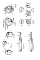
- a mass of abrasive particles i.e., diamond or cubic boron nitride, of from 1 to 200 micron, preferably between 4-8 micron, is mixed with a suitable fugitive binder. such as parafin, etc., and packed into the groove 15, so as to completely fill the groove, including the conical end.
- the blank with the abrasive is then placed in a tubular mold made of molybdenum or other refractory metals, along with a disc of suitable catalytic sintering aid such as cobalt, iron, nickel, etc.
- the diamond is mixed with metals, metal compounds or metal alloy powders of a suitable catalytic sintering aid.
- a cap of this catalytic sintering aid or refractory metal with an internal cone-shaped surface is placed on the mold over the abrasive and the mold is then loaded into a high pressure, high temperature (HP/HT) press.
- the contents of the mold are then subjected to pressures of 45Kbar to 75Kbar and temperatures of 1200°C to 1600°C for approximately 1 to 20 minutes.
- Apparatus and techniques for such sintering are disclosed in U.S. patents 2,941,248; 3,141,746; 3,745,623; and 3,743,489 (incorporated herein by reference).
- the abrasive mass is fully sintered, with the particles bonded to each other and to the carbide, the blank is removed from the press.
- the resultant composite sintered abrasive tip is made up of a cemented carbide cylinder with a vein of fully sintered abrasive particles imbedded in and extending across one end thereof.
- the composite sintered abrasive tip is attached to a shank made of a suitable tough material, such as steel, tungsten carbide, etc., which has high transverse rupture strength and rigidity.
- the shank 15, Fig. 3 is formed or machined with a reduced section 16 which makes up the body of the drill.
- the flat end 12 of the tip is brazed or similarly secured to the similarly flat end 17 of the reduced section.
- helical flutes 18 are then machined or ground in the tip and the reduced section. The flutes begin at the conical end in the cemented carbide on either side of the abrasive vein and then proceed around the tip at the helix angle.
- the abrasive vein forms the web 19 and the lands 20, 21 of the drill as illustrated in Fig. 6.
- the taper of the vein exposes protruding edges 22 and 23 which form the cutting lips of the drill.
- portions of the abrasive vein are exposed and define sections of the flutes.
- the web behind the edges 22 and 23 is provided with a desired angle or rake, either by shaping the cap of the mold in which the tip is sintered or by subsequent grinding.
- ribs 24 and 25 may be formed during the sintering process and then exposed when the carbide is subsequently removed from the remainder of the lands 20 and 21 by grinding.
- the abrasive vein is extremely hard and very difficult and time consuming to grind. Accordingly, it is desireable to mold the abrasive mass and then sinter it, as close as possible, to the finished configuration desired for the drill.
- abrasive vein 26 is imbedded in a shallow groove which extends across the end of the tip 27 and a short distance down the opposite sides.
- the abrasive vein may be discontinuous, being in segments 28 and 29 which are imbedded in groove sections formed in the end of the tip 30 at the opposite extremeties of a diameter thereof. The sections of the groove are formed at the corners of the tip and are deep enough that the abrasive vein is exposed along the sides of the tip as well as across at least portions of the end.
- the edge 31 of both sections of the groove is preferably tapered in the direction of the flute and at the helix angle, so that the leading edges of the abrasive vein segments imbedded therein will accommodate the flutes when they are ground.
- the abrasive vein is located at the extremity of the tip and exposed at the end and along opposite sides thereof. When the flutes are ground and the tip pointed, the abrasive vein forms the cutting surfaces of the drill. In this respect, the great majority of the cutting action, and resultant wear, of the drill occurs at the corners where the abrasive is located.
- Figs. 7 and 8 similarly to Figs. 1 and 2, the abrasive mixture is packed in the groove; the blank and abrasive is placed in a mold and then sintered in a HP/HT press. The tip is then attached to the reduced section of a shank and the body of the drill fluted. The end of the tip is then pointed and finished to provide the finished drill.
Priority Applications (1)
| Application Number | Priority Date | Filing Date | Title |
|---|---|---|---|
| AT84107882T ATE88935T1 (de) | 1983-07-21 | 1984-07-05 | Verfahren zur herstellung eines bohrers fuer leiterplatten. |
Applications Claiming Priority (2)
| Application Number | Priority Date | Filing Date | Title |
|---|---|---|---|
| US51577783A | 1983-07-21 | 1983-07-21 | |
| US515777 | 1995-08-16 |
Publications (3)
| Publication Number | Publication Date |
|---|---|
| EP0132652A2 true EP0132652A2 (de) | 1985-02-13 |
| EP0132652A3 EP0132652A3 (en) | 1985-12-18 |
| EP0132652B1 EP0132652B1 (de) | 1993-05-05 |
Family
ID=24052693
Family Applications (1)
| Application Number | Title | Priority Date | Filing Date |
|---|---|---|---|
| EP84107882A Expired - Lifetime EP0132652B1 (de) | 1983-07-21 | 1984-07-05 | Verfahren zur Herstellung eines Bohrers für Leiterplatten |
Country Status (6)
| Country | Link |
|---|---|
| EP (1) | EP0132652B1 (de) |
| JP (1) | JPS6076905A (de) |
| KR (1) | KR920008585B1 (de) |
| AT (1) | ATE88935T1 (de) |
| CA (1) | CA1233347A (de) |
| DE (1) | DE3486140T2 (de) |
Cited By (13)
| Publication number | Priority date | Publication date | Assignee | Title |
|---|---|---|---|---|
| EP0223474A2 (de) * | 1985-11-04 | 1987-05-27 | De Beers Industrial Diamond Division (Proprietary) Limited | Verfahren zur Herstellung eines Bohrerrohlings |
| US4744705A (en) * | 1986-06-23 | 1988-05-17 | Mitsubishi Kinzoku Kabushiki Kaisha | Twist drill bit |
| US4762445A (en) * | 1985-06-03 | 1988-08-09 | Precorp, Inc. | Composite sintered twist drill |
| FR2654663A1 (fr) * | 1989-11-17 | 1991-05-24 | Diamoutils | Outil de coupe rotatif au diamant, et procede pour sa realisation. |
| US5022801A (en) * | 1990-07-18 | 1991-06-11 | The General Electric Company | CVD diamond coated twist drills |
| FR2656554A1 (fr) * | 1989-12-28 | 1991-07-05 | Snecma | Outil de percage de precision pour materiaux composites. |
| US5065647A (en) * | 1990-08-27 | 1991-11-19 | Ford Motor Company | Bit for drilling cast iron |
| US5273379A (en) * | 1992-01-23 | 1993-12-28 | Gn Tool Co., Ltd. | Blank material for drill and drill therefrom |
| WO1997029877A1 (en) * | 1996-02-15 | 1997-08-21 | Habit Diamond Ltd. | Machining tool and method for forming same |
| US6182533B1 (en) | 1997-08-27 | 2001-02-06 | Klaus Tank | Method of making a drill blank |
| EP1931490B1 (de) | 2005-10-04 | 2015-12-09 | Gühring KG | Spanabtragendes werkzeug |
| US9533398B2 (en) | 2014-08-19 | 2017-01-03 | Us Synthetic Corporation | Positive relief forming of polycrystalline diamond structures and resulting cutting tools |
| US9975185B2 (en) | 2011-06-13 | 2018-05-22 | Element Sux Abrasives S.A. | Twist drill tips, precursor constructions for use in making same, and methods for making and using same |
Families Citing this family (9)
| Publication number | Priority date | Publication date | Assignee | Title |
|---|---|---|---|---|
| JPH0647209B2 (ja) * | 1985-07-13 | 1994-06-22 | 博 石塚 | 超砥粒を含む軸状研削工具ブランクの製造法 |
| JPS63251130A (ja) * | 1987-04-06 | 1988-10-18 | Toshiba Tungaloy Co Ltd | 小径ドリルの製造方法 |
| JPH0563717U (ja) * | 1992-01-31 | 1993-08-24 | 東芝タンガロイ株式会社 | ツイストドリル |
| JP2010260115A (ja) * | 2009-04-30 | 2010-11-18 | Sumitomo Electric Ind Ltd | 繊維強化複合材料用穴あけ工具 |
| DE102009028020B4 (de) | 2009-07-27 | 2011-07-28 | Hilti Aktiengesellschaft | Bohrer und Herstellungsverfahren |
| WO2011084864A2 (en) * | 2009-12-31 | 2011-07-14 | Diamond Innovations, Inc. | Machining tool blank |
| DE102013004679B4 (de) * | 2013-03-19 | 2017-11-23 | Skybrain Vermögensverwaltung GmbH | Vorrichtung und Verfahren zum Bearbeiten von Leiterplatten |
| CN107639273B (zh) * | 2016-07-22 | 2019-05-14 | 创国兴业有限公司 | 钻头结构 |
| JP6655193B2 (ja) * | 2016-09-20 | 2020-02-26 | 本田技研工業株式会社 | Pcdドリルの製造方法 |
Citations (12)
| Publication number | Priority date | Publication date | Assignee | Title |
|---|---|---|---|---|
| DE345911C (de) * | ||||
| DE493860C (de) * | 1930-03-12 | Siemens Schuckertwerke Akt Ges | Verfahren zur Herstellung von Bohrern mit Schneidentraegern aus Hartmetall | |
| US1887372A (en) * | 1928-12-22 | 1932-11-08 | Cleveland Twist Drill Co | Cutting and forming tools, implements, and the like |
| DE594043C (de) * | 1930-05-27 | 1934-03-09 | Fried Krupp Akt Ges | Verbindung hochschnitthaltiger Werkstoffe mit hochlegiertem Stahl (Schnellstahl) durch Loetung mittels einer Zwischenlage |
| US3743489A (en) * | 1971-07-01 | 1973-07-03 | Gen Electric | Abrasive bodies of finely-divided cubic boron nitride crystals |
| US3745623A (en) * | 1971-12-27 | 1973-07-17 | Gen Electric | Diamond tools for machining |
| US4186628A (en) * | 1976-11-30 | 1980-02-05 | General Electric Company | Rotary drill bit and method for making same |
| US4228942A (en) * | 1977-06-24 | 1980-10-21 | Rainer Dietrich | Method of producing abrasive compacts |
| US4334928A (en) * | 1976-12-21 | 1982-06-15 | Sumitomo Electric Industries, Ltd. | Sintered compact for a machining tool and a method of producing the compact |
| EP0054250A2 (de) * | 1980-12-17 | 1982-06-23 | SORTIMAT Creuz & Co. GmbH | Verfahren und Vorrichtung zum Anbringen einer Hartmetallplatte am Kopf eines Spiralbohrers |
| EP0079243A1 (de) * | 1981-11-09 | 1983-05-18 | Sumitomo Electric Industries Limited | Kompaktverbundkörper der einen Presskörper aus Diamant oder Bornitrid enthält |
| DE3232686A1 (de) * | 1982-09-02 | 1984-03-08 | Hartmetallwerkzeugfabrik Andreas Maier GmbH + Co KG, 7959 Schwendi | Rotations-schneidwerkzeug und verfahren zu seiner herstellung |
Family Cites Families (3)
| Publication number | Priority date | Publication date | Assignee | Title |
|---|---|---|---|---|
| JPS5766805A (en) * | 1980-10-06 | 1982-04-23 | Nippon Oil & Fats Co Ltd | Cutting tool of high hardness |
| JPS5870812U (ja) * | 1981-11-06 | 1983-05-13 | 株式会社豊田中央研究所 | ダイヤモンドドリル |
| JPS5879879A (ja) * | 1981-11-09 | 1983-05-13 | 住友電気工業株式会社 | 複合ダイヤモンド焼結体 |
-
1984
- 1984-07-03 CA CA000457962A patent/CA1233347A/en not_active Expired
- 1984-07-05 DE DE8484107882T patent/DE3486140T2/de not_active Expired - Fee Related
- 1984-07-05 AT AT84107882T patent/ATE88935T1/de not_active IP Right Cessation
- 1984-07-05 EP EP84107882A patent/EP0132652B1/de not_active Expired - Lifetime
- 1984-07-20 KR KR1019840004307A patent/KR920008585B1/ko not_active IP Right Cessation
- 1984-07-20 JP JP59149795A patent/JPS6076905A/ja active Granted
Patent Citations (12)
| Publication number | Priority date | Publication date | Assignee | Title |
|---|---|---|---|---|
| DE345911C (de) * | ||||
| DE493860C (de) * | 1930-03-12 | Siemens Schuckertwerke Akt Ges | Verfahren zur Herstellung von Bohrern mit Schneidentraegern aus Hartmetall | |
| US1887372A (en) * | 1928-12-22 | 1932-11-08 | Cleveland Twist Drill Co | Cutting and forming tools, implements, and the like |
| DE594043C (de) * | 1930-05-27 | 1934-03-09 | Fried Krupp Akt Ges | Verbindung hochschnitthaltiger Werkstoffe mit hochlegiertem Stahl (Schnellstahl) durch Loetung mittels einer Zwischenlage |
| US3743489A (en) * | 1971-07-01 | 1973-07-03 | Gen Electric | Abrasive bodies of finely-divided cubic boron nitride crystals |
| US3745623A (en) * | 1971-12-27 | 1973-07-17 | Gen Electric | Diamond tools for machining |
| US4186628A (en) * | 1976-11-30 | 1980-02-05 | General Electric Company | Rotary drill bit and method for making same |
| US4334928A (en) * | 1976-12-21 | 1982-06-15 | Sumitomo Electric Industries, Ltd. | Sintered compact for a machining tool and a method of producing the compact |
| US4228942A (en) * | 1977-06-24 | 1980-10-21 | Rainer Dietrich | Method of producing abrasive compacts |
| EP0054250A2 (de) * | 1980-12-17 | 1982-06-23 | SORTIMAT Creuz & Co. GmbH | Verfahren und Vorrichtung zum Anbringen einer Hartmetallplatte am Kopf eines Spiralbohrers |
| EP0079243A1 (de) * | 1981-11-09 | 1983-05-18 | Sumitomo Electric Industries Limited | Kompaktverbundkörper der einen Presskörper aus Diamant oder Bornitrid enthält |
| DE3232686A1 (de) * | 1982-09-02 | 1984-03-08 | Hartmetallwerkzeugfabrik Andreas Maier GmbH + Co KG, 7959 Schwendi | Rotations-schneidwerkzeug und verfahren zu seiner herstellung |
Cited By (18)
| Publication number | Priority date | Publication date | Assignee | Title |
|---|---|---|---|---|
| US4762445A (en) * | 1985-06-03 | 1988-08-09 | Precorp, Inc. | Composite sintered twist drill |
| EP0223474A3 (en) * | 1985-11-04 | 1988-11-09 | De Beers Industrial Diamond Division (Proprietary) Limited | Drill blanks |
| EP0223474A2 (de) * | 1985-11-04 | 1987-05-27 | De Beers Industrial Diamond Division (Proprietary) Limited | Verfahren zur Herstellung eines Bohrerrohlings |
| US4744705A (en) * | 1986-06-23 | 1988-05-17 | Mitsubishi Kinzoku Kabushiki Kaisha | Twist drill bit |
| FR2654663A1 (fr) * | 1989-11-17 | 1991-05-24 | Diamoutils | Outil de coupe rotatif au diamant, et procede pour sa realisation. |
| FR2656554A1 (fr) * | 1989-12-28 | 1991-07-05 | Snecma | Outil de percage de precision pour materiaux composites. |
| EP0467114A1 (de) * | 1990-07-18 | 1992-01-22 | General Electric Company | CVD-Diamant beschichtete Spiralbohrer |
| US5022801A (en) * | 1990-07-18 | 1991-06-11 | The General Electric Company | CVD diamond coated twist drills |
| US5065647A (en) * | 1990-08-27 | 1991-11-19 | Ford Motor Company | Bit for drilling cast iron |
| US5273379A (en) * | 1992-01-23 | 1993-12-28 | Gn Tool Co., Ltd. | Blank material for drill and drill therefrom |
| WO1997029877A1 (en) * | 1996-02-15 | 1997-08-21 | Habit Diamond Ltd. | Machining tool and method for forming same |
| US6132148A (en) * | 1996-02-15 | 2000-10-17 | Habit Diamond Limited | Machining tool and method for forming same |
| CN1066990C (zh) * | 1996-02-15 | 2001-06-13 | 哈比特钻石有限公司 | 切削刀具及其制造方法 |
| US6182533B1 (en) | 1997-08-27 | 2001-02-06 | Klaus Tank | Method of making a drill blank |
| EP1931490B1 (de) | 2005-10-04 | 2015-12-09 | Gühring KG | Spanabtragendes werkzeug |
| US9975185B2 (en) | 2011-06-13 | 2018-05-22 | Element Sux Abrasives S.A. | Twist drill tips, precursor constructions for use in making same, and methods for making and using same |
| US9533398B2 (en) | 2014-08-19 | 2017-01-03 | Us Synthetic Corporation | Positive relief forming of polycrystalline diamond structures and resulting cutting tools |
| US11667011B2 (en) | 2014-08-19 | 2023-06-06 | Us Synthetic Corporation | Methods of making a polycrystalline diamond structure |
Also Published As
| Publication number | Publication date |
|---|---|
| JPS6076905A (ja) | 1985-05-01 |
| EP0132652A3 (en) | 1985-12-18 |
| DE3486140T2 (de) | 1993-08-19 |
| DE3486140D1 (de) | 1993-06-09 |
| CA1233347A (en) | 1988-03-01 |
| KR920008585B1 (ko) | 1992-10-02 |
| KR850001046A (ko) | 1985-03-14 |
| EP0132652B1 (de) | 1993-05-05 |
| ATE88935T1 (de) | 1993-05-15 |
| JPH0355246B2 (de) | 1991-08-22 |
Similar Documents
| Publication | Publication Date | Title |
|---|---|---|
| US4713286A (en) | Printed circuit board drill and method of manufacture | |
| EP0132652B1 (de) | Verfahren zur Herstellung eines Bohrers für Leiterplatten | |
| US4762445A (en) | Composite sintered twist drill | |
| CA1286510C (en) | Stick of composite materials and process for preparation thereof | |
| KR100749994B1 (ko) | 복합 회전도구 및 도구제작 방법 | |
| EP0560951B1 (de) | Verschleissfeste Werkzeuge | |
| US4991467A (en) | Diamond twist drill blank | |
| EP2533922B1 (de) | Superharte werkzeugspitze und deren verwendung | |
| US5628837A (en) | Surface decarburization of a drill bit having a refined primary cutting edge | |
| KR20140023382A (ko) | 비틀림 드릴 팁, 그 제조에 사용하기 위한 전구체 구조물, 및 그 제조와 사용 방법 | |
| CN101128644A (zh) | 带有固定切削结构的钻头 | |
| KR101469402B1 (ko) | 회전 드릴용 비트의 제조 방법 | |
| US20080080938A1 (en) | Cutting tool and manufacture method for the same | |
| EP0690758B1 (de) | Oberflächen-entkohlung eines bohrer mit rafinierter primärschneidkante | |
| EP3569351A1 (de) | Geaderter werkzeugrohling und bohrer | |
| JP3606742B2 (ja) | 台金にクリアランスを有するコアビット | |
| JPH0742488B2 (ja) | 複合焼結材料棒状体の製造方法 | |
| JPH0525617B2 (de) | ||
| JPS60264371A (ja) | 複合焼結材料円柱体 |
Legal Events
| Date | Code | Title | Description |
|---|---|---|---|
| PUAI | Public reference made under article 153(3) epc to a published international application that has entered the european phase |
Free format text: ORIGINAL CODE: 0009012 |
|
| AK | Designated contracting states |
Designated state(s): AT BE CH DE FR GB IT LI NL SE |
|
| PUAL | Search report despatched |
Free format text: ORIGINAL CODE: 0009013 |
|
| AK | Designated contracting states |
Designated state(s): AT BE CH DE FR GB IT LI NL SE |
|
| 17P | Request for examination filed |
Effective date: 19860613 |
|
| 17Q | First examination report despatched |
Effective date: 19870908 |
|
| RAP1 | Party data changed (applicant data changed or rights of an application transferred) |
Owner name: PRECORP INC. |
|
| GRAA | (expected) grant |
Free format text: ORIGINAL CODE: 0009210 |
|
| AK | Designated contracting states |
Kind code of ref document: B1 Designated state(s): AT BE CH DE FR GB IT LI NL SE |
|
| PG25 | Lapsed in a contracting state [announced via postgrant information from national office to epo] |
Ref country code: SE Effective date: 19930505 Ref country code: NL Effective date: 19930505 Ref country code: LI Effective date: 19930505 Ref country code: IT Free format text: LAPSE BECAUSE OF FAILURE TO SUBMIT A TRANSLATION OF THE DESCRIPTION OR TO PAY THE FEE WITHIN THE PRESCRIBED TIME-LIMIT;WARNING: LAPSES OF ITALIAN PATENTS WITH EFFECTIVE DATE BEFORE 2007 MAY HAVE OCCURRED AT ANY TIME BEFORE 2007. THE CORRECT EFFECTIVE DATE MAY BE DIFFERENT FROM THE ONE RECORDED. Effective date: 19930505 Ref country code: CH Effective date: 19930505 Ref country code: BE Effective date: 19930505 Ref country code: AT Effective date: 19930505 |
|
| REF | Corresponds to: |
Ref document number: 88935 Country of ref document: AT Date of ref document: 19930515 Kind code of ref document: T |
|
| REF | Corresponds to: |
Ref document number: 3486140 Country of ref document: DE Date of ref document: 19930609 |
|
| ET | Fr: translation filed | ||
| REG | Reference to a national code |
Ref country code: CH Ref legal event code: PL |
|
| NLV1 | Nl: lapsed or annulled due to failure to fulfill the requirements of art. 29p and 29m of the patents act | ||
| PLBE | No opposition filed within time limit |
Free format text: ORIGINAL CODE: 0009261 |
|
| STAA | Information on the status of an ep patent application or granted ep patent |
Free format text: STATUS: NO OPPOSITION FILED WITHIN TIME LIMIT |
|
| 26N | No opposition filed | ||
| PGFP | Annual fee paid to national office [announced via postgrant information from national office to epo] |
Ref country code: GB Payment date: 19970620 Year of fee payment: 14 |
|
| PGFP | Annual fee paid to national office [announced via postgrant information from national office to epo] |
Ref country code: FR Payment date: 19970711 Year of fee payment: 14 |
|
| PGFP | Annual fee paid to national office [announced via postgrant information from national office to epo] |
Ref country code: DE Payment date: 19970729 Year of fee payment: 14 |
|
| PG25 | Lapsed in a contracting state [announced via postgrant information from national office to epo] |
Ref country code: GB Free format text: LAPSE BECAUSE OF NON-PAYMENT OF DUE FEES Effective date: 19980705 |
|
| GBPC | Gb: european patent ceased through non-payment of renewal fee |
Effective date: 19980705 |
|
| PG25 | Lapsed in a contracting state [announced via postgrant information from national office to epo] |
Ref country code: FR Free format text: LAPSE BECAUSE OF NON-PAYMENT OF DUE FEES Effective date: 19990331 |
|
| PG25 | Lapsed in a contracting state [announced via postgrant information from national office to epo] |
Ref country code: DE Free format text: LAPSE BECAUSE OF NON-PAYMENT OF DUE FEES Effective date: 19990501 |
|
| REG | Reference to a national code |
Ref country code: FR Ref legal event code: ST |