EP0078538B1 - Blau-emittierender Leuchtstoff mit langer Nachleuchtzeit und eine denselben verwendende, durch Elektronen angeregte Anzeigevorrichtung - Google Patents
Blau-emittierender Leuchtstoff mit langer Nachleuchtzeit und eine denselben verwendende, durch Elektronen angeregte Anzeigevorrichtung Download PDFInfo
- Publication number
- EP0078538B1 EP0078538B1 EP82110097A EP82110097A EP0078538B1 EP 0078538 B1 EP0078538 B1 EP 0078538B1 EP 82110097 A EP82110097 A EP 82110097A EP 82110097 A EP82110097 A EP 82110097A EP 0078538 B1 EP0078538 B1 EP 0078538B1
- Authority
- EP
- European Patent Office
- Prior art keywords
- phosphor
- phosphors
- activator
- sulfur
- afterglow
- Prior art date
- Legal status (The legal status is an assumption and is not a legal conclusion. Google has not performed a legal analysis and makes no representation as to the accuracy of the status listed.)
- Expired
Links
Images


Classifications
-
- C—CHEMISTRY; METALLURGY
- C09—DYES; PAINTS; POLISHES; NATURAL RESINS; ADHESIVES; COMPOSITIONS NOT OTHERWISE PROVIDED FOR; APPLICATIONS OF MATERIALS NOT OTHERWISE PROVIDED FOR
- C09K—MATERIALS FOR MISCELLANEOUS APPLICATIONS, NOT PROVIDED FOR ELSEWHERE
- C09K11/00—Luminescent, e.g. electroluminescent, chemiluminescent materials
- C09K11/08—Luminescent, e.g. electroluminescent, chemiluminescent materials containing inorganic luminescent materials
- C09K11/64—Luminescent, e.g. electroluminescent, chemiluminescent materials containing inorganic luminescent materials containing aluminium
- C09K11/641—Chalcogenides
- C09K11/642—Chalcogenides with zinc or cadmium
-
- H—ELECTRICITY
- H01—ELECTRIC ELEMENTS
- H01J—ELECTRIC DISCHARGE TUBES OR DISCHARGE LAMPS
- H01J29/00—Details of cathode-ray tubes or of electron-beam tubes of the types covered by group H01J31/00
- H01J29/02—Electrodes; Screens; Mounting, supporting, spacing or insulating thereof
- H01J29/10—Screens on or from which an image or pattern is formed, picked up, converted or stored
- H01J29/18—Luminescent screens
- H01J29/20—Luminescent screens characterised by the luminescent material
-
- H—ELECTRICITY
- H01—ELECTRIC ELEMENTS
- H01J—ELECTRIC DISCHARGE TUBES OR DISCHARGE LAMPS
- H01J29/00—Details of cathode-ray tubes or of electron-beam tubes of the types covered by group H01J31/00
- H01J29/02—Electrodes; Screens; Mounting, supporting, spacing or insulating thereof
- H01J29/10—Screens on or from which an image or pattern is formed, picked up, converted or stored
- H01J29/18—Luminescent screens
- H01J29/187—Luminescent screens screens with more than one luminescent material (as mixtures for the treatment of the screens)
-
- H—ELECTRICITY
- H01—ELECTRIC ELEMENTS
- H01J—ELECTRIC DISCHARGE TUBES OR DISCHARGE LAMPS
- H01J29/00—Details of cathode-ray tubes or of electron-beam tubes of the types covered by group H01J31/00
- H01J29/02—Electrodes; Screens; Mounting, supporting, spacing or insulating thereof
- H01J29/10—Screens on or from which an image or pattern is formed, picked up, converted or stored
- H01J29/18—Luminescent screens
- H01J29/30—Luminescent screens with luminescent material discontinuously arranged, e.g. in dots, in lines
- H01J29/32—Luminescent screens with luminescent material discontinuously arranged, e.g. in dots, in lines with adjacent dots or lines of different luminescent material, e.g. for colour television
Definitions
- This invention relates to a zinc sulfide phosphor which emits blue light under excitation by an electron-beam and exhibits long afterglow, and to an electron excited fluorescent display device using the same.
- a cathode-ray tube having a high resolution for terminal display devices of a computer or display devices of an air traffic control system in which fine characters and/or patterns are displayed.
- the resolution of the cathode-ray tube can be effectively improved by reducing the frame frequency thereof.
- the frame frequency of the cathode-ray tube which is about 55 Hz in case of the standard cathode-ray tube such as those for television screen, to about 30 Hz
- the signal frequency band can be enlarged twice as wide as that of the standard cathode-ray tube, or the video frequency band can be narrowed to half of that of the standard cathode-ray tube, whereby the resolution can be improved.
- the video frequency band of the driving circuit of the cathode-ray tube is determined depending on the product of the frame frequency and the signal frequency band.
- the fluorescent screen of the cathode-ray tube having such a high resolution must be formed of phosphors which exhibits long afterglow characteristics. This is because if the fluorescent screen of the cathode-ray tube having a high resolution is formed of phosphors exhibiting short afterglow characteristics, flicker is apt to occur in the image on the screen due to low scanning speed. Generally, it is required for the phosphors forming the cathode-ray tube having such a high resolution that the afterglow time is longer than that of the phosphors forming the standard cathode-ray tube by several tens to several hundreds times.
- afterglow time is defined as the time within which the emission intensity of the phosphor reduces to 10% of that under excitation by an electron beam having a current density of 1 ⁇ A/cm 2 after the excitation is interrupted, that is, the term "afterglow time” means 10% afterglow time in this specification.
- a manganese activated zinc silicate green emitting phosphor Zn z Si0 4 : Mn
- a manganese and arsenic activated zinc silicate green emitting phosphor Zn 2 Si0 4 :Mn, As
- a manganese activated zinc magnesium orthophosphate red emitting phosphor [(Zn, Mg) 3 (PO 4 ) 2 :Mn])
- a manganese activated zinc orthophosphate red emitting phosphor Zn 3 (P0 4 ) 2 :Mn
- a manganese activated magnesium silicate red emitting phosphor MgSi0 3 :Mn
- a manganese and lead activated calcium silicate orange emitting phosphor CaSi0 3 :Mn, Pb
- a manganese activated cadmium chlorophosphate orange emitting phosphor 3Cd 3 (PO
- the fluorescent screen of a black-and-white cathode-ray tube is a white emitting fluorescent layer formed of a mixture of red, green and blue emitting phosphors
- the fluorescent screen of a color cathode-ray tube is formed of a plurality of regularly arranged light emitting element trios, each trio comprising red, green and blue emitting elements which are generally in the form of a dot or a stripe.
- the aforesaid long afterglow green emitting phosphors can be used as the green emitting component of the high resolution black-and-white or color cathode-ray tube, and aforesaid red or orange emitting phosphors can be used as the red emitting component of the same.
- the light blue emitting phosphor is a mixture of phosphors having different luminescent colors, color shading is apt to occur in its luminescent color and its color purity is low.
- the primary object of the present invention is to provide a blue emitting phosphor which exhibits long afterglow and is particularly suitable for use in a high resolution cathode-ray tube, thereby promoting the spread of such high resolution cathode-ray tubes.
- Another object of the present invention is to provide a long afterglow phosphor which can emit blue light of higher luminance.
- Still another object of the present invention is to provide a long afterglow phosphor which can emit blue light of high color purity.
- Still another object of the present invention is to provide an electron excited fluorescent display device having a fluorescent screen formed of phosphors exhibiting long afterglow.
- Still another object of the present invention is to provide a black-and-white or color cathode-ray tube having a high resolution.
- Still another object of the present invention is to provide a high resolution cathode-ray tube having a fluorescent screen free from color shading in the blue component of its afterglow.
- Still another object of the present invention is to provide a high resolution cathode-ray tube having a fluorescent screen free from color drift in the blue component of its afterglow.
- the inventors of the present invention conducted various investigations to elongate the afterglow time of the aforesaid ZnS:Ag, X phosphor which has been in wide use as a blue emitting phosphor, and as the result of the investigations it is found that a blue emitting phosphor of which 10% afterglow time is remarkedly longer than that of the known ZnS:Ag, X phosphor can be obtained by activating zinc sulfide with a proper amount of at least one of gallium and indium in addition to silver and X wherein X has the same significance as defined above.
- the present invention is based on this discovery in one aspect.
- the present invention is based on a discovery that a light blue emitting phosphor the luminance of which is higher than that of the known light blue emitting phosphor and the afterglow time of which is remarkably longer than the same can be obtained by activating zinc sulfide with a proper amount of at least one of gallium and indium in addition to a proper amount of silver and X and a small amount of at least one of copper and gold wherein X has the same significance as defined above.
- the present invention is based on a discovery that the luminance of said long afterglow blue emitting phosphor is lowered as the activating amount of gallium and/or indium is increased and that the lowering of the luminance of the long afterglow blue emitting phosphor can be substantially refrained without significantly affecting the luminescent color and the afterglow characteristics by using as the host material green powder of zinc sulfide which is mixed with a large amount of sulfur during refining and by mixing a trace amount of sulfur in the resulting phosphor.
- a superior display can be obtained by an electron excited fluorescent display device having a fluorescent screen including the long afterglow blue emitting phosphor according to the present invention as the blue emitting component.
- a display with a very high resolution can be obtained by a high resolution cathode-ray tube having a fluorescent screen which includes at least one kind of the long afterglow blue emitting phosphors of the present invention of which afterglow time is specified as the major component of the blue emitting component, a red emitting phosphor of which afterglow time is specified and a green emitting phosphor of which afterglow time is specified.
- zinc sulfide blue emitting phosphors exhibiting long afterglow which comprise zinc sulfide as the host material, silver as a first activator, at least one of gold and copper as a second activator, at least one of gallium and indium as a first co-activator and at least one of chlorine, bromine, iodine, fluorine and aluminum as a second activator, the amounts of the first and second activators and the first and second co-activators being 5x10- 4 to 10- 1 %, 0 to 2 x10- 2 %, 10- 6 to 10- 1 % and 5 ⁇ 10 -6 to 5x10- 2 % by weight on the basis of the weight of the zinc sulfide host material, respectively.
- these phosphors will be referred to as "the phosphors without sulfur”.
- zinc sulfide blue emitting phosphors exhibiting long afterglow which comprises zinc sulfide as the host material, silver as a first activator, at least one of gold and copper as a second activator, at least one of gallium and indium as a first co-activator, at least one of chlorine, bromine, iodine fluorine and aluminium as a second co-activator and sulfur, the amounts of the first and second activators, the first and second co-activators and sulfur being 5x 10 -4 to 10 -1 %, 0 to 2 ⁇ 10 -2 %, 10- 6 to 10-1%, 5 ⁇ 10 -6 to 5x10⁻²%, and 10 -5 to 8 ⁇ 10 -1 % by weight on the basis of the weight of the zinc sulfide host material.
- these phosphors will be referred to as phosphors with sulfur.
- an electron excited fluorescent display device having at least one kind of the long afterglow blue emitting phosphors of the present invention as the blue emitting component.
- the electron excited fluorescent display device is a high resolution cathode-ray tube having a fluorescent screen formed of
- the afterglow time of the zinc sulfide blue emitting phosphor of the present invention after interruption of excitation by an electron beam, an ultraviolet ray and the like is longer than that of the conventional ZnS:Ag, X blue emitting phosphor by several tens to several hundreds times.
- the main crystalline phase of the phosphors of the present invention forms either a cubic system or a hexagonal system depending on the firing temperature.
- the phosphors having a main crystal phase of a cubic system exhibit higher luminance than those having a main crystal phase of a hexagonal system.
- at least one of gallium and indium is added by an amount within a range proper to make a phosphor exhibiting further higher luminance with high color purity, the former exhibits longer afterglow than the latter. Accordingly, among the phosphors of the present invention, phosphors having a main crystal line phase of a cubic system are more suitable for the high resolution cathode-ray tube than those having a main crystal line phase of a hexagonal system
- a large amount of sulfur is mixed in the green powder of zinc sulfide during refining.
- the green powder of zinc sulfide mixed with the large amount of sulfur can be prepared adding ammonium sulfide to weak acidic, e.g., pH 6 to 4, aqueous solution of zinc sulfate maintaining the pH value of the aqueous solution, thereby precipitating zinc sulfide.
- the amount of sulfur existing in excess of stoichiometric amount in the green powder of zinc sulfide thus obtained depends on the pH value of said aqueous solution and increases as the pH value is lowered.
- green powder of zinc sulfide precipitated in aqueous solution with pH 6 to 4 includes sulfur in a weight of which is several tenths to several tens percent by weight on the basis of the weight of zinc sulfide in excess of the stoichiometric weight of sulfur.
- the excess sulfur is almost lost during firing process and only a part thereof remains in the phoshpor obtained. Accordingly, the amount of the excess sulfur contained in the green powder of zinc sulfide is selected taking into account the firing temperature and the firing time so that there remains a desired weight of sulfur which should be in the range of 10- 5 % to 8 ⁇ 10 -1 % by weight on the basis of the weight of zinc sulfide host material in the phosphor obtained.
- Said four (1 to 4) raw materials are used in a weight ratio which provides desired weight % of the first and second activators and the first co-activator with respect to the weight of zinc sulfide in the raw material of the host material which should be in the ranges of 5 ⁇ 10 -4 to 10-'%, 0 to 2x10- Z %, and 10- 6 to 10-1% by weight on the basis of the weight of zinc sulfide, respectively.
- the raw material of the second co-activator must be used in a weight ratio which provides desired weight % of the second co-activator in the phosphor obtained which should be in the range of 5 ⁇ 10 -6 to 5 ⁇ 10 -2 % on the basis of the weight of zinc sulfide.
- halogen contained in the raw material of the second co-activator is almost lost during firing process and only a very small part thereof remains in the phosphor obtained, though aluminium in the raw material of the second co-activator all remains in the phosphor obtained. Accordingly, halide of the alkaline metals or alkaline earth metals must be used in an amount which includes several tens to several hundreds times as much halogen as the desired activating amount depending on the firing temperature and the like.
- halide When halide is used as the raw materials of the first activator, the second activator, the first co-activator and/or aluminum, a part of the required amount of halogen is also provided by such raw materials.
- Halide of the alkaline metals or the alkaline earth metals acts as flux as well as the agent for providing halogen.
- the raw materials of the first and second activators and the first and second co-activators may be added in the form of solutions to the raw material of the zinc sulfide host material. In this case the raw material mixture obtained should be sufficiently dried.
- the amount of the second activator may be zero %, of course, the raw material of the second activator may be omitted.
- the raw material mixture is placed in a heat resistant container such as a quartz crucible and a quartz tube and fired.
- the firing is performed in a sulfide atmosphere such as a hydrogen sulfide atmosphere, a sulfur vapor atmosphere and a carbon disulfide atmosphere.
- a proper firing temperature range is 600 to 1200°C.
- the firing temperature is preferably in the range-of 600 to 1050°C, and more preferably in the range of 800 to 1050°C.
- the firing time depends on the firing temperature, the amount of the raw material mixture in the container, but a proper time is 0.5 to 7 hours in the aforesaid temperature range. After the firing, the fired product is subjected to treatments generally employed in the production of phosphor such as washing, drying and sieving to provide the desired phosphor.
- Both the phosphors with sulfur and the phosphors without sulfur of the present invention can be produced by the process described above.
- the phosphors without sulfur emits blue light of high luminance equivalent to that of the conventional ZnS:Ag, X phosphor under excitation by an electron beam, ultraviolet rays and the like.
- the 10% afterglow of the former is several tens to several hundreds times longer than that of the latter depending on the activating amount of the first co-activator, gallium and/or indium.
- the afterglow characteristics of the phosphor without sulfur changes depending on the activating amount of the first co-activator under the presence of the second co-activator, and at the same time the activating amount of the first co-activator influences the luminace of emission and the color purity.
- the luminance of emission and the color purity of the phosphors without sulfur is lowered as the activating amount of the first co-activator increases.
- the luminance of emission of the phosphors with sulfur is several to 10% higher than that of the phosphors without sulfur. Further, the luminance of emission of the phosphor having a main crystalline phase of a cubic system is 1.3 times to twice higher than the same of the phosphor having a main crystalline phase of a hexagonal system.
- Figures 1 to 15 show various characteristics of phosphors in accordance with various embodiments of the present invention compared with those of the conventional ZnS:Ag, X phosphor.
- the compositions of the phosphors other than zinc sulfide are given in the following table.
- the amount of each activator, co-activator or sulfur will be given by weight % on the basis of the weight of zinc sulfide, hereinbelow.
- Figure 1 shows emission spectra of a conventional ZnS:Ag, CI phosphor having a main crystalline phase of a cubic system (Phosphor #1) and ZnS:Ag, Ga, CI Phosphors in accordance with the present inventin (phosphors #2 to #4).
- the amounts of the Ag, Ga and CI in the phosphors #1 to #4 are given in the above table and phosphor #3 has a main crystalline phase of a hexagonal system, the other phosphors having a main crystalline phase of a cubic system.
- the activating amounts of Ag and CI in the phosphors #2 to #4 are equal to those in the conventional phosphor (#1).
- lines a to d show emission spectra of the phosphors #1 to #4, respectively.
- the phosphors #2 to #4 in accordance with the present invention emit blue light like the conventional phosphor #1.
- the half-width of the emission spectrum is enlarged and the color purity is lowered, as can be seen by comparing the finest and dwith each other.
- the half-width of the emission spectrum of the phosphor #2 activated by 10- 2 % Ga is narrower than the same of the conventional phosphor #1, and accordingly the intensity of luminescent color of the former is higher than the latter.
- Figure 2 shows emission spectra of the conventional ZnS:Ag, CI phosphor having a main crystalline phase of a cubic system (phosphor #1) and ZnS:Ag, In, CI phosphors in accordance with the present invention (phosphors #5 to #7).
- the amounts of Ag, In and CI in the phosphors #5 to #7 are given in the above table and phosphor #6 has a main crystalline phase of a hexagonal system, the other phosphors having a main crystalline phase of a cubic system.
- the activating amounts of Ag and CI in the phosphors #5 to #7 are equal to those in the conventional phosphor (#1).
- lines a to d show emission spectra of the phosphors #5 to #7, respectively.
- the phosphors #5 to #7 in accordance with the present invention emit blue light like the conventional phosphor #1.
- the half-width of the emission spectrum is enlarged and the color purity is lowered, as can be seen by comparing the lines b and d with each other.
- the half-width of the emission spectrum of the phosphor #5 activated by 10- Z % In is narrower than the same of the conventional phosphor #1, and accordingly the color purity of the former is higher than the latter.
- the emission spectrum of the phosphor #5 having the main crystalline phase of a cubic system slightly shifts toward the longer wave length side with respect to the same of the phosphor #6 having the main crystalline phase of a hexagonal system.
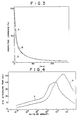
- Figure 3 shows the afterglow characteristics of phosphors in accordance with the present invention and the conventional ZnS:Ag, X phosphor.
- line a shows the afterglow characteristics of said conventional phosphor #1
- line b shows the same of said phosphor #2 in accordance with the present invention
- line c shows the same of a ZnS:Ag, In, CI phosphor #8 in accordance with the present invention.
- the activating amounts of Ag and CI of the phosphors #2 and #8 are equal to those of the phosphor #1.
- the phosphor #2 is further activated with 10- 2 % Ga
- the phosphor #8 is further activated with 2 ⁇ 10 -3 % In as shown in the above table.
- These three phosphors #1, #2 and #8 all have a main crystalline phase of a cubic system.
- the afterglow time of either the phosphors #2 or #8 is remarkably longer than that of the conventional phosphor #1. That is, the afterglow time of the conventional phosphor #1 is about 150 ⁇ sec, while those of the phosphor #2 and #8 are about 40 ms, the latter being more than two hundreds and fifty times longer than the former.
- Figure 4 shows the relation between the activating amount of Ga and the 10% afterglow time in ZnS:Ag, Ga, CI phosphors of the present invention.
- line a shows said relation in a phosphor which contains therein 10 -2 % Ag and 10 -4 % Cl and has a main crystalline phase of a cubic system
- line b shows the relation in a phosphor which contains therein equal amounts of Ag and CI to the above-mentioned values but has a main crystalline phase of a hexagonal system rather than a cubic system.
- the circle on the ordinate indicates the afterglow time of the conventional phosphor #1, i.e., about 150 psec.
- the phosphor #1 contains the same amounts of Ag and CI as the above-mentioned values.
- the 10% afterglow time of the phosphors of the present invention activated with 10- 6 % to 5 ⁇ 10 -1 % Ga is several tens to several hundred times longer than that of the conventional ZnS:Ag, X phosphor irrespective of its main crystalline phase.
- the phosphors of the present invention activated with 5x10- 4 to 10 -1 % Ga exhibit very long afterglow.
- the activating amount of Ga be in the range of 5x 10- 6 to 10- 3 %.
- the 10% afterglow time of the phosphors of the present invention in which the activating amount of Ga is in this range is about 5 to 30 ms, which is sufficient for use in the high resolution cathode-ray tube.
- those having a main crystalline phase of a cubic system exhibit higher luminance of emission than those having a main crystalline phase of a hexagonal system. Further, the former exhibits longer 10% afterglow time than the latter when the activating amount of Ga is in said preferred range as is clear from Figure 4. Therefore, among the phosphors of the present invention, those having a main crystalline phase of a cubic system are more preferred for use in the high resolution cathode-ray tube than those having a main crystalline system of a hexagonal system. Particularly, those which have a main crystalline phase of a cubic system and at the same time are activated with 5 ⁇ 10 -6 to 10- 3 % Ga are most preferred for use in the high resolution cathode-ray tube.
- Figure 4 is related to the phosphors of the present invention containing therein CI as the second co-activator, it has been confirmed that the relation between the amount of activating Ga and the 10% afterglow time in case of phoshpors having the second co-activator other than CI is similar to that shown in Figure 4.
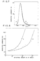
- Figure 5 shows the relation between the activating amount of In and the 10% afterglow time in a ZnS:Ag, In, Cl phosphor of the present invention which contains therein 10 -2 % Ag and 10- 4 % CI and has a main crystalline phase of a cubic system.
- the circle on the ordinate indicates the afterglow time of the conventional phosphor #1, i.e., about 150 usec.
- the phosphor #1 contains the same amounts of Ag and CI as the above-mentioned values.
- the 10% afterglow time of the phosphor of the present invention activated with 10- 6 to 10 -1 % In is several tens to several hundreds times longer than that of the conventional ZnS:Ag, X phosphor.
- the phosphor of the present invention activated with 5 ⁇ 10 -4 to 10 -1 % In exhibit very long afterglow.
- the amount of In is increased by a large amount (to 2 ⁇ 10 -2 % or more)
- the color purity is lowered as described above.
- the 10% afterglow time is extended, the luminance of emission is lowered.
- the activating amount of In is preferably in the range of 5 ⁇ 10 16 to 10 -2 % and more preferably in the range of 5 ⁇ 10 -6 to 10 -3 %.
- the 10% afterglow time of the phosphors of the present invention in which the activating amount of In is in this range is about 5 to 55 ms, which is sufficient for use in the high resolutin cathode-ray tube.
- the graph of Figure 5 is related to the phosphor of the present invention having a main crystalline phase of a cubic system, it has been confirmed that the relation between the amount of activating In and the 10% afterglow in case of phosphors having a main crystalline phase of a hexagonal system is similar to that shown in Figure 5. That is, the phosphors of the present invention having a main crystalline phase of a hexagonal system and activated with 10 -6 to 10 -1 % In exhibit 10% afterglow time several tens to several hundreds times longer than that of the conventional ZnS:Ag, X phosphor. Particularly, when activated with 5 ⁇ 10 -4 to 10 -1 % In, the phosphors exhibit very long 10% afterglow time.
- the 10% afterglow time of the phosphors having a main crystalline phase of a hexagonal system is shorter than that of those having a main crystalline phase of a cubic system.
- those having a main crystalline phase of a cubic system exhibit higher luminance of emission than those having a main crystalline phase of a hexagonal system. Further, the former exhibits longer 10% afterglow time than the latter when the activating amount of In is in said preferred range.
- those having a main crystalline phase of a cubic system are more preferred for use in the high resolution cathode-ray tube than those having a main crystalline system of a hexagonal system.
- those which have a main crystalline phase of a cubic system and at the same time are activated with 5x 10- 6 to 10 -2 % In are most preferred for use in the high resolution cathode-ray tube.
- Figure 5 is related to the phosphors of the present invention containing therein CI as the second co-activator, it has been confirmed that the relation between the amount of activating In and the 10% afterglow time in case of phosphors having the second co-activator other than CI is similar to that shown in Figure 5...
- Figure 6 shows emission spectra of the conventional ZnS:Ag, CI phosphor having a main crystalline phase of a cubic system (phosphor #1) and phosphors in accordance with the present invention (phosphors #9 and #10).
- the compositions of the phosphors #1, #9 and #10 are given in the above table and the #1, #9 and #10 all have a main crystalline phase of a cubic system.
- the activating amounts of Ag and CI in the phosphors #9 and #10 are equal to those in the conventional phosphor (#1), but the phosphor #9 is further activated with 10 -2 % Ga and 2 ⁇ 10 -4 % Cu, and the phosphor #10 is further activated with 10- 2 % Ga and 1.5x10- 3 % Au.
- Figure 6 lines a to c show emission spectra of the phosphors #1, #9 and #10, respectively.
- the phosphors #9 (line b) and #10 (line c) in accordance with the present invention emit blue light like the conventional phosphor #1 (line a).
- the emission spectrum of a phosphor of this type having a main crystalline phase of a hexagonal system is not shown the emission spectrum of the phosphors having a main crystalline phase of a cubic system slightly shifts toward the longer wave length side with respect to the same of the phosphor having a main crystalline phase of a hexagonal system whereby the former exhibits higher color purity than that of the latter.
- Figure 7 shows emission spectra of the conventional ZnS:Ag, CI phosphor #1 and phosphors in accordance with the present invention (phosphor #11 and #12).
- the composition of the phosphors #1, #11 and #12 are given in the above table and the phosphor #1, #11 and #12 all have a main crystalline phase of a cubic system.
- the compositions of the phosphors #11 and #12 are equal to those of the phosphors #9 and #10 except that In is used as the first co-activator instead of Ga.
- the phosphors #11 (line b) and #12 (line c) in accordance with the present invention emit blue light like the conventional phosphor #1 (line a).
- the emission spectrum of a phosphor of this type having a main crystalline phase of a cubic system is not shown, the emission spectrum of the phosphor having a main crystalline phase of a cubic system slightly shifts toward the longer wave length side with respect to the same of the phosphor having a main crystalline phase of a hexagonal system, whereby the former exhibits higher color purity than that of the latter.
- Figure 8 shows the relation between the amount of the second activator and the relative luminance of the phosphor obtained.
- line a shows the relation between the amount of Cu (second activator) and the relative luminance of a ZnS:Ag, Ga, Cu, CI phosphor in which the amounts of Ag, Ga and CI are 10- 2 %, 2x10- 3 % and 10- 4 %, respectively, and which has a main crystalline phase of a cubic system
- line b shows the relation between the amount of Au (second activator) and the relative luminance of a ZnS:Ag, Ga, Au, CI phosphor in which the amounts of Ag, Ga and CI are equal to the above values, and which has main crystalline phase of a cubic system.
- the luminance of ZnS:Ag, Ga, CI phosphor which is activated with the same amounts of Ag, Ga and CI as the above values but is not activated with the second activator is defined to be 100%.
- the luminance of emission of the ZnS:Ag, Ga, CI phosphor is highly improved when further activated with Cu and/or Au.
- the amount of Cu and/or Au is excessive, the color purity is lowered, and the phosphor comes to emit white light. Therefore, the amount of Au and/or Cu should not be more than 2x10- 2 %.
- the particularly preferred range of the amount of Cu and Au are 5-10 -5 to 8x 10 -4 % and 5 ⁇ 10 -4 to 8 ⁇ 10 -3 %, respectively.
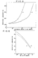
- Figure 9 shows the relation between the amount of the second activator and the relative luminance of the phosphor obtained.
- line a shows the relation between the amount of Cu (second activator) and the relative luminance of a ZnS:Ag, In, Cu, CI phosphor in which the amounts of Ag, In and Cl are 10 -2 %, 2 ⁇ 10 -3 % and 10 -4 %, respectively, and which has a main crystalline phase of a cubic system
- line b shows the relation between the amount of Au (second activator) and the relative luminance of a ZnS:Ag, In, Au, CI phosphor in which the amounts of Ag, Ga and CI are equal to the above values, and which has main crystalline phase of a cubic system.
- the luminance of ZnS:Ag, In, CI phosphor which is activated with the same amounts of Ag, In and Cl as the above values but is not activated with the second activator is defined to be 100%.
- the luminance of emission of the ZnS:Ag, In, CI phosphor is highly improved when further activated with Cu and/or Au.
- the amount of Cu and/or Au is excessive, the color purity is lowered, and the phosphor comes to emit white light. Therefore, the amount of Au and/or Cu should not be more than 2 ⁇ 10 -2 %.
- the particularly preferred range of the amount of Cu and Au are 5x 10 -5 to 8x 10 -4 % and 5x10- 4 to 8x10- 3 %, respectively.
- Figures 10 to 13 are graphs for illustrating the influence of sulfur on the luminance of emission of phosphors.
- line a shows the relation between the amount of Ga and the relative luminance of emission of ZnS:Ag, Ga, CI without sulfur in which the amounts Ag and CI are 10 -2 % and 10 -4 %, respectively
- line b shows the relation between the amount of Ga and the relative luminance of emission of a ZnS:Ag, Ga, CI phosphor which contains therein 10 -4 % sulfur and in which the amounts of Ag and CI are equal to those of the phosphor without sulfur.
- Both the phosphors with and without sulfur have a main crystalline phase of a cubic system.
- the luminance of emission is lowered as the amount of Ga is increased in either of phosphors with and without sulfur.
- the luminance of emission of the phosphor with sulfur is higher than the phosphor without sulfur. That is, the trace amount of sulfur suppresses the adverse influence of Ga on the luminance of emission.
- This effect of sulfur is particularly significant when the amount of sulfur is in the range of 5 ⁇ 10 -5 to 10 -3 %. Since sulfur hardly influences the afterglow, characteristics and the color purity, when taking into account the luminance of emission, the ZnS:Ag, Ga, Cl phosphors with sulfur is more suitable than those without sulfur for use in the high resolution cathode-ray tube.
- line a shows the relation between the amount of Ga and the relative luminance of emission of a ZnS:Ag, Ga, Cu, Cl without sulfur in which the amounts Ag, Cu and CI are 10 -2 %, 2 ⁇ 10 -4 % and 10 -4 %, respectively
- line b shows the relation between the amount of Ga and the relative luminance of emission of a ZnS:Ag, Ga, Cu, CI phosphor which contains therein 10 -4 % sulfur and in which the amounts of Ag, Cu and CI are equal to those of the phosphor without sulfur.
- Both the phosphors with and without sulfur have a main crystalline phase of a cubic system.
- the luminance of emission is lowered as the amount of Ga is increased in either of phosphors with and without sulfur.
- the luminance of emission of the phosphor with sulfur is higher than the phosphor without sulfur. That is, the trace amount of sulfur suppresses the adverse influence of Ga on the luminance of emission.
- This effect of sulfur is particularly significant when the amount of sulfur is in the range of 5 ⁇ 10 -5 to 10 -3 %. Since sulfur hardly influences the afterglow characteristics and the color purity, when taking into account the luminance of emission, the ZnS:Ag, Ga, Cl phosphors with sulfur is more suitable than those without sulfur for use in the high resolution cathode-ray tube.
- line a shows the relation between the amount of In and the relative luminance of emission of a ZnS:Ag, In, Cl without sulfur in which the amounts Ag and CI are 10 -2 % and 10 -4 %, respectively
- line b shows the relation between the amount of In and the relative luminance of emission of a ZnS:Ag, In, CI phosphor which contains therein 10 -4 % sulfur and in which the amounts of Ag and CI are equal to those of the phosphor without sulfur.
- Both the phosphors with and without sulfur have a main crystalline phase of a cubic system.
- the luminance of emission is lowered as the amount of In is increased in either of phosphors with and without sulfur.
- the luminance of emission of the phosphor with sulfur is higher than the phosphor without sulfur. That is, the trace amount of sulfur suppresses the adverse influence of Ga on the luminance of emission.
- This effect of sulfur is particularly significant when the amount of sulfur is in the range of 5x 10⁻⁵ to 10- 3 %. Since sulfur hardly influences the afterglow characteristics and the color purity, when taking into account the luminance of emission, the ZnS:Ag, Ga, CI phosphors with sulfur is more suitable than those without sulfur for use in the high resolution cathode-ray tube.
- line a shows the relation between the amount of In and the relative luminance of emission of a ZnS:Ag, In, Cu, CI without sulfur in which the amounts Ag, Cu and CI are 10 -2 %, 2 ⁇ 10 -4 % and 10 -4 %, respectively
- line b shows the relation between the amount of In and the relative luminance of emission of a ZnS:Ag, In, Cu, CI phosphor which contains therein 10- 4 % sulfur and in which the amounts of Ag, Cu and CI are equal to those of the phosphor without sulfur.
- Both the phosphors with and without sulfur have a main crystalline phase of a cubic system.
- the luminance of emission is lowered as the amount of In is increased in either of phosphors with and without sulfur.
- the luminance of emission of the phosphor with sulfur is higher than the phosphor without sulfur. That is, the trace amount of sulfur suppresses the adverse influence of In on the luminance of emission.
- This effect of sulfur is particularly significant when the amount of sulfur is in the range of 5x10- 5 to 10- 3 %. Since sulfur hardly influences the afterglow characteristics and the color purity, when taking into accountthe luminance of emission, the ZnS:Ag, In, Cu phosphors with sulfur is more suitable than those without sulfur for use in the high resolution cathode-ray tube.
- the electron excited fluorescent display device of the present invention is characterized in that its fluorescent screen has the long afterglow blue emitting phosphor of the present invention as the major component of the blue emitting component.
- high resolution cathode-ray tubes such as color cathode-ray tubes, black-and-white cathode-ray tubes and monochromatic display tube and low-velocity electron excited fluorescent display tubes are included.
- the blue emitting component phosphor of the fluorescent screen thereof includes at least one kind of the phosphors of the present invention as the major component.
- the afterglow time of the phosphor of the present invention changes in the range of 5 to 300 ms depending on the activating amount of the first co-activator (Ga and/or In) and the current density of the exciting electron beam. It has been found that when the afterglow time of the phosphors employed in the high resolution cathode-ray tube is not longer than 5 ms, flicker appears in an image on the screen, while when the afterglow time of the same is not shorter than 150 ms, after-images appear. Therefore, the afterglow time of the phosphors employed in the high resolution cathode-ray tube of the present invention should be in the range of 5 to 150 ms though depending on the current density of the exciting electron beam.
- the blue emitting component phosphor of the fluorescent screen of the high resolution cathode-ray tube of the present invention may solely consist of at least one kind of the phosphor of the present invention, or may consist of at least one kind of phosphors of the present invention and a short afterglow time blue emitting phosphor mixed therein in a proper mixing ratio to control the afterglow characteristics and/or the luminance of emission.
- the afterglow time of the phosphors of the present invention is 5 to 80 ms under excitation by an electron beam having the current density of 1 uA/cm 2.
- the afterglow time of the phosphors of the present invention can be extended up to about 300 ms by reducing the current density of the exciting electron beam.
- at least one kind of short afterglow blue emitting phosphor is mixed in the phosphor of the present invention in a proper mixing ratio to produce the blue emitting component phosphor the afterglow time of which is in the range of 5 to 150 ms.
- said conventional ZnS:Ag, X phosphors can be used as the shortglow time blue emitting phosphor to be mixed in the phosphor of the present invention.
- the blue emitting component phosphor of the fluorescent screen of the cathode-ray tube of the present invention there is hardly any possibility of occurrence of color drift after interruption of the excitation since it solely consists of the blue emitting phosphor of the present invention or of the phosphor of the present invention and short afterglow phosphor emitting light of color similar to the color of the light emitted from the phosphor of the present invention. Further the blue emitting component phosphor according to the present invention is free from color shading even if it is produced by mixing the short afterglow blue emitting phosphor in the phosphor of the present invention unlike the conventional light blue phosphor which is produced by mixing phosphors having different luminescent colors.
- the phosphors of the present invention emit blue light the color purity of which is significantly higher than that of the conventional light blue phosphor. Therefore, the blue emitting component phosphor including the long afterglow time blue emitting phosphor of the present invention at least as the major component thereof emits blue light the color purity of which is significantly higher than that of the conventional light blue phosphor.
- the afterglow time of the green emitting component phosphor forming the fluorescent screen of the cathode-ray tube of the present invention should also be in the range of 5 to 150 ms. Therefore, the green emitting component phosphor are used those the afterglow time of which is longer than 5 ms.
- the afterglow time of known ZnSi0 4 :Mn phosphors and known ZnSi0 4 :Mn, As phosphors is not shorter than 5 ms.
- the green emitting component phosphor may be produced by mixing short afterglow green emitting phosphor in long afterglow green emitting phosphor in a proper mixing ratio to produce the green emitting component phosphor having the afterglow time of 5 to 150 ms.
- the short afterglow time green emitting phosphor may be used known copper and aluminium activated zinc sulfide phosphor (ZnS:Cu, Al), copper, gold and aluminium activated zinc sulfide phosphor (ZnS:Cu, Au, Al), silver activated zinc cadmium sulfide phosphor [(Zn, Cd)S:Ag], copper activated zinc cadmium sulfide phosphor [(Zn, Cd)S:Cu], copper and chroline activated zinc sulfide phosphor (ZnS:Cu, CI), copper and aluminium activated zinc cadmium sulfide phosphor [(Zn, Cd):Cu, Al], silver and aluminium activated zinc cadmium sulfide phosphor [(Zn, Cd)S:Ag, AI], and terbium activated rare earth oxysulfide phosphore (Ln 2 0 2 S:Tb wherein Ln is at least one
- the afterglow time of the red emitting component phosphor forming the fluorescent screen of the cathode-ray tube of the present invention should also be in the range of 5 to 150 ms. Therefore, the red emitting component phosphor is formed of orange to red emitting phosphors the afterglow time of which is longer than 5 ms.
- the red emitting component phosphor may be produced by mixing short afterglow orange to red emitting phosphor in long afterglow orange to red emitting phosphor in a proper mixing ratio to produce the red emitting component phosphor having the afterglow time of 5 to 150 ms.
- the short afterglow time orange to red phosphor may be used europium activated rare earth oxysulfide phosphors (Ln 2 0 2 S:Eu, wherein Ln has the same significance as described above), europium activated rare earth vanadate phosphors (LnV0 4 :Eu wherein Ln has the same significance as defined above), gold and aluminium activated zinc sulfide phosphors and the like.
- black-and-white type high resolution cathode-ray tube its fluorescent screen is formed of a layer of white emitting phosphor which is obtained by mixing the blue, red and green emitting component phosphors with each other in a proper mixing ratio.
- the mixed phosphor may be applied to the surface of a face plate using various methods commonly and widely used in making fluorescent screens, e.g., sedimentation method, or rotary coating method.
- a layer of metal (metal back) such as 'aluminium is deposited on the rear face (the incident face of the electron beam) in order to prevent charge-up upon excitation.
- the mechanical arrangement of the black-and-white cathode-ray tube of the present invention is the same as that of conventional one. Therefore, it will not be described in detail here.
- the blue emitting component phosphor employed in the fluorescent screen of the high resolution cathode-ray tube of the present invention exhibits sufficiently long afterglow time and is substantially free from color drift after interruption of the excitation. Therefore, the fluorescent screen emits white light even after the interruption of the excitation unlike the conventional fluorescent screen using the light blue phosphor as the blue emitting component phosphor.
- the high resolution cathode-ray tube of the present invention is in the form of a color cathode-ray tube
- its fluorescent screen is formed of a plurality of regularly arranged light emitting element trios, each trio being formed of a blue light emitting element, a green light emitting element and red light emitting element.
- Each light emitting element is in the form of a dot or a stripe as in the conventional color cathode-ray tube.
- each element is in the form of a dot.
- the light emitting elements are formed on the face plate using a known method such as optical printing.
- a metal back is provided on the rear face of the fluorescent screen as in the fluorescent screen of the black-and-white cathode-ray tube.
- a shadow mask is generally provided between the fluorescent screen and electron guns which is generally three in number.
- the mechanical arrangement of the high resolution color cathode-ray tube of the present invention is the same as that of known one. Therefore, it will not be described in detail.
- the color of light emitted from the fluorescent screen of the high resolution color cathode-ray tube of the present invention after interruption of excitation does not differ from that of during excitation unlike the fluorescent screen using the known light blue phosphor.
- a part of the first co-activator may be replaced by scandium.
- Phosphors activated with scandium instead of Ga and/or In as the ' first co-activator exhibit slightly extended afterglow time.
- extension of the afterglow time obtained by scandium is much less than the same obtained by Ga and/or In.
- the phosphors of the present invention may be further activated with divalent europium, bismuth, antimony and the like.
- the above raw materials were mixed well with each other by means of a ball mill and then a proper amount of sulfur and carbon were added thereto.
- the mixture obtained was placed in a quartz crucible and fired for 3 hours at 950°C in an electric furnace with the lid of the crucible being covered. This firing was performed in a carbon disulfide atmosphere in the crucible. After firing, the fired product was washed with water, dried and sieved to provide a ZnS:Ag, Ga, Cl phosphor in which the activating amounts of Ag, Ga and CI were 10 -2 %, 10 -2 % and 10 -4 %, respectively.
- the obtained phosphor emitted blue light having high color purity under excitation by an electron beam and the 10% afterglow time of the phosphor was about 35 ms.
- the obtained phosphor emitted blue light having high color purity under excitation by an electron beam and the 10% afterglow time of the phosphor was about 18 ms.
- the obtained phosphor emitted blue light having high color purity under excitation by an electron beam and the 100% afterglow time of the phosphor was about 55 ms.
- the obtained phosphor emitted blue light having high color purity under excitation by an electron beam and the 10% afterglow time of the phosphor was about 12 ms.
- the obtained phosphor emitted blue light having high color purity under excitation by an electron beam and the 10% afterglow time of the phosphor was about 14 ms.
- the obtained phosphor emitted blue light under excitation by an electron beam and the emission spectrum thereof was as shown by the line b in Figure 6. Further, the 10% afterglow time of the phosphor was about 40 ms. Further, the luminance of emission of the phosphor was 50% higher than that of the ZnS:Ag, Ga, CI phosphor activated with the same amount of Ag, Ga and Cl as the phosphor obtained.
- a ZnS:Ag, Ga, Au, CI phosphor in which the activating amounts of Ag, Ga, Au and CI were 10 -2 %, 10 -2 %, 2 ⁇ 10 -3 % and 10 -4 %, respectively, was obtained in the same manner as described in Example 10 except that 0.084 g of HAuCl 4 ⁇ 4H 2 0 was used instead of copper sulfate.
- the obtained phosphor emitted blue light having high color intensity under excitation by an electron beam and the emission spectrum thereof was as shown by the line c in Figure 6. Further, the 10% afterglow time of the phosphor was about 40 ms.
- the luminance of emission of the phosphor was 80% higher than that of the ZnS:Ag, Ga, CI phosphor activated with the same amount of Ag, Ga and CI as the phosphor obtained.
- Ammonium sulfide was added to aqueous zinc sulfate solution maintaining the pH value thereof at 5 to precipitate zinc sulfide.
- the zinc sulfide thus obtained included 7% by of sulfur in excess of stoichiometric amount on the basis of the weight of the zinc sulfide.
- the obtained phosphor emitted blue light having high color intensity under excitation by an electron beam and the emission spectrum thereof was as shown by the line b in Figure 6. Further, the 10% afterglow time of the phosphor was about 40 ms.
- the luminance of emission of the phosphor was 61 % higher than that of the ZnS:Ag, Ga, CI phosphor without sulfur activated with the same amount of Ag, Ga and CI as the phosphor obtained.
- the luminance of emission of the phosphor was 92% higher than that of ZnS:Ag, Ga, CI phosphor without sulfur activated with the same amount of Ag, Ga and Cl as the phosphor obtained.
- the obtained phosphor emitted blue light under excitation by an electron beam and the emission spectrum of the phosphor was as shown by the line b in Figure 7. Further, the 10% afterglow time of the phosphor was about 55 ms.
- the luminance of emission of the phosphor was 50% higher than that of ZnS:Ag, In, CI phosphor which was activated with the same amount of Ag, In and Cl as the phosphor obtained.
- the luminance of emission of the phosphor was 50% higher than that of ZnS:Ag, In, CI phosphor which was activated with the same amount of Ag, In, and CI as the phosphor obtained.
- the luminance of emission of the phosphor was 35% higher than that of ZnS:Ag, In, CI phosphor activated with the same amount of Ag, In and CI as the phosphor obtained.
- a ZnS:Ag, In, Au, CI phosphor in which the amounts of Ag, In, Au and CI were 10 -2 %, 10 -2 %, 2 ⁇ 10 -3 % and 10 -4 %, respectively, was obtained in the same manner as described in Example 17 except that 0.084 g of HAuCl 4 ⁇ 4H 2 0 was used instead of copper sulfate.
- the obtained phosphor emitted blue light under excitation by an electron beam and the emission spectrum of the phosphor was as shown by the line c in Figure 7. Further, the 10% afterglow time of the phosphor was about 55 ms.
- the luminance of emission of the phosphor was 80% higher than that of ZnS:Ag, In, CI phosphor activated with the same amount of Ag, In and CI as the phosphor obtained.
- the luminance of emission of the phosphor was 80% higher than that of ZnS:Ag, In, Cl phosphor activated with the same amount of Ag, In and Cl as the phosphor obtained.
- the obtained phosphor emitted blue light under excitation by an electron beam and the emission spectrum of the phosphor was substantially as shown by the line b in Figure 7. Further, the 10% afterglow time of the phosphor was about 55 ms. Further, the luminance of emission of the phosphor was 61% higher than that of a ZnS:Ag, In, CI phosphor without sulfur activated with the same amounts of Ag, In and CI as the phosphor.
- the luminance of emission of the phosphor was 92% higher than that of ZnS:Ag, In, CI phosphor without sulfur activated with the same amount of Ag, In and CI as the phosphor obtained.
- the obtained phosphor emitted blue light under excitation by an electron beam and the emission spectrum of the phosphor was substantially as shown by the line b in Figure 1. Further, the 10% afterglow time of the phosphor was about 40 ms.
- the obtained phosphor emitted blue light under excitation by an electron beam and the emission spectrum of the phosphor was as shown by the line d in Figure 1. Further, the 10% afterglow time of the phosphor was about 18 ms.
- the obtained phosphor emitted blue light under excitation by an electron beam and the emission spectrum of the phosphor was substantially as shown by the line b in Figure 2. Further, the 10% afterglow time of the phosphor was about 55 ms.
- the obtained phosphor emitted blue light under excitation by an electron beam and the emission spectrum of the phosphor was substantially as shown by the line d in Figure 2. Further, the 10% afterglow time of the phosphor was about 50 ms.
- Blue, green and red emitting component phosphors having the following characteristics were uniformly mixed in the following mixing ratio to produce a white emitting mixed phosphor.
- the mixed phosphor was evenly applied to a face plate using the known sedimentation coating method to make a fluorescent screen. Then a black-and-white cathode-ray tube in accordance with an embodiment of the present invention was produced according to a known method commonly used in the production of black-and-white cathode-ray tubes.
- a conventional black-and-white cathode-ray tube was produced in the same manner except that a short afterglow emitting ZnS:Ag, CI phosphor in which the main crystalline phase was of a cubic system and the activating amounts of Ag and CI were equal to those of said ZnS:Ag, Ga, CI phosphor was used instead of it.
- the fluorescent screen of the cathode-ray tube obtained was provided with a fluorescent layer including a light blue emitting phosphor obtained by mixing the ZnS:Ag, CI phosphor, said Zn 2 SiO 4 :Mn, As phosphor and said (Zn, Mg) 3 (PO 4 ) 2 :Mn phosphor as the blue emitting component phosphor.
- both the screens of the cathode-ray tube of the present invention and the conventional cathode-ray tube emitted white light the spectrum of which was as shown by the line a in Figure 14.
- the fluorescent screen of the conventional cathode-ray tube emitted yellow-green light 15 ms after interruption of excitation, and yellow light 30 ms after the interruption
- the screen of the cathode-ray tube of the present invention emitted light of substantially white in color both 15 ms and 30 ms after interruption of excitation.
- the lines b and c in Figure 14 show the emission spectra of the screen according to the present invention 15 ms and 30 ms after interruption of excitation, respectively.
- the line d and e in Figure 14 show the emission spectra of the screen of the conventional cathode-ray tube 15 ms and 30 ms after interruption of excitation, respectively.
- the light emitted from the screen of the cathode-ray tube of the present invention still includes the blue component until a lapse of 30 ms after interruption of excitation, while the light emitted from the screen of the conventional cathode-ray tube has lost the blue component before a lapse of 15 ms after interruption of excitation.
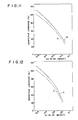
- Figure 15 is a CIE chromaticity graph showing chromaticity points of emission of the screens of the cathode-ray tube of thee present invention and the conventional cathode-ray tube under excitation by an electron beam, 15 ms after interruption of the excitation and 30 ms after interruption of the same. Further, the chromaticity point of emission of each phosphor forming the screens is also shown in Figure 15.
- the point A indicates the chromaticity of the long afterglow ZnS:Ag, Ga, CI phosphor forming the screen of the cathode-ray tube of the present invention orthe short afterglow ZnS:Ag, CI phosphor forming the screen of the conventional cathode-ray tube.
- the points B and C indicate the chromaticity of the Zn 2 SiO 4 :Mn, As phosphor and the same of the (Zn, Mg) 3 (P0 4 ) 2 :Mn phosphor, respectively which are common to both the cathode-ray tube.
- the chromaticity point of emission of the screen of the conventional cathode-ray moved 15 ms after interruption of excitation to the point G (corresponding to the line d in Figure 14) which was in yellow-green region, and then further moved 30 ms after interruption of excitation to the point H (corresponding to the line e in Figure 14) which was in yellow region.
- the color drift after interruption of excitation in the screen of the conventional cathode-ray tube is significant.
- a black-and-white cathode-ray tube was produced in the same manner as described in Example 32 except that the fluorescent screen was formed of the blue, green and red component phosphors having the following characteristics and mixed with each other in the following ratio.
- the screen of the obtained cathode-ray tube emitted white light under excitation by an electron beam and the chromaticity point of emission thereof did not change before or upon a lapse of 15 ms after interruption of the excitation.
- a black-and-white cathode-ray tube was produced in the same manner as described in Example 32 except that the fluorescent screen was formed of the blue, green and red component phosphors having the following characteristics and mixed with each other in the following ratio.
- the screen of the obtained cathode-ray tube emitted white light having the same chromaticity point as that of the light emitted from the screen of Example 33 under excitation by an electron beam, and the chromaticity point hardly changed before or upon a lapse of 15 ms after interruption of the excitation.
- a black-and-white cathode-ray tube was produced in the same manner as described in Example 32 except that as the blue component phosphor was used aZnS:Ag, In, CI phosphor which was activated with 10- 2 % Ag, 2x10- 3 % In and 10- 4 % Cl, and the afterglow time of which was 30 ms.
- the main crystalline phase of the above phosphor was of a cubic system.
- the lines d and e in Figure 16 show the emission spectra of the screen of the conventional cathode-ray tube 15 ms and 30 ms after interruption of excitation, respectively.
- the light emitted from the screen of the cathode-ray tube of the present invention still includes the blue component until a lapse of 30 ms after interruption of excitation, while the light emitted from the screen of the conventional cathode-ray tube has lost the blue component before a lapse of 15 ms after interruption of excitation.
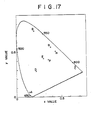
- Figure 17 is a CIE chromaticity graph showing chromaticity points of emission of the screens of the cathode-ray tube of the present invention and the conventional cathode-ray tube under excitation by an electron beam, 15 ms after interruption of the excitation and 30 ms after interruption of the same. Further, the chromaticity point of emission of each phosphor forming the screens is also shown in Figure 17.
- the point A indicates the chromaticity of the long afterglow ZnS:Ag, In, CI phosphor forming the screen of the cathode-ray tube of the present invention or the short afterglow ZnS:Ag, CI phosphor forming the screen of the conventional cathode-ray tube.
- the points B and C indicate the chromaticity of the Zn 2 SiO 4 :Mn, As phosphor and the same of the (Zn, Mg) 3 (P0 4 ) 2 :Mn phosphor, respectively, which are common to both the cathode-ray tube.
- the chromaticity point of emission of the screen of the conventional cathode-ray moved 15 ms after interruption of excitation to the point G (corresponding to the line d in Figure 16) which was in yellow-green region, and then further moved 31 ms after interruption of excitation to the point H (corresponding to the line e in Figure 16) which was in yellow region.
- the color drift after interruption of excitation in the screen of the conventional cathode-ray tube is significant.
- a black-and-white cathode-ray tube was produced in the same manner as described in Example 32 except that the fluorescent screen was formed of the blue, green and red component phosphors having the following characteristics and mixed with each other in the following ratio.
- the screen of the obtained cathode-ray tube emitted white light under excitation by an electron beam and the chromaticity point of emission thereof did not change before or upon a lapse of 15 ms after interruption of the excitation.
- a black-and-white cathode-ray tube was produced in the same manner as described in Example 32 except that the fluorescent screen was formed of the blue, green and red component phosphors having the following characteristics and mixed with each other in the following ratio.
- the screen of the obtained cathode-ray tube emitted white light having the same chromaticity point as that of the light emitted from the screen of Example 39 under excitation by an electron beam, and the chromaticity point hardly changed before or upon a lapse of 15 ms after interruption of the excitation.
- a black-and-white cathode-ray tube was produced in the same manner as described in Example 32 except that the fluorescent screen was formed of the blue, green and red component phosphors having the following characteristics and mixed with each other in- the following ratio.
- the screen of the obtained cathode-ray tube emitted white light having the same chromaticity point as that of the light emitted from the screen of Example 39 under excitation by an electron beam, and the chromaticity point hardly changed before or upon a lapse of 15 ms after interruption of the excitation.
- a black-and-white cathode-ray tube was produced in the same manner as described in Example 32 except that the fluorescent screen was formed of the blue, green and red component phosphors having the following characteristics and mixed with each other in the following ratio.
- the screen of the obtained cathode-ray tube emitted white light having the same chromaticity point as that of the light emitted from the screen of Example 39 under excitation by an electron beam, and the chromaticity point hardly changed before or upon a lapse of 15 ms after interruption of the excitation.
Landscapes
- Chemical & Material Sciences (AREA)
- Inorganic Chemistry (AREA)
- Engineering & Computer Science (AREA)
- Materials Engineering (AREA)
- Organic Chemistry (AREA)
- Luminescent Compositions (AREA)
Claims (16)
Applications Claiming Priority (16)
| Application Number | Priority Date | Filing Date | Title |
|---|---|---|---|
| JP17617081A JPS5879814A (ja) | 1981-11-02 | 1981-11-02 | 硫化亜鉛螢光体 |
| JP176170/81 | 1981-11-02 | ||
| JP18072181A JPS5883085A (ja) | 1981-11-11 | 1981-11-11 | 硫化亜鉛螢光体 |
| JP180721/81 | 1981-11-11 | ||
| JP18162481A JPS5883084A (ja) | 1981-11-12 | 1981-11-12 | 硫化亜鉛螢光体 |
| JP181624/81 | 1981-11-12 | ||
| JP193247/81 | 1981-12-01 | ||
| JP19324781A JPS5893780A (ja) | 1981-12-01 | 1981-12-01 | 高解像度陰極線管 |
| JP21227881A JPS58115024A (ja) | 1981-12-29 | 1981-12-29 | 硫化亜鉛螢光体 |
| JP212278/81 | 1981-12-29 | ||
| JP113382A JPS58120521A (ja) | 1982-01-07 | 1982-01-07 | 硫化亜鉛螢光体 |
| JP1133/82 | 1982-01-07 | ||
| JP1286682A JPS58129083A (ja) | 1982-01-29 | 1982-01-29 | 硫化亜鉛螢光体 |
| JP12867/82 | 1982-01-29 | ||
| JP1286782A JPS58129084A (ja) | 1982-01-29 | 1982-01-29 | 高解像度陰極線管 |
| JP12866/82 | 1982-01-29 |
Publications (2)
| Publication Number | Publication Date |
|---|---|
| EP0078538A1 EP0078538A1 (de) | 1983-05-11 |
| EP0078538B1 true EP0078538B1 (de) | 1986-03-12 |
Family
ID=27571426
Family Applications (1)
| Application Number | Title | Priority Date | Filing Date |
|---|---|---|---|
| EP82110097A Expired EP0078538B1 (de) | 1981-11-02 | 1982-11-02 | Blau-emittierender Leuchtstoff mit langer Nachleuchtzeit und eine denselben verwendende, durch Elektronen angeregte Anzeigevorrichtung |
Country Status (3)
| Country | Link |
|---|---|
| EP (1) | EP0078538B1 (de) |
| KR (1) | KR910001399B1 (de) |
| DE (2) | DE78538T1 (de) |
Families Citing this family (3)
| Publication number | Priority date | Publication date | Assignee | Title |
|---|---|---|---|---|
| TW567222B (en) | 2000-04-11 | 2003-12-21 | Toshiba Corp | Phosphor for display and field-emission display |
| KR100417079B1 (ko) * | 2001-05-08 | 2004-02-05 | 주식회사 엘지화학 | 형광체용 단결정 황화아연 분말의 제조방법 |
| KR100496288B1 (ko) * | 2002-11-27 | 2005-06-17 | 삼성에스디아이 주식회사 | 황화아연계 모체로 구현한 황색 발광 형광체 및 그의제조방법 |
Family Cites Families (5)
| Publication number | Priority date | Publication date | Assignee | Title |
|---|---|---|---|---|
| US2915661A (en) * | 1953-02-19 | 1959-12-01 | Westinghouse Electric Corp | Color television screen |
| US2947704A (en) * | 1957-04-10 | 1960-08-02 | Gen Electric | Luminescent zinc sulfide phosphors and the preparation thereof |
| GB1153754A (en) * | 1965-06-16 | 1969-05-29 | Sylvania Electric Prod | Cathodoluminescent Screens |
| US3507805A (en) * | 1967-04-18 | 1970-04-21 | Westinghouse Electric Corp | Long-afterglow phosphor |
| JPS569945A (en) * | 1979-07-04 | 1981-01-31 | Matsushita Electronics Corp | Cathode-ray tube |
-
1982
- 1982-11-01 KR KR828204919A patent/KR910001399B1/ko active
- 1982-11-02 DE DE198282110097T patent/DE78538T1/de active Pending
- 1982-11-02 EP EP82110097A patent/EP0078538B1/de not_active Expired
- 1982-11-02 DE DE8282110097T patent/DE3269876D1/de not_active Expired
Also Published As
| Publication number | Publication date |
|---|---|
| EP0078538A1 (de) | 1983-05-11 |
| DE3269876D1 (en) | 1986-04-17 |
| KR910001399B1 (ko) | 1991-03-04 |
| KR840002581A (ko) | 1984-07-02 |
| DE78538T1 (de) | 1983-11-10 |
Similar Documents
| Publication | Publication Date | Title |
|---|---|---|
| EP0091184B1 (de) | Phosphore und ihre Anwendung in durch Elektronen angeregten Fluoreszenz-Anzeigevorrichtungen | |
| EP0123947B1 (de) | Zinksilikat-Phosphor und Elektronen angeregte fluoreszierende Anzeigevorrichtung mit diesem Phosphor | |
| US5277841A (en) | Mixed blue emitting phosphor | |
| EP0087476B1 (de) | Aufzeichnungsvorrichtung | |
| US5231328A (en) | Phosphor and ultraviolet ray excited fluorescent tube employing it | |
| EP0078538B1 (de) | Blau-emittierender Leuchtstoff mit langer Nachleuchtzeit und eine denselben verwendende, durch Elektronen angeregte Anzeigevorrichtung | |
| JP2856895B2 (ja) | 顔料付き緑色発光蛍光体 | |
| KR860001896B1 (ko) | 규산아연 형광체 | |
| JPH06103915A (ja) | カラー陰極線管 | |
| JPH06100860A (ja) | 青色発光蛍光体 | |
| JPH0456073B2 (de) | ||
| JPH072945B2 (ja) | 残光性硫化亜鉛蛍光体 | |
| KR100342648B1 (ko) | 새로운적색형광체 | |
| JPS6144911B2 (de) | ||
| EP0296531B1 (de) | Phosphor, Verfahren zur Herstellung desselben und denselben verwendendes, mit Ultraviolettstrahlen aktiviertes Leuchtstoffrohr | |
| JPH0129834B2 (de) | ||
| JPH072946B2 (ja) | 螢光体 | |
| JPS6332111B2 (de) | ||
| JPH0629420B2 (ja) | 蛍光体 | |
| JPH058235B2 (de) | ||
| JPH07116430B2 (ja) | 長残光性青色発光混合物螢光体 | |
| JPH01189A (ja) | 螢光体 | |
| JP3232539B2 (ja) | モノクロcrt用希土類蛍光体 | |
| JPS6144910B2 (de) | ||
| JPH0258308B2 (de) |
Legal Events
| Date | Code | Title | Description |
|---|---|---|---|
| PUAI | Public reference made under article 153(3) epc to a published international application that has entered the european phase |
Free format text: ORIGINAL CODE: 0009012 |
|
| AK | Designated contracting states |
Designated state(s): DE GB NL |
|
| TCNL | Nl: translation of patent claims filed | ||
| DET | De: translation of patent claims | ||
| 17P | Request for examination filed |
Effective date: 19831108 |
|
| GRAA | (expected) grant |
Free format text: ORIGINAL CODE: 0009210 |
|
| AK | Designated contracting states |
Kind code of ref document: B1 Designated state(s): DE GB NL |
|
| REF | Corresponds to: |
Ref document number: 3269876 Country of ref document: DE Date of ref document: 19860417 |
|
| NLR4 | Nl: receipt of corrected translation in the netherlands language at the initiative of the proprietor of the patent | ||
| PLBE | No opposition filed within time limit |
Free format text: ORIGINAL CODE: 0009261 |
|
| STAA | Information on the status of an ep patent application or granted ep patent |
Free format text: STATUS: NO OPPOSITION FILED WITHIN TIME LIMIT |
|
| 26N | No opposition filed | ||
| PGFP | Annual fee paid to national office [announced via postgrant information from national office to epo] |
Ref country code: NL Payment date: 19980916 Year of fee payment: 17 |
|
| PGFP | Annual fee paid to national office [announced via postgrant information from national office to epo] |
Ref country code: GB Payment date: 19980930 Year of fee payment: 17 |
|
| PGFP | Annual fee paid to national office [announced via postgrant information from national office to epo] |
Ref country code: DE Payment date: 19981231 Year of fee payment: 17 |
|
| PG25 | Lapsed in a contracting state [announced via postgrant information from national office to epo] |
Ref country code: GB Free format text: LAPSE BECAUSE OF NON-PAYMENT OF DUE FEES Effective date: 19991102 |
|
| PG25 | Lapsed in a contracting state [announced via postgrant information from national office to epo] |
Ref country code: NL Free format text: LAPSE BECAUSE OF NON-PAYMENT OF DUE FEES Effective date: 20000601 |
|
| GBPC | Gb: european patent ceased through non-payment of renewal fee |
Effective date: 19991102 |
|
| NLV4 | Nl: lapsed or anulled due to non-payment of the annual fee |
Effective date: 20000601 |
|
| PG25 | Lapsed in a contracting state [announced via postgrant information from national office to epo] |
Ref country code: DE Free format text: LAPSE BECAUSE OF NON-PAYMENT OF DUE FEES Effective date: 20000901 |