EP0052865A2 - Verstärkung für die Zentrieröffnung einer Floppy-Disk - Google Patents
Verstärkung für die Zentrieröffnung einer Floppy-Disk Download PDFInfo
- Publication number
- EP0052865A2 EP0052865A2 EP81109776A EP81109776A EP0052865A2 EP 0052865 A2 EP0052865 A2 EP 0052865A2 EP 81109776 A EP81109776 A EP 81109776A EP 81109776 A EP81109776 A EP 81109776A EP 0052865 A2 EP0052865 A2 EP 0052865A2
- Authority
- EP
- European Patent Office
- Prior art keywords
- recording disk
- flexible recording
- liquid
- central aperture
- disk
- Prior art date
- Legal status (The legal status is an assumption and is not a legal conclusion. Google has not performed a legal analysis and makes no representation as to the accuracy of the status listed.)
- Granted
Links
- 230000002787 reinforcement Effects 0.000 title claims abstract description 48
- 239000007788 liquid Substances 0.000 claims abstract description 44
- 239000000463 material Substances 0.000 claims abstract description 32
- 238000000034 method Methods 0.000 claims abstract description 21
- 239000000178 monomer Substances 0.000 claims abstract description 11
- 229920000098 polyolefin Polymers 0.000 claims abstract description 10
- 239000003431 cross linking reagent Substances 0.000 claims abstract description 4
- 239000002904 solvent Substances 0.000 claims abstract description 3
- 230000003014 reinforcing effect Effects 0.000 claims description 14
- 239000011248 coating agent Substances 0.000 claims description 8
- 238000000576 coating method Methods 0.000 claims description 8
- 230000005855 radiation Effects 0.000 claims description 6
- 230000006872 improvement Effects 0.000 claims description 3
- 238000007872 degassing Methods 0.000 claims 1
- 238000009877 rendering Methods 0.000 claims 1
- 238000010023 transfer printing Methods 0.000 abstract description 4
- 229920001971 elastomer Polymers 0.000 abstract description 3
- 239000007787 solid Substances 0.000 abstract description 2
- 239000011344 liquid material Substances 0.000 abstract 1
- 230000008901 benefit Effects 0.000 description 8
- 230000000712 assembly Effects 0.000 description 6
- 238000000429 assembly Methods 0.000 description 6
- 239000000853 adhesive Substances 0.000 description 3
- 230000001070 adhesive effect Effects 0.000 description 3
- 239000010410 layer Substances 0.000 description 3
- 239000000203 mixture Substances 0.000 description 3
- 230000008569 process Effects 0.000 description 3
- OKTJSMMVPCPJKN-UHFFFAOYSA-N Carbon Chemical compound [C] OKTJSMMVPCPJKN-UHFFFAOYSA-N 0.000 description 2
- 230000004075 alteration Effects 0.000 description 2
- 238000005266 casting Methods 0.000 description 2
- 238000013500 data storage Methods 0.000 description 2
- 238000004519 manufacturing process Methods 0.000 description 2
- 238000012986 modification Methods 0.000 description 2
- 230000004048 modification Effects 0.000 description 2
- 239000002245 particle Substances 0.000 description 2
- 229920002379 silicone rubber Polymers 0.000 description 2
- 238000007711 solidification Methods 0.000 description 2
- 230000008023 solidification Effects 0.000 description 2
- CJYDNDLQIIGSTH-UHFFFAOYSA-N 1-(3,5,7-trinitro-1,3,5,7-tetrazocan-1-yl)ethanone Chemical compound CC(=O)N1CN([N+]([O-])=O)CN([N+]([O-])=O)CN([N+]([O-])=O)C1 CJYDNDLQIIGSTH-UHFFFAOYSA-N 0.000 description 1
- 239000004944 Liquid Silicone Rubber Substances 0.000 description 1
- 238000004026 adhesive bonding Methods 0.000 description 1
- 239000012790 adhesive layer Substances 0.000 description 1
- 230000002411 adverse Effects 0.000 description 1
- 239000002216 antistatic agent Substances 0.000 description 1
- 239000003849 aromatic solvent Substances 0.000 description 1
- 239000011230 binding agent Substances 0.000 description 1
- 229910052799 carbon Inorganic materials 0.000 description 1
- 125000004432 carbon atom Chemical group C* 0.000 description 1
- 230000008859 change Effects 0.000 description 1
- 239000003638 chemical reducing agent Substances 0.000 description 1
- 239000003795 chemical substances by application Substances 0.000 description 1
- 238000011109 contamination Methods 0.000 description 1
- 230000001351 cycling effect Effects 0.000 description 1
- 230000002950 deficient Effects 0.000 description 1
- 230000000694 effects Effects 0.000 description 1
- 238000009472 formulation Methods 0.000 description 1
- 239000007789 gas Substances 0.000 description 1
- 229910002804 graphite Inorganic materials 0.000 description 1
- 239000010439 graphite Substances 0.000 description 1
- 229930195733 hydrocarbon Natural products 0.000 description 1
- 150000002430 hydrocarbons Chemical class 0.000 description 1
- 238000003780 insertion Methods 0.000 description 1
- 230000037431 insertion Effects 0.000 description 1
- 150000002646 long chain fatty acid esters Chemical class 0.000 description 1
- 150000004668 long chain fatty acids Chemical class 0.000 description 1
- 230000007774 longterm Effects 0.000 description 1
- 239000000314 lubricant Substances 0.000 description 1
- 239000000696 magnetic material Substances 0.000 description 1
- 239000006249 magnetic particle Substances 0.000 description 1
- 230000007246 mechanism Effects 0.000 description 1
- 229910052751 metal Inorganic materials 0.000 description 1
- 239000002184 metal Substances 0.000 description 1
- 150000002739 metals Chemical class 0.000 description 1
- 230000010355 oscillation Effects 0.000 description 1
- 150000002978 peroxides Chemical class 0.000 description 1
- 229920000728 polyester Polymers 0.000 description 1
- 238000006116 polymerization reaction Methods 0.000 description 1
- 238000002360 preparation method Methods 0.000 description 1
- 230000009467 reduction Effects 0.000 description 1
- 239000004945 silicone rubber Substances 0.000 description 1
- 239000012748 slip agent Substances 0.000 description 1
- 239000011343 solid material Substances 0.000 description 1
- 230000003068 static effect Effects 0.000 description 1
- 238000003860 storage Methods 0.000 description 1
- 239000004094 surface-active agent Substances 0.000 description 1
- 230000002463 transducing effect Effects 0.000 description 1
Images

Classifications
-
- G—PHYSICS
- G11—INFORMATION STORAGE
- G11B—INFORMATION STORAGE BASED ON RELATIVE MOVEMENT BETWEEN RECORD CARRIER AND TRANSDUCER
- G11B17/00—Guiding record carriers not specifically of filamentary or web form, or of supports therefor
-
- G—PHYSICS
- G11—INFORMATION STORAGE
- G11B—INFORMATION STORAGE BASED ON RELATIVE MOVEMENT BETWEEN RECORD CARRIER AND TRANSDUCER
- G11B23/00—Record carriers not specific to the method of recording or reproducing; Accessories, e.g. containers, specially adapted for co-operation with the recording or reproducing apparatus ; Intermediate mediums; Apparatus or processes specially adapted for their manufacture
- G11B23/0014—Record carriers not specific to the method of recording or reproducing; Accessories, e.g. containers, specially adapted for co-operation with the recording or reproducing apparatus ; Intermediate mediums; Apparatus or processes specially adapted for their manufacture record carriers not specifically of filamentary or web form
- G11B23/0021—Record carriers not specific to the method of recording or reproducing; Accessories, e.g. containers, specially adapted for co-operation with the recording or reproducing apparatus ; Intermediate mediums; Apparatus or processes specially adapted for their manufacture record carriers not specifically of filamentary or web form discs
- G11B23/0028—Details
- G11B23/0035—Details means incorporated in the disc, e.g. hub, to enable its guiding, loading or driving
-
- G—PHYSICS
- G11—INFORMATION STORAGE
- G11B—INFORMATION STORAGE BASED ON RELATIVE MOVEMENT BETWEEN RECORD CARRIER AND TRANSDUCER
- G11B23/00—Record carriers not specific to the method of recording or reproducing; Accessories, e.g. containers, specially adapted for co-operation with the recording or reproducing apparatus ; Intermediate mediums; Apparatus or processes specially adapted for their manufacture
- G11B23/02—Containers; Storing means both adapted to cooperate with the recording or reproducing means
- G11B23/03—Containers for flat record carriers
- G11B23/033—Containers for flat record carriers for flexible discs
- G11B23/0332—Containers for flat record carriers for flexible discs for single discs, e.g. envelopes
Definitions
- This invention relates to the field of magnetic recording and more particularly to an improved floppy disk of the type used in digital data storage units and a method of manufacturing the same.
- floppy disks Widely used in the computer industry is a removable and interchangeable data storage medium assembled by enclosing a circular disk of flexible material coated with magnetic particles within an envelope. These assemblies are known in the trade as "floppy disks.” A method of constructing floppy disk assemblies is described in U.S. Patent 3,668,658 issued to Flores, et al. Both the envelope end the flexible recording disk contained therein, as described in that patent, are formed with a circular aperture passing through their respective centres. In accordance with that patent, the diameter of the circular aperture formed through the envelope is larger than that formed through the flexible recording disk. A larger aperture is formed in the envelope to permit engagement of the recording disk contained therein by a drive spindle of an apparatus used to write data to and read data from the flexible disk.
- Such misalignment which causes the centre of previously written data tracks to be displaced from the centre of rotation of the spindle, may cause the data stored thereon to be unreadable due to excessive oscillation of the data track with respect to the reading apparatus. This type of failure may sometimes be apparently cured by merely again dismounting and remounting the floppy disk assembly.
- a means for reducing this damage includes mechanically reinforcing the region of the flexible recording disk immediately surrounding the central aperture.
- One such reinforcement structure is described in U.S. Patent 4,052,750 issued to Barber, et al. The structure and method described there, consists of adhesively bonding a punched annular-shaped piece of structural material to the surface of the flexible recording disk about its central aperture. That patent further describes that the reinforcement, so applied, must have certain frictional properties to permit proper mechanical engagement by the reading and writing apparatus and certain electrical properties to allow dissipation of static electrical charges which may build up on the flexible recording disk.
- An object of the present invention is to provide an improved reinforcement about the central aperture of a flexible recording disk.
- Another object is to provide a reinforcement about the central aperture of a flexible recording disk which will not ultimately project thereinto and thereby contaminate reading and writing apparatus upon which it is mounted.
- Another object is to provide a reinforcement member for the central aperture of a flexible recording disk having improved mechanical properties.
- Another object is to provide a reinforcement member for the central aperture of a flexible recording disk having more uniform electrical properties.
- Another object is to provide a reinforcement member for the central aperture of a flexible recording disk which facilitates engagement of that aperture by a spindle of a reading and writing apparatus.
- Another object is to provide a lower cost and simpler method of reinforcing the central aperture of a flexible recording disk.
- Another object is to provide a method for reinforcing the central aperture of a flexible recording disk which produces fewer defective disks.
- the present invention includes an integral, electrically conductive, annular-shaped ring of polymerized polyolefin material bonded to one or both side surfaces of a flexible recording disk about the central aperture thereof.
- This reinforcing member is formed by transfer printing a ring of liquid polyolefin monomer onto the surface of the flexible recording disk and then causing that monomer to cross-link by exposing it to ultraviolet radiation.
- the transfer printing process employed to establish the ring of liquid monomer prior to polymerization includes first filling a metering reservoir having substantially the same shape as the reinforcing member to be formed with a quantity of the monomer.
- the reservoir is then contacted by a terminal end surface of a soft, compliant rubber tampon to which- the liquid in the metering reservoir adheres.
- the rubber tampon is then contacted to the side surface of a flexible recording disk about the central aperture thereby establishing thereon, in liquid, the reinforcement member being formed. Subsequently exposure of the pattern to ultraviolet radiation polymerizes the liquid thereby completing the fabrication of the reinforcement.
- the reinforcement for the central aperture of a flexible recording disk formed in the foregoing manner has improved mechanical properties. It is integrally bonded directly to the surface of the flexible recording disk rather than being separated therefrom by a layer of relatively soft adhesive. The integral nature of the reinforcement also causes it to exhibit more uniform electrical properties since it is monolithic rather than being formed by alternating layers of materials having differing properties. Lastly, the transfer printing process employed in this method of forming a reinforcement produces an annular member having sloped, rather than square, edges. The sloped shape of these edges assists in centring the central aperture of the flexible recording disk about the spindle during initial engagement thereof by the reading and writing apparatus.
- An advantage of the present invention is that an improved reinforcement for the central aperture of a flexible recording disk is obtained.
- Another advantage is that a totally rigid reinforcement for the central aperture of a flexible recording disk is obtained.
- Another advantage is that the mechanical properties of the reinforcement about the central aperture of a flexible recording disk are improved.
- Another advantage is that the electrical properties of the reinforcement member about the central aperture of a flexible recording disk are more uniform.
- Another advantage is that the shape of the reinforcement formed about the central aperture of a flexible recording disk facilitates engagement thereof by the spindle of the reading and writing apparatus.
- Another advantage is that forming a reinforcement about the central aperture of a flexible recording disk is simpler and cheaper.
- Another advantage is that fewer defectively reinforced flexible recording disks are produced.
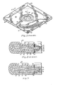
- FIG. 1 illustrates a floppy disk assembly referred to by the general reference number 20.
- the assembly 20 includes an envelope 25 and a circular, flexible recording disk 27.
- the circular disk 27 has a central axis 28 normal to its planar surface and a circular aperture 29 having a diameter "D a " centred about the axis 28.
- the envelope 25, into which the circular disk 27 is inserted and sealed, is formed from a sheet of material fabricated by bonding a liner 31 made from porous, low-friction, antistatic material to a layer of solid material 33.
- the envelope 25 has a circular aperture 35 located about its centre and an oval aperture 37 located symmetrically about a line from the centre of the circular aperture 35 orthogonal to a side of the envelope 25.
- the aperture 35 is larger in diameter than the circular aperture 29 in the flexible recording disk 27.
- an annular-shaped reinforcement member 39 Secured to one or both side surfaces of the flexible recording disk 27 about its central aperture 29 and contained within the aperture 35 of the envelope 25 is an annular-shaped reinforcement member 39.
- a means for rotating the circular disk 27, such as a spindle passes through the circular aperture 35 and partially through the circular aperture 29 to engage the circular disk 27 and to rotate it about its centre.
- a transducing means is inserted through the oval aperture 37 to contact the recording surface of the circular disk 27.
- the flexible recording disk 27, shown in cross-section in Figure 2 is fabricated by applying a coating 41 comprised of small particles of magnetic material, a binder and a lubricant, to one or both sides of a sheet of flexible material 45.
- a coating 41 comprised of small particles of magnetic material, a binder and a lubricant
- the punched reinforcement member 39 is bonded to the surface of the coating 41 by means of an adhesive layer 47 located therebetween.
- the reinforcement member 51 formed on the surface of the flexible recording disk 27 in accordance with the teachings of this invention.
- the reinforcement member 51 comprises an integral, annular-shaped ring of polymerized polyolefin material surrounding the central aperture 29 which bonds directly to the coating 41.
- the first step in the process for forming the reinforcement member 51 is filling an open metering reservoir 61 recessed into a planar surface 63 of a plate 65 with a liquid 67.
- the reservoir 61 is filled by drawing a squeegee 69 across the surface 63 so as to drive a quantity of liquid 67 ahead of it thereby coating the surface 63 and over filling the reservoir 61.
- the quantity of liquid 67 in the reservoir 61 is established precisely and the surface 63 is cleansed of all liquid 67 by drawing a linear edge 75 of a knife blade 77 across the surface 63 as shown in Figure 5.
- the metering reservoir 61 is formed to have substantially the same shape as that desired for the reinforcement member 51.
- the metering reservoir 61 is annular-shaped having a uniformed depth into the plate 65, a width "W" and an inner diameter "D r " about a central axis 78 which is greater than the diameter "D a " of the central aperture 29 in the flexible recording disk 27.
- the inner diameter of "D of the annular-shaped reservoir 61 is generally formed to be 0.010 inches larger in diameter than the diameter of "D a" of the central aperture 29 and the width W of the annulus of the metering reservoir 61 is generally between three sixteenths to one quarter of an inch:
- the reservoir 61 is formed to have a depth such that the image transferred to the flexible recording disk 27 has a maximum thickness lying between three and five ten-thousandths of an inch (0.0003 to 0.0005).
- the liquid 67 to be coated on the surface 63 must be capable of subsequent solidification and preferably will be electrically conductive when so solidified. Further, the liquid 67 must not significantly dissolve the coating 41 and/or the flexible material 45 or interdiffuse into either of them thus causing them to swell.
- the liquid 67 comprises a mixture including cross-linkable, non-solvent based polyolefin monomer material in combination with a cross-linking agent, such as a peroxide material.
- a cross-linking agent such as a peroxide material.
- Such a mixture of monomer and cross-linking agent is UV8404 manufactured by Solex Corporation.
- One property of this class of materials is that exposure to ultraviolet radiation produces free radicals which cause the monomer to polymerize.
- the frictional properties of these materials when solidified, may be reduced by the addition thereto of slip agents such as long chain fatty acids or long chain fatty acid esters of hydrocarbons having twelve or more carbon atoms.
- the electrical conductive properties of these materials when solidified, may be enhanced by the addition thereto of finely divided particles of carbon such as graphite or of conductive metals is as well known in the art.
- the liquid 67 also contains surfactants and is vacuum degassed to removed entrained gases therefrom prior to being coated on the surface 63. This is done to assure uniform coverage of the transferred image. Good quality transferred images are obtained if a fifty milliliter quantity of UV8404 is degassed for approximately five minutes.
- the liquid 67 is then removed therefrom. As shown in Figure 6, this is done by contacting the surface 63 about the reservoir 61 with a terminal end surface 81 of a compliant tampon 83.
- a wide variety of shapes may be successfully employed for the end surface 81 of the tampon 83 such as spherical sections and planar sections.
- the tampon 83 is annular-shaped about a cylindrical axis 85 to have an inner cylindrical surface 87 and an outer cylindrical surface 89.
- the end surface 81 of the tampon 83 is shaped to be a conic section whose axis is colinear with that of the axis 85.
- the end surface 81 is formed so that its common circular edge with the inner surface 87 may contact the plate 65 first and its common circular edge with the outer surface 89 may contact the plate 65 last.
- the tampon 83 is formed so that the inner surface 87 has a diameter "D t " greater than the diameter "D a of the central aperture 29 in the flexible recording disk 27.
- the tampon 83 is fabricated from a material to have a Shore A hardness lying between one and two so as to render it extremely compliant.
- the tampon 83 may be fabricated by casting a suitable liquid silicone rubber material onto a disk-shaped metallic backing plate 91. If fabricated by casting, the end surface 81 will generally be coated with mold release.
- the mold release Before the tampon 83 may be put into service, the mold release must be cleaned from the surface 81 by means of an aromatic solvent such as laquer thinner which does nt adversely effect the properties of the cast silicone rubber.
- an aromatic solvent such as laquer thinner which does nt adversely effect the properties of the cast silicone rubber.
- the tampon 83 In contacting the surface 63, the tampon 83 is positioned so that its cylindrical axis 85 is essentially colinear with the axis 71 of the reservoir 61.
- the flexible recording disk 27 is prepared to receive the liquid 67, now carried by the end surface 81 of the tampon 83, by being positioned on a planar end surface 95 of an anvil 97 as shown in Figure 8.
- the end surface 95 of the anvil 97 is formed to have a raised cylindrically-shaped registration member 99 formed so as to fit snugly within the central aperture 29 of the flexible recording disk 27.
- the tampon 83 is then brought into contact with the exposed surface of the flexible recording disk 27 so that the cylindrical axis 85 is colinear with the axis 28 of the aperture 29 as shown in Figure 9.
- the end surface 81 of the tampon 83 applies the liquid 67 to the coating 41 of the flexible recording disk 27 to have substantially the same shape as that of the reinforcing member 51 being fabricated.
- the tampon 83 is then removed from contact with the flexible recording disk 27 and the disk 27 is removed from the anvil 97.
- the liquid 67, now carried by the disk 27, is then hardened to form the reinforcement member 51.
- the polyolefin monomer of the liquid 69 is hardened to form the reinforcement member 51 by exposure to ultraviolet radiation from a lamp 101 as shown in Figure 11 which causes the material to polymerize.
- an ultraviolet light source emitting radiation having wave lengths lying between 260 to 365 nanometers is used.
- the method of this invention may be used to form a reinforcement member 51 on a second side of the flexible recording disk 27 ; once the member 51 on the first side has been hardened.
- Flexible recording disks 27 having a reinforcement member 51 exhibit enhanced mechanical properties over those fabricated in accordance with the teachings of the prior art in several ways.
- a first improvement is that since the reinforcement member 51 is one solid piece of polymerized polyolefin, the possibility of contaminating the spindle of the apparatus for reading and writing floppy disk assemblies 20 is eliminated.
- flexible recording disks 27 having reinforcement members 51 exhibit a 50% reduction in the average change of the diameter "D a of the central aperture 29 brought about by temperature cycling the flexible recording disk from -40° C to +51.6° C.
- the improved mechanical stability of the central aperture 29 may be attributed to the fact that polyolefins have a lower coefficient of expansion than the polyester material normally used for the sheet of flexible material 45 and the material normally employed for the coating 41 and because the reinforcement member 51 is rigidly bonded thereto.
- the enhanced mechanical stability of the central aperture 29 serves to reduce the possibility of recording track misregistration for flexible recording disks 27 having reinforcement members 51.
- the integral structure of the reinforcement member 51 assures that its electrical conductivity properties will be determined solely by its geometrical shape and by the properties of the material from which it is fabricated.
- Such a reinforcement will be immune to changes in electrical conductivity as might be caused by contamination adhering to adhesive 47 oozing out from between the surface of the flexible recording disk 27 and the reinforcement member 39 of the
- flexible recording disks 27 having reinforcement members 51 are more easily centred about the spindle of the apparatus for reading and writing floppy disk assemblies 20 during insertion thereof than those constructed in accordance with prior art methods.
- the addition of friction reducing agents to the liquid 67 permits fabricating reinforcement members 51 having frictional properties precisely controlled by the formulation thereof.
- the addition of flow agents to the liquid 67 permits close control of the surface smoothness and of the curvature of the edge of the reinforcement member 51. Since the material forming the member 51 is liquid until hardened and also because of the method by which the liquid 67 is applied, it is impossible for the member 51 thus formed to have sharply defined corners and substantially vertical edge surfaces as will generally be found on the punched reinforcement members 39 of the prior art.
Landscapes
- Magnetic Record Carriers (AREA)
- Manufacturing Of Magnetic Record Carriers (AREA)
Applications Claiming Priority (2)
| Application Number | Priority Date | Filing Date | Title |
|---|---|---|---|
| US06/208,516 US4387114A (en) | 1980-11-20 | 1980-11-20 | Spindle aperture reinforcement for a floppy disk |
| US208516 | 1980-11-20 |
Publications (3)
| Publication Number | Publication Date |
|---|---|
| EP0052865A2 true EP0052865A2 (de) | 1982-06-02 |
| EP0052865A3 EP0052865A3 (en) | 1982-12-08 |
| EP0052865B1 EP0052865B1 (de) | 1986-02-19 |
Family
ID=22774874
Family Applications (1)
| Application Number | Title | Priority Date | Filing Date |
|---|---|---|---|
| EP81109776A Expired EP0052865B1 (de) | 1980-11-20 | 1981-11-19 | Verstärkung für die Zentrieröffnung einer Floppy-Disk |
Country Status (4)
| Country | Link |
|---|---|
| US (1) | US4387114A (de) |
| EP (1) | EP0052865B1 (de) |
| JP (1) | JPS57113422A (de) |
| DE (1) | DE3173838D1 (de) |
Cited By (2)
| Publication number | Priority date | Publication date | Assignee | Title |
|---|---|---|---|---|
| US4868699A (en) * | 1985-03-27 | 1989-09-19 | Automation Facilities Limited | Microfloppy disc drive head cleaner |
| GB2299699A (en) * | 1995-04-03 | 1996-10-09 | Ivan Yung Chih Lin | Damping vibrations of a compact disc during playing thereof |
Families Citing this family (18)
| Publication number | Priority date | Publication date | Assignee | Title |
|---|---|---|---|---|
| JPS6022785A (ja) * | 1983-07-18 | 1985-02-05 | Fuji Photo Film Co Ltd | フレキシブル磁気デイスク |
| JPS6025074A (ja) * | 1983-07-21 | 1985-02-07 | Fuji Photo Film Co Ltd | フレキシブル磁気デイスク |
| US4539220A (en) * | 1983-09-23 | 1985-09-03 | Verbatim Corporation | Method of manufacturing reinforced flexible disks |
| JPS6080132A (ja) * | 1983-10-07 | 1985-05-08 | Fuji Photo Film Co Ltd | フレキシブル磁気デイスク保護層の形成方法 |
| JPS60109031A (ja) * | 1983-11-17 | 1985-06-14 | Fuji Photo Film Co Ltd | フレキシブル磁気ディスク |
| JPS60111340A (ja) * | 1983-11-21 | 1985-06-17 | Fuji Photo Film Co Ltd | フレキシブル磁気デイスク |
| JPH0695433B2 (ja) * | 1984-02-29 | 1994-11-24 | 富士写真フイルム株式会社 | フレキシブル磁気デイスク |
| US4707392A (en) * | 1984-02-29 | 1987-11-17 | Fuji Photo Film Co., Ltd. | Flexible magnetic disk |
| JPH0685267B2 (ja) * | 1984-05-07 | 1994-10-26 | 富士写真フイルム株式会社 | フレキシブル磁気デイスク |
| JPS61115238A (ja) * | 1984-11-09 | 1986-06-02 | Fuji Photo Film Co Ltd | フレキシブル磁気デイスクとその製造方法 |
| JPS626476A (ja) * | 1985-07-02 | 1987-01-13 | Kasei Baabeitamu Kk | 補強リング貼付け装置 |
| US4643730A (en) * | 1985-09-26 | 1987-02-17 | Kimberly-Clark Corporation | Radiation curing formulations for polyethylene film reinforcement to provide refastenable pressure-sensitive tape closure system for disposable diapers |
| US4952435A (en) * | 1985-10-03 | 1990-08-28 | Fuji Photo Film Co., Ltd. | Adhesive for a base-mounted flexible magnetic disc |
| JPS62248183A (ja) * | 1986-04-22 | 1987-10-29 | Semedain Kk | 磁気フロツピ−デイスクジヤケツト及びその製造方法 |
| JPS6337823A (ja) * | 1986-07-30 | 1988-02-18 | Columbia Magune Prod Kk | フレキシブル磁気デイスク及びその製造方法 |
| JP2517341B2 (ja) * | 1988-01-14 | 1996-07-24 | 三洋電機株式会社 | 光学式情報記録ディスクの製造方法 |
| JPH01315081A (ja) * | 1989-04-17 | 1989-12-20 | Fuji Photo Film Co Ltd | フレキシブル磁気デイスク |
| JP2687245B2 (ja) * | 1989-09-29 | 1997-12-08 | 富士写真フイルム株式会社 | 磁気記録媒体の製造方法 |
Family Cites Families (7)
| Publication number | Priority date | Publication date | Assignee | Title |
|---|---|---|---|---|
| US1155352A (en) * | 1914-07-24 | 1915-10-05 | Jacob Grass | Lithographic plate for offset and direct printing. |
| US3951264A (en) * | 1974-10-29 | 1976-04-20 | Dynastor, Inc. | Flexible disc cartridge |
| JPS5728298Y2 (de) * | 1975-07-11 | 1982-06-21 | ||
| US4052750A (en) * | 1975-12-05 | 1977-10-04 | Dysan Corporation | Flexible recording disk with improved spindle mounting means |
| US4175274A (en) * | 1977-11-03 | 1979-11-20 | Texas Instruments Incorporated | Recording system with flexible magnetic recording disc |
| US4209551A (en) * | 1977-12-28 | 1980-06-24 | Toppan Printing Co., Ltd. | Method of fabricating a phosphor screen of a color television picture tube |
| JPS54123922A (en) * | 1978-03-17 | 1979-09-26 | Matsushita Electric Ind Co Ltd | Magnetic recording medium |
-
1980
- 1980-11-20 US US06/208,516 patent/US4387114A/en not_active Expired - Lifetime
-
1981
- 1981-11-19 JP JP56184527A patent/JPS57113422A/ja active Granted
- 1981-11-19 DE DE8181109776T patent/DE3173838D1/de not_active Expired
- 1981-11-19 EP EP81109776A patent/EP0052865B1/de not_active Expired
Cited By (2)
| Publication number | Priority date | Publication date | Assignee | Title |
|---|---|---|---|---|
| US4868699A (en) * | 1985-03-27 | 1989-09-19 | Automation Facilities Limited | Microfloppy disc drive head cleaner |
| GB2299699A (en) * | 1995-04-03 | 1996-10-09 | Ivan Yung Chih Lin | Damping vibrations of a compact disc during playing thereof |
Also Published As
| Publication number | Publication date |
|---|---|
| JPS57113422A (en) | 1982-07-14 |
| US4387114A (en) | 1983-06-07 |
| DE3173838D1 (en) | 1986-03-27 |
| EP0052865B1 (de) | 1986-02-19 |
| JPS6343809B2 (de) | 1988-09-01 |
| EP0052865A3 (en) | 1982-12-08 |
Similar Documents
| Publication | Publication Date | Title |
|---|---|---|
| US4387114A (en) | Spindle aperture reinforcement for a floppy disk | |
| US4124672A (en) | Replication utilizing a casting process | |
| US6404730B2 (en) | Optical disk having a groove and a projection for combining two disk members | |
| KR100284728B1 (ko) | 광 디스크 제조방법 및 이 제조방법에 의한 광 디스크 | |
| US3954469A (en) | Method of creating a replicating matrix | |
| US4609963A (en) | Spindle aperture reinforcement for a floppy disk | |
| EP2105920A1 (de) | Druckformstruktur und Druckverfahren damit und Verfahren zur Herstellung eines magnetischen Aufzeichnungsmediums | |
| JP2002074656A (ja) | 磁気転写方法 | |
| US7667908B2 (en) | Magnetic transfer method for perpendicular magnetic recording medium, perpendicular magnetic recording medium, and magnetic recording apparatus | |
| US4788615A (en) | Means for adhering the magnetic disk to the center core in a magnetic disk cartridge | |
| US4415138A (en) | Elastomeric videodisc mold | |
| JPS5836417A (ja) | 情報担体の製造方法 | |
| JPH0254447A (ja) | 光学的記録媒体用基板の製造方法 | |
| JPS62117154A (ja) | レプリカの転写・剥離装置 | |
| JPS59111820A (ja) | 光情報担体デイスクの製造方法 | |
| JP2774877B2 (ja) | 光ディスクの製造方法 | |
| JP2759059B2 (ja) | 磁気記録装置 | |
| JPS60217544A (ja) | ディジタル信号再生用テストディスクの製造方法 | |
| JPS58153242A (ja) | 音盤・記録盤用原盤の製造方法 | |
| JPH01264644A (ja) | 光デイスク基板の製造方法 | |
| US20090244762A1 (en) | Resist pattern forming method, mold structure producing method, magnetic recording medium producing method, magnetic transfer method and magnetic recording medium | |
| JP2700497B2 (ja) | 磁気記録媒体及びその製造方法 | |
| JPH0816980B2 (ja) | 磁気デイスク基板およびその製造方法 | |
| JP2001054922A (ja) | 金型装置及びディスク基板 | |
| JPH0335403A (ja) | 磁気ヘッド |
Legal Events
| Date | Code | Title | Description |
|---|---|---|---|
| PUAI | Public reference made under article 153(3) epc to a published international application that has entered the european phase |
Free format text: ORIGINAL CODE: 0009012 |
|
| AK | Designated contracting states |
Designated state(s): DE FR GB IT SE |
|
| PUAL | Search report despatched |
Free format text: ORIGINAL CODE: 0009013 |
|
| AK | Designated contracting states |
Designated state(s): DE FR GB IT SE |
|
| 17P | Request for examination filed |
Effective date: 19830516 |
|
| GRAA | (expected) grant |
Free format text: ORIGINAL CODE: 0009210 |
|
| ITF | It: translation for a ep patent filed | ||
| AK | Designated contracting states |
Designated state(s): DE FR GB IT SE |
|
| REF | Corresponds to: |
Ref document number: 3173838 Country of ref document: DE Date of ref document: 19860327 |
|
| ET | Fr: translation filed | ||
| PLBE | No opposition filed within time limit |
Free format text: ORIGINAL CODE: 0009261 |
|
| STAA | Information on the status of an ep patent application or granted ep patent |
Free format text: STATUS: NO OPPOSITION FILED WITHIN TIME LIMIT |
|
| 26N | No opposition filed | ||
| PGFP | Annual fee paid to national office [announced via postgrant information from national office to epo] |
Ref country code: DE Payment date: 19881230 Year of fee payment: 8 |
|
| PG25 | Lapsed in a contracting state [announced via postgrant information from national office to epo] |
Ref country code: GB Effective date: 19891119 |
|
| GBPC | Gb: european patent ceased through non-payment of renewal fee | ||
| PG25 | Lapsed in a contracting state [announced via postgrant information from national office to epo] |
Ref country code: FR Effective date: 19900731 |
|
| PG25 | Lapsed in a contracting state [announced via postgrant information from national office to epo] |
Ref country code: DE Effective date: 19900801 |
|
| REG | Reference to a national code |
Ref country code: FR Ref legal event code: ST |
|
| PGFP | Annual fee paid to national office [announced via postgrant information from national office to epo] |
Ref country code: SE Payment date: 19901128 Year of fee payment: 10 |
|
| ITTA | It: last paid annual fee | ||
| REG | Reference to a national code |
Ref country code: GB Ref legal event code: 728C |
|
| REG | Reference to a national code |
Ref country code: GB Ref legal event code: 728R |
|
| PG25 | Lapsed in a contracting state [announced via postgrant information from national office to epo] |
Ref country code: SE Effective date: 19911120 |
|
| EUG | Se: european patent has lapsed |
Ref document number: 81109776.5 Effective date: 19920604 |