EP0034717B1 - Véhicule ou container, en particulier wagon pour marchandises - Google Patents
Véhicule ou container, en particulier wagon pour marchandises Download PDFInfo
- Publication number
- EP0034717B1 EP0034717B1 EP81100600A EP81100600A EP0034717B1 EP 0034717 B1 EP0034717 B1 EP 0034717B1 EP 81100600 A EP81100600 A EP 81100600A EP 81100600 A EP81100600 A EP 81100600A EP 0034717 B1 EP0034717 B1 EP 0034717B1
- Authority
- EP
- European Patent Office
- Prior art keywords
- lever
- vehicle
- adjusting lever
- container according
- articulated
- Prior art date
- Legal status (The legal status is an assumption and is not a legal conclusion. Google has not performed a legal analysis and makes no representation as to the accuracy of the status listed.)
- Expired
Links
- 230000008878 coupling Effects 0.000 claims description 8
- 238000010168 coupling process Methods 0.000 claims description 8
- 238000005859 coupling reaction Methods 0.000 claims description 8
- 206010037660 Pyrexia Diseases 0.000 claims 1
- 230000000284 resting effect Effects 0.000 claims 1
- 230000008901 benefit Effects 0.000 description 3
- 241001295925 Gegenes Species 0.000 description 2
- 238000013461 design Methods 0.000 description 2
- 238000013459 approach Methods 0.000 description 1
- 230000005540 biological transmission Effects 0.000 description 1
- 230000015572 biosynthetic process Effects 0.000 description 1
- 238000011161 development Methods 0.000 description 1
- 210000003746 feather Anatomy 0.000 description 1
- 230000005484 gravity Effects 0.000 description 1
- 238000003780 insertion Methods 0.000 description 1
- 230000037431 insertion Effects 0.000 description 1
- 230000003993 interaction Effects 0.000 description 1
- 238000004519 manufacturing process Methods 0.000 description 1
- 230000007246 mechanism Effects 0.000 description 1
- 238000000034 method Methods 0.000 description 1
- 230000008569 process Effects 0.000 description 1
- 230000006641 stabilisation Effects 0.000 description 1
- 238000011105 stabilization Methods 0.000 description 1
Images


Classifications
-
- B—PERFORMING OPERATIONS; TRANSPORTING
- B61—RAILWAYS
- B61D—BODY DETAILS OR KINDS OF RAILWAY VEHICLES
- B61D39/00—Wagon or like covers; Tarpaulins; Movable or foldable roofs
- B61D39/002—Sliding or folding roofs
- B61D39/003—Sliding or folding roofs telescopic
-
- B—PERFORMING OPERATIONS; TRANSPORTING
- B61—RAILWAYS
- B61D—BODY DETAILS OR KINDS OF RAILWAY VEHICLES
- B61D19/00—Door arrangements specially adapted for rail vehicles
-
- B—PERFORMING OPERATIONS; TRANSPORTING
- B61—RAILWAYS
- B61D—BODY DETAILS OR KINDS OF RAILWAY VEHICLES
- B61D39/00—Wagon or like covers; Tarpaulins; Movable or foldable roofs
- B61D39/006—Opening and closing means
-
- E—FIXED CONSTRUCTIONS
- E05—LOCKS; KEYS; WINDOW OR DOOR FITTINGS; SAFES
- E05Y—INDEXING SCHEME RELATING TO HINGES OR OTHER SUSPENSION DEVICES FOR DOORS, WINDOWS OR WINGS AND DEVICES FOR MOVING WINGS INTO OPEN OR CLOSED POSITION, CHECKS FOR WINGS AND WING FITTINGS NOT OTHERWISE PROVIDED FOR, CONCERNED WITH THE FUNCTIONING OF THE WING
- E05Y2201/00—Constructional elements; Accessories therefore
- E05Y2201/20—Brakes; Disengaging means, e.g. clutches; Holders, e.g. locks; Stops; Accessories therefore
- E05Y2201/23—Actuation thereof
- E05Y2201/232—Actuation thereof by automatically acting means
- E05Y2201/234—Actuation thereof by automatically acting means direction dependent
-
- E05Y2400/3013—
Definitions
- the invention relates to a vehicle or a container, in particular a railway freight wagon, in which two sliding wall parts opposite each other in the transverse direction are each held at the bottom in guides in a pivotable and longitudinally displaceable manner and are articulated at the top via a swivel body with a roof shell extending in the length of these wall parts, the Carry out lifting and swiveling movements in the upper area by rotating the swivel body using an actuator.
- the invention has for its object to provide for a vehicle or a container of the generic type as simple and compact as possible, on the drive side with short paths and on the output side operating under limited space.
- the actuating device for each swivel body has a pivot lever formed from a pivot lever and an adjusting lever, of which the pivot lever is pivotally mounted about a fixed point on the vehicle and the adjusting lever is connected to a drive and pulling force supply drive, the Linkage lever and the adjusting lever at their ends facing away from the fixed point or from the point of application of the drive are rotatably connected to one another by arranging a first coupling which limits the angle of rotation of the adjusting lever and between the adjusting lever and a driver which engages in a form-fitting manner in the swivel body, one with a clearance angle for rotary movements the driver formed second clutch is arranged.
- the Anienkhebel is provided with a socket-like head for rotatably receiving a socket-like body of the adjusting lever, the socket-like head of the Hinged lever has stop surfaces for limiting the angle of rotation of the adjusting lever, and that - to form the second coupling - a circular segment-shaped approach of an angularly rigid driver sleeve protrudes into the circular path of an arcuate projection formed on the sleeve-like body of the adjusting lever.
- the driver is connected to the adjusting lever so as to be movable in the longitudinal direction in order to separate or create the positive engagement in the swivel body.
- the positive connection between a rigidly arranged driver and the swivel body is inevitably separated or created by longitudinally displacing the swung-out sliding wall parts with the raised roof shell for opening or closing, for example the freight wagon.
- sudden forces may act on the driver and the downstream adjusting lever.
- the above-mentioned longitudinally movable connection of the driver to the adjusting lever advantageously allows said positive engagement to be separated and created when the sliding wall parts are at rest with the roof shell, thereby avoiding such abrupt forces.
- a supplementary embodiment according to the invention is that the drive is articulated with a hinge on the adjusting lever and engages the driver Swivel piece is connected, wherein a lock also mounted on the adjusting lever in its locked position unites the swivel piece with the adjusting lever and in its released position allows the swivel piece to pivot in the sense of the longitudinal movements of the driver.
- an additional feature according to the invention provides that the lock runs against a stationary web shortly before reaching the end position of the articulation lever belonging to the open position of the roof shell and the sliding wall parts.
- a further embodiment of the invention consists in that the adjusting lever is locked when the driver is out of engagement in the swivel body by a locking lever which is articulated on the end wall and can be released by inserting the driver into the swivel body.
- a securing body mounted on the end wall is provided, which engages behind the adjusting lever as soon as the sliding wall parts with the roof shell are pushed in the direction of the open position, and by moving the sliding wall parts with the roof shell back into the closed position of the adjusting lever has the starting position.
- the common for the pivot lever formed from the pivot lever and the adjusting lever drive from both sides of the vehicle or container from independently operable operating means, for. B. cranks.
- a further idea according to the invention is that the articulation lever which is rotatable about the fixed point is movably supported in the region facing away from this fixed point against a guide bar fastened to the end wall in the transverse direction.
- a next embodiment according to the invention provides that the roof shell has a fork-like receptacle for a vertically movably mounted end wall on the end wall side, via which the pulling and compressive force drive can be raised and lowered guide body.
- the lifting and lowering of the guide body provided in a simple manner by means of the actuating device provides the advantage that a boundary profile that is valid for rail vehicles is maintained when the portal is closed.
- the guide body is connected via a lever group to a driven handlebar which acts on the adjusting lever.
- the guide body has a closing profile which bears against the top of the receptacle on the roof shell.
- a supplementary feature according to the invention is that the receptacle on the roof shell has converging contact surfaces for the guide body towards the transverse center of the vehicle or the container. This results in an exact, bumpless joining of the swivel body and the driver.
- a convenient, smooth bearing of the guide body is achieved in that the guide body is designed as a tube and is designed to be concave on its outer surface by means of a rotatable end wall Rolls is stored.
- the actuating device is simple and compact, which also benefits its placement on the vehicle or on the container and its functional reliability, with a full lifting or swiveling movement of the roof shell and the Sliding wall parts resulting rotation of the pivot body by approximately 180 ° is generated only by moving the pivot lever formed from the adjusting lever and the link lever within a comparatively small pivot angle.
- the side walls each consist of two sliding wall parts 1.
- the car roof is formed by two roof shells 2, each of which extends in the length of a sliding wall part 1 and is articulated to the wall parts 1 opposite in the transverse direction of the car via swivel bodies 3.
- the two portals formed in this way can be guided into an open position by rotating the associated swivel bodies by almost 180 ° and in space - see in particular FIG. 2 - and by moving the lower guide elements 4 described below (see FIG. 3) into an open position Allows longitudinal shifting of the corresponding portal over the other portal in the closed position.
- the lower guide elements 4 contain a shaft 4a with swivel arms 4b attached to them, each of which engages in a mounting of carriages 1a provided with rollers 1b on the sliding wall part 1.
- the sliding wall part 1 is supported in the closed position via a web 1 c on its carriage 1a on a long beam 5a of the carriage underframe 5 and - after the shaft 4a has been moved - in the open position on a track 5b lying in front of the shaft 4a on the underframe 5 is held in a longitudinally displaceable manner.
- each portal according to FIG. 2 is held in the closed position by the swivel body 3 being above the dead center position, that is to say without the interlocks otherwise required.
- a flange 2a of this shell 2 and a flange 1d of the sliding wall part 1 rest against the respective swivel body 3 under the weight of the roof shell 2 in the sense of stabilization, with additional protection against movement of the opened sliding wall parts 1 in the direction of a longitudinal bracket 3a is mounted on the end of the car body at the end wall end of the swivel body 3 and acts against a nose 1e on the sliding wall part 1.
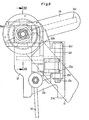
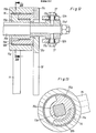
- the actuating device - see initially FIG. 4 - for the aforementioned rotation of the swivel body 3 and the movement of the shafts 4a of each portal is mounted on the corresponding end wall of the freight wagon and is configured as follows:
- Wa Gense i te forth For convenient access from each Wa Gense i te forth are two, with handwheel or crank 6a provided operation shafts 6 (see also Fig. 14) via plug-in connectors 6b independently of one another with a bottom, the direction of force deflecting transmission 7, here a bevel gear 7, connectable.
- a drive shaft 8 is used to connect an upper worm gear 9 to the lower bevel gear 7.
- the worm gear 9 carries on the output side a rotary lever 9a, the ends of which each hold a handlebar 10, preferably by means of a ball head.
- a further bevel gear 7a is provided according to FIG. 15, which cooperates with the respective handlebar 10 via a threaded spindle 7b with nut 7c.
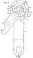
- each handlebar rod 10 is operatively connected to a pivot lever, which is formed from an arm lever 11 and an adjusting lever 12 and is shown as an individual part in FIGS. 5 and 6.
- the articulation lever 11 is rotatable about a fixed point 13 on the end wall and is supported in a region facing away from the fixed point 13 against a guide bar 25 fastened on the end wall (see FIG. 7).
- the articulation lever 11 has a bush-like head 11a which has a stop surface 11 for the adjusting lever 12 which delimits a recess in this head 11a, as a result of which a first coupling which limits the angle of rotation of the adjusting lever 12 is formed.
- the bush-like head 11a of the articulation lever 11 receives a likewise bush-like body 12a of the adjusting lever 12 with the interposition of a sliding bush 14.
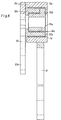
- a second coupling there is an arcuate projection 12b on the socket-like body 12a of the adjusting lever 12, in the circular path of which a projection 15b in the form of a segment of a driver bush 15a protrudes.
- the driver bush 15a is mounted via a further inner slide bush 14a in the bush-like body 12a of the adjusting lever 12 and is connected in a rotationally fixed manner via a feather key to the one end of a driver 15, shown in particular in FIG.
- a connecting lever 19 is articulated on the articulation lever 11 of each pivoting lever in view of the pivoting out and inward pivoting of the associated sliding wall part 1, which actuates a lifting rod 21 via a rigid angle lever 20.
- the lifting rod 21 engages an arm 4c attached to the end wall on the shaft 4a for rotating this shaft 4a.
- the actuating device works in the following way: The movement initiated to open a portal with one of the operating shafts 6 passes through bevel gear 7, drive shaft 8, worm gear 9, rotary lever 9a and the handlebars 10 to the adjusting levers 12 of the two swivel levers, which in the direction of the Link lever 11 are pressed.
- the respective adjusting lever 12 rotates within the bush-like head 11a of the articulation lever 11 which initially remains in its position; the arcuate projection 12b of the body 12a on the adjusting lever 12 acts against the segment 15b of the driver bush 15a, so that ultimately the pivot body 3 executes the corresponding rotational movement about its wall-side axis of rotation 3b via the driver 15 connected to this bush 15a.
- the angle of rotation of the adjusting lever 12 is limited by the right abutment surface 11 b on the head 11 a of the articulation lever 11 in the drawing plane of FIG. 5.
- the abovementioned stop surface 11b is arranged such that, when the limitation has taken place, the swivel body 3 has in any case come from its over-dead center position into the closed position in a position which permits the swivel body 3 to be rotated further by swiveling the articulation lever 11 about the fixed point 13 on the end wall.
- the wall-side axis of rotation 3b reaches the outside in an almost straight line and the roof-side axis of rotation Axis 3c also upwards until the swivel body is approximately vertical in a new dead center and subsequently swings into the open position.
- the segment 15b of the driver bush 15a lifts off from one side of the arcuate projection 12b of the body 12a on the adjusting lever 12 and rests against the other side of the projection 12b in the open position.
- the adjusting lever 12 of the swivel lever is again operated first; the driver bush 15a is rotated by the aforementioned interaction of the arcuate projection 12b with the segment 15b in the form of a segment of a circle, and the swivel body is moved approximately into its vertical position about its wall-side axis of rotation 3b.
- the left stop surface 11b in FIG. 5 on the head 11a of the articulation lever 11 limits the angle of rotation of the adjustment lever 12. The closing ends when the articulation lever 11 is pivoted back.
- the adjusting lever 12 is provided with a support plate 12c which receives a bolt 12e for a swivel piece 12f in bearing eyes 12d.
- the handlebar rod 10 of the drive engages a swivel fork 12g of the swivel piece 12f.
- a lock 16 mounted on the support plate 12c of the adjusting lever 12 ensures that the pivot piece 12f cannot initially rotate about the bolt 12e.
- a driving fork 12h of the swivel piece 12f is used for the rotatable fastening - for this purpose screws 17 and sleeves 17a - of a bearing bush 15d, which holds the end facing away from the flat 15c of the driving member 15.
- the driver 15 is here connected in a rotationally fixed manner to the driver bush 15a via a shaft 15e which is square in cross section.
- the portal is opened in the manner already described, i.e. by turning the adjusting lever 12, here with the support plate 12c, and moving the articulation lever 11 around the fixed point 13 on the end wall.
- the lock 16 runs against a web 18 shortly before the articulation lever 11 reaches the end position on the end wall (see Fig. 7) and ultimately releases the pivot piece 12f.
- the swivel piece 12f is rotated about the bolt 12e until the sleeves 17a in the driving fork 12h of the swivel piece 12f have passed through the curved path 12j located in this fork 12h (see FIG. 11).
- the flattened portion 15c of the driver 15 is pulled out of the swivel body and brought into a position that lies outside the run-up level of the retracted portal.
- the insertion of the driver 15 into the swivel body 3 is accordingly reversed and before the explained closing of the portal.
- a securing body 22 is shown in the operative position with the longitudinally displaced portal, which locks the adjusting lever 12 in this position of the portal.
- this securing body 22 is rotatably mounted on a bracket 23 of the end wall and moves automatically through a counterweight 22a when the portal is moved longitudinally to open it; a web 22b of the securing body 22 then engages behind a nose 12k which, according to FIG. 5, is located directly on the adjusting lever 12 and according to FIGS. 7 and 9 on its supporting plate 12c.
- the portal guides the securing body 22 back against the force of the counterweight 22b into the starting position, not shown, via a trigger 3d shown in FIG. 1, which is fastened to the folding bracket 3a.
- a further safety lever 24 shown in FIG. 8 ensures, independently of the safety body 22, that the adjusting lever 12 can only be moved back when the driver 15 has positively engaged in the swivel body 3.
- This safety lever 124 is also mounted on the end wall outside its center of gravity, is tilted when the articulation lever 11 is moved into the open position via an inclined surface 121 on the support plate 12c of the adjusting lever 12 (see FIG. 11) and finally snaps behind one at the end of the inclined surface 121 on the support plate 12c
- Adjusting lever 12 (see FIG. 11) is tilted and finally snaps behind a cam 12m located at the end of inclined surface 121.
- a mandrel 12 attached to the swivel piece 12f of the adjusting lever 12 guides the safety lever 24 back into its initial position when the positive connection between the driver 15 and the swivel body 3 is formed and then enables the closing process.
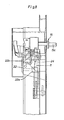
- FIGS. 15 and 16 forms in particular a guide for the roof shell 2 during its lifting movements.
- the roof shell 2 is provided with a fork-like receptacle 2b for a guide body 26 located on the end wall 29, which is mounted so as to be vertically movable via rollers 28 which are rotatably fastened there and have a concave design on their outer surface.
- the guide body 26 has an end profile 26a which bears against the top of the receptacle 2b on the roof shell 2. As a result, a holder for the closed roof shell 2 is formed.
- the bevels 2c of the receptacle 2b shown in FIG. 16, together with the guide body 26, position the roof shell 2 in particular when the portal is pushed shut.
Claims (15)
Priority Applications (1)
| Application Number | Priority Date | Filing Date | Title |
|---|---|---|---|
| AT81100600T ATE4634T1 (de) | 1980-02-20 | 1981-01-28 | Fahrzeug oder behaelter, insbesondere eisenbahngueterwagen. |
Applications Claiming Priority (4)
| Application Number | Priority Date | Filing Date | Title |
|---|---|---|---|
| DE19803006371 DE3006371A1 (de) | 1980-02-20 | 1980-02-20 | Fahrzeug oder behaelter, insbesondere eisenbahngueterwagen |
| DE3006371 | 1980-02-20 | ||
| DE3041193 | 1980-11-03 | ||
| DE19803041193 DE3041193A1 (de) | 1980-11-03 | 1980-11-03 | Fahrzeug oder behaelter,insbesondere eisenbahng+terwagen |
Publications (2)
| Publication Number | Publication Date |
|---|---|
| EP0034717A1 EP0034717A1 (fr) | 1981-09-02 |
| EP0034717B1 true EP0034717B1 (fr) | 1983-09-14 |
Family
ID=25783824
Family Applications (1)
| Application Number | Title | Priority Date | Filing Date |
|---|---|---|---|
| EP81100600A Expired EP0034717B1 (fr) | 1980-02-20 | 1981-01-28 | Véhicule ou container, en particulier wagon pour marchandises |
Country Status (4)
| Country | Link |
|---|---|
| EP (1) | EP0034717B1 (fr) |
| DD (1) | DD156241A1 (fr) |
| DE (1) | DE3160857D1 (fr) |
| ES (1) | ES8201079A1 (fr) |
Families Citing this family (12)
| Publication number | Priority date | Publication date | Assignee | Title |
|---|---|---|---|---|
| DD209601B1 (de) * | 1982-07-14 | 1987-11-04 | Niesky Waggonbau Veb | Haubenverdeck fuer gueterwagen |
| GB2154195A (en) * | 1984-02-16 | 1985-09-04 | Ukf Fertilisers Limited | Railcar hinged side door |
| GB2154194A (en) * | 1984-02-16 | 1985-09-04 | Ukf Fertilisers Limited | Railcar door openable by fork-lift truck tine |
| GB2157246B (en) * | 1984-04-10 | 1987-11-25 | Structure Flex Limited | Retractable cover assembly for a load carrying vehicle |
| DD261053A3 (de) * | 1984-07-20 | 1988-10-19 | Niesky Waggonbau Veb | Spreizhaubenverdeck fuer gueterwagen und container |
| DD227100B1 (de) * | 1984-09-20 | 1988-10-19 | Niesky Waggonbau Veb | Haubenverdecke fuer gueterwagen und container |
| GB8628033D0 (en) * | 1986-11-24 | 1986-12-31 | Marmon Holdings Uk Ltd | Railway vehicle |
| DE4140347C2 (de) * | 1991-12-06 | 2001-09-27 | Dwa Deutsche Waggonbau Gmbh | Gedeckter Güterwagen, insbes. Doppelstockautotransportwagen |
| KR100498128B1 (ko) * | 2002-09-17 | 2005-07-01 | 최외수 | 철도용 유개 화차 |
| CN101797925B (zh) * | 2010-03-29 | 2012-02-08 | 南车眉山车辆有限公司 | 一种活动车顶锁闭装置 |
| FR3064579A1 (fr) * | 2017-03-30 | 2018-10-05 | Titagarh Wagons Afr | Liaison mecanique a double liaison pivot, et vehicule ferroviaire comportant une telle liaison mecanique |
| CN110667626A (zh) * | 2019-10-08 | 2020-01-10 | 中车太原机车车辆有限公司 | 一种铁路漏斗车通长侧开式顶盖 |
Citations (7)
| Publication number | Priority date | Publication date | Assignee | Title |
|---|---|---|---|---|
| DE923669C (de) * | 1952-02-12 | 1955-02-21 | Franz Kruckenberg Dipl Ing | Geschlossener Fahrzeugkoerper, insbesondere fuer Schienenfahrzeuge |
| DE1159990B (de) * | 1960-05-20 | 1963-12-27 | Pierre Jean Marie Theodore All | Gueterwagen, insbesondere fuer den Transport von Schuett- und Stueckgut |
| FR1451558A (fr) * | 1965-07-23 | 1966-01-07 | D Epluches Atel Const | Véhicule de charge à carrosserie ouvrante |
| DE1580997A1 (de) * | 1966-12-09 | 1971-12-16 | Orenstein & Koppel Ag | Gedeckter Gueterwagen |
| DE2133251A1 (de) * | 1970-11-13 | 1972-05-18 | Mini Verkehrswesen | Vorrichtung zum wahlweisen seitlichen Schwenken von Fahrzeugdaechern |
| DE1605032C3 (de) * | 1966-05-11 | 1975-06-19 | Waggonfabrik Uerdingen Ag, 4150 Krefeld-Uerdingen | Gedeckter Güterwagen mit im geschlossenen Zustand in einer Ebene liegenden Schiebewandteilen |
| EP0011195A1 (fr) * | 1978-11-15 | 1980-05-28 | Duewag Aktiengesellschaft | Véhicule ou container, en particulier wagon pour marchandises |
Family Cites Families (1)
| Publication number | Priority date | Publication date | Assignee | Title |
|---|---|---|---|---|
| US3520257A (en) * | 1967-03-15 | 1970-07-14 | Shunk Mfg Co Inc | Telescopic car covers |
-
1981
- 1981-01-28 DE DE8181100600T patent/DE3160857D1/de not_active Expired
- 1981-01-28 EP EP81100600A patent/EP0034717B1/fr not_active Expired
- 1981-02-12 DD DD81227590A patent/DD156241A1/xx not_active IP Right Cessation
- 1981-02-19 ES ES499587A patent/ES8201079A1/es not_active Expired
Patent Citations (8)
| Publication number | Priority date | Publication date | Assignee | Title |
|---|---|---|---|---|
| DE923669C (de) * | 1952-02-12 | 1955-02-21 | Franz Kruckenberg Dipl Ing | Geschlossener Fahrzeugkoerper, insbesondere fuer Schienenfahrzeuge |
| DE1159990B (de) * | 1960-05-20 | 1963-12-27 | Pierre Jean Marie Theodore All | Gueterwagen, insbesondere fuer den Transport von Schuett- und Stueckgut |
| FR1451558A (fr) * | 1965-07-23 | 1966-01-07 | D Epluches Atel Const | Véhicule de charge à carrosserie ouvrante |
| BE684499A (fr) * | 1965-07-23 | 1967-01-03 | ||
| DE1605032C3 (de) * | 1966-05-11 | 1975-06-19 | Waggonfabrik Uerdingen Ag, 4150 Krefeld-Uerdingen | Gedeckter Güterwagen mit im geschlossenen Zustand in einer Ebene liegenden Schiebewandteilen |
| DE1580997A1 (de) * | 1966-12-09 | 1971-12-16 | Orenstein & Koppel Ag | Gedeckter Gueterwagen |
| DE2133251A1 (de) * | 1970-11-13 | 1972-05-18 | Mini Verkehrswesen | Vorrichtung zum wahlweisen seitlichen Schwenken von Fahrzeugdaechern |
| EP0011195A1 (fr) * | 1978-11-15 | 1980-05-28 | Duewag Aktiengesellschaft | Véhicule ou container, en particulier wagon pour marchandises |
Also Published As
| Publication number | Publication date |
|---|---|
| ES499587A0 (es) | 1981-12-01 |
| EP0034717A1 (fr) | 1981-09-02 |
| ES8201079A1 (es) | 1981-12-01 |
| DE3160857D1 (en) | 1983-10-20 |
| DD156241A1 (de) | 1982-08-11 |
Similar Documents
| Publication | Publication Date | Title |
|---|---|---|
| EP0536528B1 (fr) | Dispositif de manoeuvre d'une porte pivotante-coulissante pour véhicules de transport en commun, notamment ferroviaires | |
| EP1621386B1 (fr) | Dispositif pare-vent | |
| AT501468B1 (de) | Schwenkschiebetür | |
| EP1372999B1 (fr) | Guide de porte coulissante comportant un chariot et un rail destine a des vehicules | |
| EP0034717B1 (fr) | Véhicule ou container, en particulier wagon pour marchandises | |
| DE19735181C2 (de) | Schwenkschiebetür für Fahrzeuge | |
| AT500017B1 (de) | Schwenkschiebetür für fahrzeuge | |
| DE3312001A1 (de) | Eisenbahngueterwagen | |
| DE19964066B4 (de) | Verschlusseinrichtung für ein Verdeck eines Fahrzeugs | |
| CH621976A5 (fr) | ||
| EP1907231A2 (fr) | Dispositif d'entrainement d'un composant deplaçable d'un vehicule | |
| DE102009018188B4 (de) | Vorrichtung zum automatischen Schließen einer Fahrzeugtür | |
| EP1103403A2 (fr) | Panneau ajustable dans le revêtement d'un véhicule | |
| DE10057872A1 (de) | Hardtop-Fahrzeugdach | |
| EP0083038A1 (fr) | Heurtoir pour des voies | |
| DE10132361C1 (de) | Vorrichtung zur Sicherung des Mechanismus zum Heben und Senken der Passagiertür eines Flugzeuges | |
| DE60304475T2 (de) | Zur erleichterung des einführens von objekten unter einem faltdach im kofferraum eines kraftfahrzeugs verwendete vorrichtung | |
| DE102008045903B4 (de) | Kraftfahrzeug mit Mechanismus zum Bewegen einer Klappe | |
| EP1017918B1 (fr) | Fermeture en forme de barre, presentant une course d'actionnement s'eloignant du vantail de porte | |
| DE3006371A1 (de) | Fahrzeug oder behaelter, insbesondere eisenbahngueterwagen | |
| EP0911199B1 (fr) | Porte pivotante coulissante | |
| DE4402978C2 (de) | Rücksitzlehne für Kraftfahrzeuge | |
| DE3145871A1 (de) | Anhaengerkupplungsvorrichtung eines lastzuges | |
| DD156241A2 (de) | Fahrzeug oder behaelter,insbesondere eisenbahngueterwagen | |
| DE19512384C2 (de) | Mittelpufferkupplung für Schienenfahrzeuge |
Legal Events
| Date | Code | Title | Description |
|---|---|---|---|
| PUAI | Public reference made under article 153(3) epc to a published international application that has entered the european phase |
Free format text: ORIGINAL CODE: 0009012 |
|
| 17P | Request for examination filed |
Effective date: 19810209 |
|
| AK | Designated contracting states |
Designated state(s): AT BE CH DE FR GB IT NL SE |
|
| RAP1 | Party data changed (applicant data changed or rights of an application transferred) |
Owner name: DUEWAG AKTIENGESELLSCHAFT |
|
| ITF | It: translation for a ep patent filed |
Owner name: SOCIETA' ITALIANA BREVETTI S.P.A. |
|
| GRAA | (expected) grant |
Free format text: ORIGINAL CODE: 0009210 |
|
| AK | Designated contracting states |
Designated state(s): AT BE CH DE FR GB IT LI NL SE |
|
| REF | Corresponds to: |
Ref document number: 4634 Country of ref document: AT Date of ref document: 19830915 Kind code of ref document: T |
|
| REF | Corresponds to: |
Ref document number: 3160857 Country of ref document: DE Date of ref document: 19831020 |
|
| PGFP | Annual fee paid to national office [announced via postgrant information from national office to epo] |
Ref country code: SE Payment date: 19831130 Year of fee payment: 4 |
|
| ET | Fr: translation filed | ||
| PGFP | Annual fee paid to national office [announced via postgrant information from national office to epo] |
Ref country code: FR Payment date: 19831216 Year of fee payment: 4 |
|
| PGFP | Annual fee paid to national office [announced via postgrant information from national office to epo] |
Ref country code: CH Payment date: 19840126 Year of fee payment: 4 |
|
| PLBE | No opposition filed within time limit |
Free format text: ORIGINAL CODE: 0009261 |
|
| STAA | Information on the status of an ep patent application or granted ep patent |
Free format text: STATUS: NO OPPOSITION FILED WITHIN TIME LIMIT |
|
| 26N | No opposition filed | ||
| PGFP | Annual fee paid to national office [announced via postgrant information from national office to epo] |
Ref country code: BE Payment date: 19841231 Year of fee payment: 5 |
|
| PGFP | Annual fee paid to national office [announced via postgrant information from national office to epo] |
Ref country code: DE Payment date: 19850104 Year of fee payment: 5 |
|
| PGFP | Annual fee paid to national office [announced via postgrant information from national office to epo] |
Ref country code: AT Payment date: 19860130 Year of fee payment: 6 |
|
| PGFP | Annual fee paid to national office [announced via postgrant information from national office to epo] |
Ref country code: NL Payment date: 19860131 Year of fee payment: 6 |
|
| PG25 | Lapsed in a contracting state [announced via postgrant information from national office to epo] |
Ref country code: AT Effective date: 19870128 |
|
| PG25 | Lapsed in a contracting state [announced via postgrant information from national office to epo] |
Ref country code: SE Effective date: 19870129 |
|
| PG25 | Lapsed in a contracting state [announced via postgrant information from national office to epo] |
Ref country code: LI Effective date: 19870131 Ref country code: CH Effective date: 19870131 |
|
| BERE | Be: lapsed |
Owner name: DUEWAG A.G. Effective date: 19870131 |
|
| PG25 | Lapsed in a contracting state [announced via postgrant information from national office to epo] |
Ref country code: NL Effective date: 19870801 |
|
| GBPC | Gb: european patent ceased through non-payment of renewal fee | ||
| NLV4 | Nl: lapsed or anulled due to non-payment of the annual fee | ||
| PG25 | Lapsed in a contracting state [announced via postgrant information from national office to epo] |
Ref country code: FR Free format text: LAPSE BECAUSE OF NON-PAYMENT OF DUE FEES Effective date: 19870930 |
|
| REG | Reference to a national code |
Ref country code: CH Ref legal event code: PL |
|
| PG25 | Lapsed in a contracting state [announced via postgrant information from national office to epo] |
Ref country code: DE Effective date: 19871001 |
|
| REG | Reference to a national code |
Ref country code: FR Ref legal event code: ST |
|
| PG25 | Lapsed in a contracting state [announced via postgrant information from national office to epo] |
Ref country code: GB Effective date: 19881118 |
|
| PG25 | Lapsed in a contracting state [announced via postgrant information from national office to epo] |
Ref country code: BE Effective date: 19890131 |
|
| EUG | Se: european patent has lapsed |
Ref document number: 81100600.6 Effective date: 19870923 |