EP0034717B1 - Vehicle or container, particularly a railway goods wagon - Google Patents
Vehicle or container, particularly a railway goods wagon Download PDFInfo
- Publication number
- EP0034717B1 EP0034717B1 EP81100600A EP81100600A EP0034717B1 EP 0034717 B1 EP0034717 B1 EP 0034717B1 EP 81100600 A EP81100600 A EP 81100600A EP 81100600 A EP81100600 A EP 81100600A EP 0034717 B1 EP0034717 B1 EP 0034717B1
- Authority
- EP
- European Patent Office
- Prior art keywords
- lever
- vehicle
- adjusting lever
- container according
- articulated
- Prior art date
- Legal status (The legal status is an assumption and is not a legal conclusion. Google has not performed a legal analysis and makes no representation as to the accuracy of the status listed.)
- Expired
Links
- 230000008878 coupling Effects 0.000 claims description 8
- 238000010168 coupling process Methods 0.000 claims description 8
- 238000005859 coupling reaction Methods 0.000 claims description 8
- 206010037660 Pyrexia Diseases 0.000 claims 1
- 230000000284 resting effect Effects 0.000 claims 1
- 230000008901 benefit Effects 0.000 description 3
- 241001295925 Gegenes Species 0.000 description 2
- 238000013461 design Methods 0.000 description 2
- 238000013459 approach Methods 0.000 description 1
- 230000005540 biological transmission Effects 0.000 description 1
- 230000015572 biosynthetic process Effects 0.000 description 1
- 238000011161 development Methods 0.000 description 1
- 210000003746 feather Anatomy 0.000 description 1
- 230000005484 gravity Effects 0.000 description 1
- 238000003780 insertion Methods 0.000 description 1
- 230000037431 insertion Effects 0.000 description 1
- 230000003993 interaction Effects 0.000 description 1
- 238000004519 manufacturing process Methods 0.000 description 1
- 230000007246 mechanism Effects 0.000 description 1
- 238000000034 method Methods 0.000 description 1
- 230000008569 process Effects 0.000 description 1
- 230000006641 stabilisation Effects 0.000 description 1
- 238000011105 stabilization Methods 0.000 description 1
Images


Classifications
-
- B—PERFORMING OPERATIONS; TRANSPORTING
- B61—RAILWAYS
- B61D—BODY DETAILS OR KINDS OF RAILWAY VEHICLES
- B61D39/00—Wagon or like covers; Tarpaulins; Movable or foldable roofs
- B61D39/002—Sliding or folding roofs
- B61D39/003—Sliding or folding roofs telescopic
-
- B—PERFORMING OPERATIONS; TRANSPORTING
- B61—RAILWAYS
- B61D—BODY DETAILS OR KINDS OF RAILWAY VEHICLES
- B61D19/00—Door arrangements specially adapted for rail vehicles
-
- B—PERFORMING OPERATIONS; TRANSPORTING
- B61—RAILWAYS
- B61D—BODY DETAILS OR KINDS OF RAILWAY VEHICLES
- B61D39/00—Wagon or like covers; Tarpaulins; Movable or foldable roofs
- B61D39/006—Opening and closing means
-
- E—FIXED CONSTRUCTIONS
- E05—LOCKS; KEYS; WINDOW OR DOOR FITTINGS; SAFES
- E05Y—INDEXING SCHEME ASSOCIATED WITH SUBCLASSES E05D AND E05F, RELATING TO CONSTRUCTION ELEMENTS, ELECTRIC CONTROL, POWER SUPPLY, POWER SIGNAL OR TRANSMISSION, USER INTERFACES, MOUNTING OR COUPLING, DETAILS, ACCESSORIES, AUXILIARY OPERATIONS NOT OTHERWISE PROVIDED FOR, APPLICATION THEREOF
- E05Y2201/00—Constructional elements; Accessories therefor
- E05Y2201/20—Brakes; Disengaging means; Holders; Stops; Valves; Accessories therefor
- E05Y2201/23—Actuation thereof
- E05Y2201/232—Actuation thereof by automatically acting means
- E05Y2201/234—Actuation thereof by automatically acting means direction dependent
-
- E—FIXED CONSTRUCTIONS
- E05—LOCKS; KEYS; WINDOW OR DOOR FITTINGS; SAFES
- E05Y—INDEXING SCHEME ASSOCIATED WITH SUBCLASSES E05D AND E05F, RELATING TO CONSTRUCTION ELEMENTS, ELECTRIC CONTROL, POWER SUPPLY, POWER SIGNAL OR TRANSMISSION, USER INTERFACES, MOUNTING OR COUPLING, DETAILS, ACCESSORIES, AUXILIARY OPERATIONS NOT OTHERWISE PROVIDED FOR, APPLICATION THEREOF
- E05Y2400/00—Electronic control; Electrical power; Power supply; Power or signal transmission; User interfaces
- E05Y2400/10—Electronic control
- E05Y2400/30—Electronic control of motors
- E05Y2400/3013—Electronic control of motors during manual wing operation
Definitions
- the invention relates to a vehicle or a container, in particular a railway freight wagon, in which two sliding wall parts opposite each other in the transverse direction are each held at the bottom in guides in a pivotable and longitudinally displaceable manner and are articulated at the top via a swivel body with a roof shell extending in the length of these wall parts, the Carry out lifting and swiveling movements in the upper area by rotating the swivel body using an actuator.
- the invention has for its object to provide for a vehicle or a container of the generic type as simple and compact as possible, on the drive side with short paths and on the output side operating under limited space.
- the actuating device for each swivel body has a pivot lever formed from a pivot lever and an adjusting lever, of which the pivot lever is pivotally mounted about a fixed point on the vehicle and the adjusting lever is connected to a drive and pulling force supply drive, the Linkage lever and the adjusting lever at their ends facing away from the fixed point or from the point of application of the drive are rotatably connected to one another by arranging a first coupling which limits the angle of rotation of the adjusting lever and between the adjusting lever and a driver which engages in a form-fitting manner in the swivel body, one with a clearance angle for rotary movements the driver formed second clutch is arranged.
- the Anienkhebel is provided with a socket-like head for rotatably receiving a socket-like body of the adjusting lever, the socket-like head of the Hinged lever has stop surfaces for limiting the angle of rotation of the adjusting lever, and that - to form the second coupling - a circular segment-shaped approach of an angularly rigid driver sleeve protrudes into the circular path of an arcuate projection formed on the sleeve-like body of the adjusting lever.
- the driver is connected to the adjusting lever so as to be movable in the longitudinal direction in order to separate or create the positive engagement in the swivel body.
- the positive connection between a rigidly arranged driver and the swivel body is inevitably separated or created by longitudinally displacing the swung-out sliding wall parts with the raised roof shell for opening or closing, for example the freight wagon.
- sudden forces may act on the driver and the downstream adjusting lever.
- the above-mentioned longitudinally movable connection of the driver to the adjusting lever advantageously allows said positive engagement to be separated and created when the sliding wall parts are at rest with the roof shell, thereby avoiding such abrupt forces.
- a supplementary embodiment according to the invention is that the drive is articulated with a hinge on the adjusting lever and engages the driver Swivel piece is connected, wherein a lock also mounted on the adjusting lever in its locked position unites the swivel piece with the adjusting lever and in its released position allows the swivel piece to pivot in the sense of the longitudinal movements of the driver.
- an additional feature according to the invention provides that the lock runs against a stationary web shortly before reaching the end position of the articulation lever belonging to the open position of the roof shell and the sliding wall parts.
- a further embodiment of the invention consists in that the adjusting lever is locked when the driver is out of engagement in the swivel body by a locking lever which is articulated on the end wall and can be released by inserting the driver into the swivel body.
- a securing body mounted on the end wall is provided, which engages behind the adjusting lever as soon as the sliding wall parts with the roof shell are pushed in the direction of the open position, and by moving the sliding wall parts with the roof shell back into the closed position of the adjusting lever has the starting position.
- the common for the pivot lever formed from the pivot lever and the adjusting lever drive from both sides of the vehicle or container from independently operable operating means, for. B. cranks.
- a further idea according to the invention is that the articulation lever which is rotatable about the fixed point is movably supported in the region facing away from this fixed point against a guide bar fastened to the end wall in the transverse direction.
- a next embodiment according to the invention provides that the roof shell has a fork-like receptacle for a vertically movably mounted end wall on the end wall side, via which the pulling and compressive force drive can be raised and lowered guide body.
- the lifting and lowering of the guide body provided in a simple manner by means of the actuating device provides the advantage that a boundary profile that is valid for rail vehicles is maintained when the portal is closed.
- the guide body is connected via a lever group to a driven handlebar which acts on the adjusting lever.
- the guide body has a closing profile which bears against the top of the receptacle on the roof shell.
- a supplementary feature according to the invention is that the receptacle on the roof shell has converging contact surfaces for the guide body towards the transverse center of the vehicle or the container. This results in an exact, bumpless joining of the swivel body and the driver.
- a convenient, smooth bearing of the guide body is achieved in that the guide body is designed as a tube and is designed to be concave on its outer surface by means of a rotatable end wall Rolls is stored.
- the actuating device is simple and compact, which also benefits its placement on the vehicle or on the container and its functional reliability, with a full lifting or swiveling movement of the roof shell and the Sliding wall parts resulting rotation of the pivot body by approximately 180 ° is generated only by moving the pivot lever formed from the adjusting lever and the link lever within a comparatively small pivot angle.
- the side walls each consist of two sliding wall parts 1.
- the car roof is formed by two roof shells 2, each of which extends in the length of a sliding wall part 1 and is articulated to the wall parts 1 opposite in the transverse direction of the car via swivel bodies 3.
- the two portals formed in this way can be guided into an open position by rotating the associated swivel bodies by almost 180 ° and in space - see in particular FIG. 2 - and by moving the lower guide elements 4 described below (see FIG. 3) into an open position Allows longitudinal shifting of the corresponding portal over the other portal in the closed position.
- the lower guide elements 4 contain a shaft 4a with swivel arms 4b attached to them, each of which engages in a mounting of carriages 1a provided with rollers 1b on the sliding wall part 1.
- the sliding wall part 1 is supported in the closed position via a web 1 c on its carriage 1a on a long beam 5a of the carriage underframe 5 and - after the shaft 4a has been moved - in the open position on a track 5b lying in front of the shaft 4a on the underframe 5 is held in a longitudinally displaceable manner.
- each portal according to FIG. 2 is held in the closed position by the swivel body 3 being above the dead center position, that is to say without the interlocks otherwise required.
- a flange 2a of this shell 2 and a flange 1d of the sliding wall part 1 rest against the respective swivel body 3 under the weight of the roof shell 2 in the sense of stabilization, with additional protection against movement of the opened sliding wall parts 1 in the direction of a longitudinal bracket 3a is mounted on the end of the car body at the end wall end of the swivel body 3 and acts against a nose 1e on the sliding wall part 1.
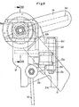
- the actuating device - see initially FIG. 4 - for the aforementioned rotation of the swivel body 3 and the movement of the shafts 4a of each portal is mounted on the corresponding end wall of the freight wagon and is configured as follows:
- Wa Gense i te forth For convenient access from each Wa Gense i te forth are two, with handwheel or crank 6a provided operation shafts 6 (see also Fig. 14) via plug-in connectors 6b independently of one another with a bottom, the direction of force deflecting transmission 7, here a bevel gear 7, connectable.
- a drive shaft 8 is used to connect an upper worm gear 9 to the lower bevel gear 7.
- the worm gear 9 carries on the output side a rotary lever 9a, the ends of which each hold a handlebar 10, preferably by means of a ball head.
- a further bevel gear 7a is provided according to FIG. 15, which cooperates with the respective handlebar 10 via a threaded spindle 7b with nut 7c.
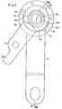
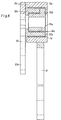
- each handlebar rod 10 is operatively connected to a pivot lever, which is formed from an arm lever 11 and an adjusting lever 12 and is shown as an individual part in FIGS. 5 and 6.
- the articulation lever 11 is rotatable about a fixed point 13 on the end wall and is supported in a region facing away from the fixed point 13 against a guide bar 25 fastened on the end wall (see FIG. 7).
- the articulation lever 11 has a bush-like head 11a which has a stop surface 11 for the adjusting lever 12 which delimits a recess in this head 11a, as a result of which a first coupling which limits the angle of rotation of the adjusting lever 12 is formed.
- the bush-like head 11a of the articulation lever 11 receives a likewise bush-like body 12a of the adjusting lever 12 with the interposition of a sliding bush 14.
- a second coupling there is an arcuate projection 12b on the socket-like body 12a of the adjusting lever 12, in the circular path of which a projection 15b in the form of a segment of a driver bush 15a protrudes.
- the driver bush 15a is mounted via a further inner slide bush 14a in the bush-like body 12a of the adjusting lever 12 and is connected in a rotationally fixed manner via a feather key to the one end of a driver 15, shown in particular in FIG.
- a connecting lever 19 is articulated on the articulation lever 11 of each pivoting lever in view of the pivoting out and inward pivoting of the associated sliding wall part 1, which actuates a lifting rod 21 via a rigid angle lever 20.
- the lifting rod 21 engages an arm 4c attached to the end wall on the shaft 4a for rotating this shaft 4a.
- the actuating device works in the following way: The movement initiated to open a portal with one of the operating shafts 6 passes through bevel gear 7, drive shaft 8, worm gear 9, rotary lever 9a and the handlebars 10 to the adjusting levers 12 of the two swivel levers, which in the direction of the Link lever 11 are pressed.
- the respective adjusting lever 12 rotates within the bush-like head 11a of the articulation lever 11 which initially remains in its position; the arcuate projection 12b of the body 12a on the adjusting lever 12 acts against the segment 15b of the driver bush 15a, so that ultimately the pivot body 3 executes the corresponding rotational movement about its wall-side axis of rotation 3b via the driver 15 connected to this bush 15a.
- the angle of rotation of the adjusting lever 12 is limited by the right abutment surface 11 b on the head 11 a of the articulation lever 11 in the drawing plane of FIG. 5.
- the abovementioned stop surface 11b is arranged such that, when the limitation has taken place, the swivel body 3 has in any case come from its over-dead center position into the closed position in a position which permits the swivel body 3 to be rotated further by swiveling the articulation lever 11 about the fixed point 13 on the end wall.
- the wall-side axis of rotation 3b reaches the outside in an almost straight line and the roof-side axis of rotation Axis 3c also upwards until the swivel body is approximately vertical in a new dead center and subsequently swings into the open position.
- the segment 15b of the driver bush 15a lifts off from one side of the arcuate projection 12b of the body 12a on the adjusting lever 12 and rests against the other side of the projection 12b in the open position.
- the adjusting lever 12 of the swivel lever is again operated first; the driver bush 15a is rotated by the aforementioned interaction of the arcuate projection 12b with the segment 15b in the form of a segment of a circle, and the swivel body is moved approximately into its vertical position about its wall-side axis of rotation 3b.
- the left stop surface 11b in FIG. 5 on the head 11a of the articulation lever 11 limits the angle of rotation of the adjustment lever 12. The closing ends when the articulation lever 11 is pivoted back.
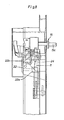
- the adjusting lever 12 is provided with a support plate 12c which receives a bolt 12e for a swivel piece 12f in bearing eyes 12d.
- the handlebar rod 10 of the drive engages a swivel fork 12g of the swivel piece 12f.
- a lock 16 mounted on the support plate 12c of the adjusting lever 12 ensures that the pivot piece 12f cannot initially rotate about the bolt 12e.
- a driving fork 12h of the swivel piece 12f is used for the rotatable fastening - for this purpose screws 17 and sleeves 17a - of a bearing bush 15d, which holds the end facing away from the flat 15c of the driving member 15.
- the driver 15 is here connected in a rotationally fixed manner to the driver bush 15a via a shaft 15e which is square in cross section.
- the portal is opened in the manner already described, i.e. by turning the adjusting lever 12, here with the support plate 12c, and moving the articulation lever 11 around the fixed point 13 on the end wall.
- the lock 16 runs against a web 18 shortly before the articulation lever 11 reaches the end position on the end wall (see Fig. 7) and ultimately releases the pivot piece 12f.
- the swivel piece 12f is rotated about the bolt 12e until the sleeves 17a in the driving fork 12h of the swivel piece 12f have passed through the curved path 12j located in this fork 12h (see FIG. 11).
- the flattened portion 15c of the driver 15 is pulled out of the swivel body and brought into a position that lies outside the run-up level of the retracted portal.
- the insertion of the driver 15 into the swivel body 3 is accordingly reversed and before the explained closing of the portal.
- a securing body 22 is shown in the operative position with the longitudinally displaced portal, which locks the adjusting lever 12 in this position of the portal.
- this securing body 22 is rotatably mounted on a bracket 23 of the end wall and moves automatically through a counterweight 22a when the portal is moved longitudinally to open it; a web 22b of the securing body 22 then engages behind a nose 12k which, according to FIG. 5, is located directly on the adjusting lever 12 and according to FIGS. 7 and 9 on its supporting plate 12c.
- the portal guides the securing body 22 back against the force of the counterweight 22b into the starting position, not shown, via a trigger 3d shown in FIG. 1, which is fastened to the folding bracket 3a.
- a further safety lever 24 shown in FIG. 8 ensures, independently of the safety body 22, that the adjusting lever 12 can only be moved back when the driver 15 has positively engaged in the swivel body 3.
- This safety lever 124 is also mounted on the end wall outside its center of gravity, is tilted when the articulation lever 11 is moved into the open position via an inclined surface 121 on the support plate 12c of the adjusting lever 12 (see FIG. 11) and finally snaps behind one at the end of the inclined surface 121 on the support plate 12c
- Adjusting lever 12 (see FIG. 11) is tilted and finally snaps behind a cam 12m located at the end of inclined surface 121.
- a mandrel 12 attached to the swivel piece 12f of the adjusting lever 12 guides the safety lever 24 back into its initial position when the positive connection between the driver 15 and the swivel body 3 is formed and then enables the closing process.
- FIGS. 15 and 16 forms in particular a guide for the roof shell 2 during its lifting movements.
- the roof shell 2 is provided with a fork-like receptacle 2b for a guide body 26 located on the end wall 29, which is mounted so as to be vertically movable via rollers 28 which are rotatably fastened there and have a concave design on their outer surface.
- the guide body 26 has an end profile 26a which bears against the top of the receptacle 2b on the roof shell 2. As a result, a holder for the closed roof shell 2 is formed.
- the bevels 2c of the receptacle 2b shown in FIG. 16, together with the guide body 26, position the roof shell 2 in particular when the portal is pushed shut.
Landscapes
- Engineering & Computer Science (AREA)
- Mechanical Engineering (AREA)
- Transportation (AREA)
- Fittings On The Vehicle Exterior For Carrying Loads, And Devices For Holding Or Mounting Articles (AREA)
Description
Die Erfindung betrifft ein Fahrzeug oder einen Behälter, insbesondere einen Eisenbahngüterwagen, bei dem zwei in Querrichtung gegenüberliegende Schiebewandteile jeweils unten in Führungen schwenk- und längsverschiebbar gehalten und oben über jeweils einen Schwenkkörper mit einer sich in Länge dieser Wandteile erstreckenden Dachschale gelenkig verbunden sind, wobei die Dachschale und die Schiebewandteile durch Drehen der Schwenkkörper mittels einer Betätigungseinrichtung Hub- bzw. Schwenkbewegungen im oberen Bereich ausführen.The invention relates to a vehicle or a container, in particular a railway freight wagon, in which two sliding wall parts opposite each other in the transverse direction are each held at the bottom in guides in a pivotable and longitudinally displaceable manner and are articulated at the top via a swivel body with a roof shell extending in the length of these wall parts, the Carry out lifting and swiveling movements in the upper area by rotating the swivel body using an actuator.
Ein Fahrzeug oder ein Behälter mit den vorgenannten Merkmalen ist in der unter der Nummer 0011 195 veröffentlichten europäischen Patentanmeldung beschrieben und wird als Stand der Technik zugrunde gelegt.A vehicle or a container with the aforementioned features is described in the European patent application published under number 0011 195 and is taken as the basis for the prior art.
Der Erfindung liegt die Aufgabe zugrunde, für ein Fahrzeug oder einen Behälter der gattungsgemäßen Art eine möglichst einfach und Kompakt gestaltete, antriebsseitig mit kurzen Wegen und abtriebsseitig unter eingeschränkten Raumverhältnissen arbeitende Betätigungseinrichtung zu schaffen.The invention has for its object to provide for a vehicle or a container of the generic type as simple and compact as possible, on the drive side with short paths and on the output side operating under limited space.
Diese Aufgabe wird erfindungsgemäß dadurch gelöst, daß die Betätigungseinrichtung für jeden Schwenkkörper einen aus einem Anlenkhebel und einem Verstellhebel gebildeten Schwenkhebel aufweist, von denen der Anlenkhebel um einen fahrzeugseitigen Festpunkt schwenkbar gelagert und der Verstellhebel mit einem Zug-und Druckkräfte liefernden Antrieb verbunden sind, wobei der Anlenkhebel und der Verstellhebel an ihren von dem Festpunkt bzw. von dem Angriffspunkt des Antriebes abgewandten Enden unter Anordnung einer den Drehwinkel des Verstellhebels begrenzenden ersten Kupplung drehbar miteinander verbunden sind und zwischen dem Verstellhebel und einem formschlüssig in den Schwenkkörper eingreifenden Mitnehmer eine mit einem Freiwinkel für Drehbewegungen des Mitnehmers ausgebildete zweite Kupplung angeordnet ist.This object is achieved in that the actuating device for each swivel body has a pivot lever formed from a pivot lever and an adjusting lever, of which the pivot lever is pivotally mounted about a fixed point on the vehicle and the adjusting lever is connected to a drive and pulling force supply drive, the Linkage lever and the adjusting lever at their ends facing away from the fixed point or from the point of application of the drive are rotatably connected to one another by arranging a first coupling which limits the angle of rotation of the adjusting lever and between the adjusting lever and a driver which engages in a form-fitting manner in the swivel body, one with a clearance angle for rotary movements the driver formed second clutch is arranged.
Im Hinblick auf eine räumlich besonders gedrängte Ausführung der beiden Kupplungen ist nach einer Ausgestaltung gemäß der Erfindung vorgesehen, daß - zum Bilden der ersten Kupplung - der Anienkhebel mit einem buchsenartigen Kopf zur drehbaren Aufnahme eines buchsenartigen Körpers des Verstellhebels versehen ist, wobei der buchsenartige Kopf des Anlenkhebels Anschlagflächen für das Begrenzen des Drehwinkels des Verstellhebels aufweist, und daß - zum Bilden der zweiten Kupplung - in die Kreisbahn eines am buchsenartigen Körper des Verstellhebels gebildeten bogenförmigen Vorsprungs ein kreissegmentförmiger Ansatz einer winketsteif am Mitnehmer befestigten Mitnehmerbuchse hineinragt.With regard to a spatially particularly compact design of the two clutches is provided according to an embodiment according to the invention that - to form the first clutch - the Anienkhebel is provided with a socket-like head for rotatably receiving a socket-like body of the adjusting lever, the socket-like head of the Hinged lever has stop surfaces for limiting the angle of rotation of the adjusting lever, and that - to form the second coupling - a circular segment-shaped approach of an angularly rigid driver sleeve protrudes into the circular path of an arcuate projection formed on the sleeve-like body of the adjusting lever.
Nach einer weiteren Ausgestaltung der Erfindung ist der Mitnehmer zum Trennen bzw. zum Erstellen des formschlüssigen Eingriffes in den Schwenkkörper in Längsrichtung bewegbar mit dem Verstellhebel verbunden. Dieser Ausgestaltung liegt folgende Überlegung zugrunde :According to a further embodiment of the invention, the driver is connected to the adjusting lever so as to be movable in the longitudinal direction in order to separate or create the positive engagement in the swivel body. This configuration is based on the following consideration:
Die formschlüssige Verbindung zwischen einem starr angeordneten Mitnehmer und dem Schwenkkörper wird durch Längsverschieben der ausgeschwenkten Schiebewandteile mit derangehobenen Dachschale zum Öffnen oder Schließen, beispielsweise des Güterwagens, zwangsläufig getrennt bzw. erstellt. Insbesondere beim Zuschieben können gegebenenfalls stoßartige Kräfte auf den Mitnehmer und den nachgeschalteten Verstellhebel wirken. Die oben genannte längsbewegbare Verbindung des Mitnehmers mit dem Verstellhebel erlaubt es vorteilhaft, den besagten formschlüssigen Eingriff bei ruhenden Schiebewandteilen mit Dachschale zu trennen und zu erstellen und dadurch solche stoßartigen Kräfte zu vermeiden.The positive connection between a rigidly arranged driver and the swivel body is inevitably separated or created by longitudinally displacing the swung-out sliding wall parts with the raised roof shell for opening or closing, for example the freight wagon. In particular, when pushing shut, sudden forces may act on the driver and the downstream adjusting lever. The above-mentioned longitudinally movable connection of the driver to the adjusting lever advantageously allows said positive engagement to be separated and created when the sliding wall parts are at rest with the roof shell, thereby avoiding such abrupt forces.
Um den Zug- und Druckkräfte liefernden Antrieb in baulich einfacher und für die Bedienung bequemer Weise für das Längsbewegen des Mitnehmers zu nutzen, besteht eine ergänzende Ausbildung gemäß der Erfindung darin, daß der Antrieb mit einem nach Art eines Scharnieres am Verstellhebel angelenkten und am Mitnehmer angreifenden Schwenkstück verbunden ist, wobei eine ebenfalls am Verstellhebel gelagerte Sperre in ihrer verriegelten Stellung das Schwenkstück mit dem Verstellhebel vereinigt und in ihrer gelösten Stellung ein Schwenken des Schwenkstückes im Sinne der Längsbewegungen des Mitnehmers zuläßt.In order to use the drive and compressive forces supplying the drive in a structurally simple and convenient manner for the longitudinal movement of the driver, a supplementary embodiment according to the invention is that the drive is articulated with a hinge on the adjusting lever and engages the driver Swivel piece is connected, wherein a lock also mounted on the adjusting lever in its locked position unites the swivel piece with the adjusting lever and in its released position allows the swivel piece to pivot in the sense of the longitudinal movements of the driver.
Für ein selbsttätiges Lösen der vorgenannten Sperre sieht ein zusätzliches Merkmal nach der Erfindung vor, daß die Sperre gegen einen ortsfesten Steg kurz vor Erreichen der zur Offenstellung der Dachschale und der Schiebewandteile gehörenden Endlage des Anlenkhebels anläuft.For an automatic release of the above-mentioned lock, an additional feature according to the invention provides that the lock runs against a stationary web shortly before reaching the end position of the articulation lever belonging to the open position of the roof shell and the sliding wall parts.
Um eine Fehlbedienung der Betätigungseinrichtung zu verhindern, besteht eine weitere Ausführungsform der Erfindung darin, daß der Verstellhebel bei außerhalb des Eingriffes in den Schwenkkörper stehendem Mitnehmer durch einen stirnwandseitig angelenkten, unter Einführen des Mitnehmers in den Schwenkkörper lösbaren Sicherungshebel arretiert ist.In order to prevent incorrect operation of the actuating device, a further embodiment of the invention consists in that the adjusting lever is locked when the driver is out of engagement in the swivel body by a locking lever which is articulated on the end wall and can be released by inserting the driver into the swivel body.
Für den gleichen Zweck wie vorbezeichnet ist in weiterer Ausgestaltung gemäß der Erfindung ein stirnwandseitig gelagerter Sicherungskörper vorgesehen, der den Verstellhebel hintergreift, sobald die Schiebewandteile mit Dachschale in Richtung auf die Offenstellung geschoben werden, und durch Zurückschieben der Schiebewandteile mit Dachschale in die Schließstellung seine das Bewegen des Verstellhebels zulassende Ausgangslage aufweist.For the same purpose as described above, in a further embodiment according to the invention, a securing body mounted on the end wall is provided, which engages behind the adjusting lever as soon as the sliding wall parts with the roof shell are pushed in the direction of the open position, and by moving the sliding wall parts with the roof shell back into the closed position of the adjusting lever has the starting position.
Im Hinblick auf eine weitestgehende Vereinfachung der Betätigungseinrichtung liegt es ferner im Wesen der Erfindung, daß an dem um den Festpunkt drehbaren Anlenkhebel eine mit unteren Führungselementen zum Aus- und Einschwenken des Schiebewandteiles verbundene Hebelanordnung angelenkt ist.With a view to the greatest possible simplification of the actuating device, it is also in the essence of the invention that at the pivotable about the fixed point one with below Ren guide elements for pivoting the pivoting wall part connected lever arrangement is articulated.
Insbesondere für einen bequemen Zugriff an die Betätigungseinrichtung ist gemäß einer nächsten Ausgestaltung der Erfindung vorgesehen, daß der für die jeweils aus dem Anlenkhebel und dem Verstellhebel gebildeten Schwenkhebel gemeinsame Antrieb von beiden Fahrzeug- oder Behälterlängsseiten aus unabhängig voneinander betätigbare Bedienungsmittel, z. B. Kurbeln, aufweist.In particular, for easy access to the actuating device is provided according to a next embodiment of the invention that the common for the pivot lever formed from the pivot lever and the adjusting lever drive from both sides of the vehicle or container from independently operable operating means, for. B. cranks.
Um in einfacher Weise eine besonders stabile Lagerung des Anlenkhebels zu erzielen, besteht ein weiterer Gedanke gemäß der Erfindung darin, daß der um den Festpunkt drehbare Anlenkhebel in seinem von diesem Festpunkt abgewandten Bereich gegen eine stirnwandseitig befestigte Führungsleiste in Querrichtung beweglich abgestützt ist.In order to achieve a particularly stable mounting of the articulation lever in a simple manner, a further idea according to the invention is that the articulation lever which is rotatable about the fixed point is movably supported in the region facing away from this fixed point against a guide bar fastened to the end wall in the transverse direction.
Um die Dachschale bei deren Hubbewegungen zwangsläufig zu führen, sieht eine nächste Ausführungsform nach der Erfindung vor, daß die Dachschale eine gabelartige Aufnahme für einen stirnwandseitig in der Vertikalen beweglich gelagerten, über den die Zug- und Druckkräfte liefernden Antrieb heb- und senkbaren Führungskörper aufweist. Das hierbei in einfacher Weise mittels der Betätigungseinrichtung vorgesehene Heben und Senken des Führungskörpers erbringt den Vorteil, daß ein für Schienenfahrzeuge geltendes Umgrenzungsprofil bei geschlossenem Portal eingehalten wird.In order to inevitably guide the roof shell during its lifting movements, a next embodiment according to the invention provides that the roof shell has a fork-like receptacle for a vertically movably mounted end wall on the end wall side, via which the pulling and compressive force drive can be raised and lowered guide body. The lifting and lowering of the guide body provided in a simple manner by means of the actuating device provides the advantage that a boundary profile that is valid for rail vehicles is maintained when the portal is closed.
Nach einer weiteren Ausgestaltung der Erfindung ist es gegeben, daß der Führungskörper über eine Hebelgruppe mit einer angetriebenen, am Verstellhebel angreifenden Lenkerstange verbunden ist.According to a further embodiment of the invention, it is provided that the guide body is connected via a lever group to a driven handlebar which acts on the adjusting lever.
Um die Betätigungseinrichtung auch als Halterung für die geschlossene Dachschale, die an sich schon durch ihr Gewicht einem ungewollten Anheben im Fahrbetrieb entgegenwirkt, verwenden zu können, weist in erfindungsgemäßer Weiterbildung der Führungskörper ein gegen die Oberseite der Aufnahme an der Dachschale anliegendes Abschlußprofil auf.In order to be able to use the actuating device also as a holder for the closed roof shell, which itself counteracts unwanted lifting during driving due to its weight, in a further development according to the invention the guide body has a closing profile which bears against the top of the receptacle on the roof shell.
Im Hinblick auf eine einfache Positionierung insbesondere der Dachschale beim Zuschieben des Portales besteht ein ergänzendes Merkmal nach der Erfindung darin, daß die Aufnahme an der Dachschale zur Quermitte des Fahrzeuges oder des Behälters hin konvergierende Anlaufflächen für den Führungskörper aufweist. Dadurch wird ein exaktes, stoßfreies Zusammenfügen der Schwenkkörper und der Mitnehmer erzielt.With regard to a simple positioning, in particular of the roof shell when the portal is pushed shut, a supplementary feature according to the invention is that the receptacle on the roof shell has converging contact surfaces for the guide body towards the transverse center of the vehicle or the container. This results in an exact, bumpless joining of the swivel body and the driver.
In dem Bestreben, den Kraftaufwand für die Betätigung so klein wie möglich zu halten, wird eine dazu dienliche leichtgängige Lagerung des Führungskörpers nach einer weiteren Ausgestaltung der Erfindung dadurch erreicht, daß der Führungskörper als Rohr ausgebildet und über stirnwandseitig drehbar befestigte, an ihrer Mantelfläche konkav gestaltete Rollen gelagert ist.In an effort to keep the effort required for actuation as small as possible, a convenient, smooth bearing of the guide body according to a further embodiment of the invention is achieved in that the guide body is designed as a tube and is designed to be concave on its outer surface by means of a rotatable end wall Rolls is stored.
Die mit dem Gegenstand nach der Erfindung erzielbaren Vorteile bestehen insbesondere darin, daß die Betätigungseinrichtung einfach und kompakt gestaltet ist, was auch ihrer Unterbringung am Fahrzeug oder am Behälter und ihrer Funktionssicherheit zugute kommt, wobei eine, volle Hub- bzw. Schwenkbewegungen der Dachschale und der Schiebewandteile ergebende Drehung der Schwenkkörper um annähernd 180° durch Bewegen der jeweils aus dem Verstellhebel und dem Anlenkhebel gebildeten Schwenkhebel lediglich innerhalb eines vergleichsweise kleinen Schwenkwinkels erzeugt wird.The advantages that can be achieved with the object according to the invention consist in particular in that the actuating device is simple and compact, which also benefits its placement on the vehicle or on the container and its functional reliability, with a full lifting or swiveling movement of the roof shell and the Sliding wall parts resulting rotation of the pivot body by approximately 180 ° is generated only by moving the pivot lever formed from the adjusting lever and the link lever within a comparatively small pivot angle.
Ausführungsbeispiele der Erfindung sind in der Zeichnung dargestellt und werden im folgenden näher beschrieben. Es zeigen
Figur 1 den prinzipartigen Querschnitt eines Güterwagens,Figur 2 die Einzelheit Z aus Fig. 1, im vergrößerten Maßstab,Figur 3 die Einzelheit Y aus Fig. 1, ebenfalls vergrößert,Figur 4 die vereinfachte Ansicht gegen die Stirnwand des Güterwagens nach Fig. 1 mit Betätigungseinrichtung,- Figur 5 den in Fig. 4 rechts oben dargestellten, aus dem
Anlenkhebel 11 und demVerstellhebel 12 gebildeten Schwenkhebel als Einzelteil, Figur 6 den Schnitt nach der Linie VI-VI in Fig. 5,Figur 7 die Betätigungseinrichtung im oberen Bereich entsprechend Fig. 4, jedoch mit einem weitergestalteten Schwenkhebel,Figur 8 die Ansicht in Pfeilrichtung X in Fig. 7,Figur 9 den Schwenkhebel gemäß Fig. 7 in Ansicht, im vergrößerten Maßstab,Figur 10 die Seitenansicht des Schwenkhebels nach Fig.9,Figur 11 die Draufsicht des Schwenkhebels nach Fig. 9,Figur 12 den Schnitt nach der Linie XII-XII in Fig. 9,Figur 13 den Schnitt nach der Linie XIII-XIII in Fig. 12,Figur 14 die Betätigungseinrichtung im Schnitt nach der Linie XIV-XIV in Fig. 4,Figur 15 eine weitere Ansicht gegen einen Bereich der Stirnwand des Güterwagens nach Fig.1,Figur 16 die vereinfachte Draufsicht zu Fig. 15.
- FIG. 1 shows the principle cross section of a freight car,
- FIG. 2 shows the detail Z from FIG. 1, on an enlarged scale,
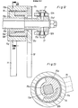
- 3 shows detail Y from FIG. 1, likewise enlarged,
- FIG. 4 shows the simplified view against the front wall of the freight wagon according to FIG. 1 with the actuating device,
- 5 shows the pivot lever shown in FIG. 4 at the top right, formed from the
articulation lever 11 and the adjustinglever 12, as an individual part, - 6 shows the section along the line VI-VI in FIG. 5,
- FIG. 7 shows the actuating device in the upper area corresponding to FIG. 4, but with a swivel lever that has been further developed,
- 8 shows the view in the direction of arrow X in FIG. 7,
- FIG. 9 shows the swivel lever according to FIG. 7 in view, on an enlarged scale,
- FIG. 10 shows the side view of the swivel lever according to FIG. 9,
- FIG. 11 shows the top view of the pivoting lever according to FIG. 9,
- FIG. 12 shows the section along the line XII-XII in FIG. 9,
- FIG. 13 the section along the line XIII-XIII in FIG. 12,
- FIG. 14 the actuating device in section along the line XIV-XIV in FIG. 4,
- FIG. 15 shows a further view against a region of the end wall of the freight wagon according to FIG. 1,
- FIG. 16 shows the simplified top view of FIG. 15.
Bei dem Güterwagen nach vorliegendem Ausführungsbeispiel bestehen die Seitenwände aus jeweils zwei Schiebewandteilen 1. Das Wagendach wird durch zwei Dachschalen 2 gebildet, von denen jede sich in Länge eines Schiebewandteiles 1 erstreckt und mit den in Wagenquerrichtung gegenüberliegenden Wandteilen 1 über Schwenkkörper 3 gelenkig verbunden ist. Die beiden so gebildeten Portale sind durch Drehen der zugehörigen Schwenkkörper um fast 180° und im Raum - siehe insbesondere Fig. 2 - sowie durch gemeinsames Bewegen der nachstehend beschriebenen unteren Führungselemente 4 (siehe Fig.3) in eine Offenstellung führbar, die ein Längsverschieben des entsprechenden Portales über das andere, in Schließstellung befindliche Portal zuläßt.In the freight car according to the present exemplary embodiment, the side walls each consist of two sliding
Die unteren Führungselemente 4 enthalten gemäß Fig.3 eine Welle 4a mit daran angebrachten Schwenkarmen 4b, die jeweils in eine Lagerung von mit Rollen 1b versehenen Laufwagen 1a am Schiebewandteil 1 eingreifen. Das Schiebewandteil 1 ist in der Schließstellung über einen Steg 1 c an seinen Laufwagen 1a an einem Langträger5a des Wagenuntergestelles 5 abgestützt und - nach erfolgtem Bewegen der Welle 4a - in der Offenstellung auf einer vor der Welle 4a liegenden Laufschiene 5b am Untergestell 5 längsverchiebbar gehalten.According to FIG. 3, the
Im übrigen ist jedes Portal gemäß Fig. 2 in der Schließstellung durch Übertotpunktlage der Schwenkkörper3, also unter Verzicht auf sonst erforderliche Verriegelungen, gehalten. In der Offenstellung des Portales liegen unter dem Gewicht der Dachschale 2 gegen den jeweiligen Schwenkkörper 3 ein Flansch 2a dieser Schale 2 und ein Flansch 1d des Schiebewandteiles 1 im Sinne einer Stabilisierung an, wobei als zusätzliche Sicherung gegen ein Bewegen der geöffneten Schiebewandteile 1 in Richtung auf die Wagenlängsmitte jeweils am stirnwandseitigen Ende des Schwenkkörpers 3 ein Klappbügel 3a gelagert ist, der gegen eine Nase 1e am Schiebewandteil 1 wirkt.Moreover, each portal according to FIG. 2 is held in the closed position by the
Die Betätigungseinrichtung - siehe zunächst Fig. 4 - für das genannte Drehen der Schwenkkörper 3 und das Bewegen der Wellen 4a jedes Portales ist an der entsprechenden Stirnwand des Güterwagens gelagert und wie folgt ausgestaltet :The actuating device - see initially FIG. 4 - for the aforementioned rotation of the
Für einen bequemen Zugriff von jeder Wa- genseite her sind zwei, mit Handrad oder Kurbel 6a versehene Bedienungswellen 6 (siehe auch Fig. 14) über Steckkupplungen 6b unabhängig voneinander mit einem unteren, die Kraftrichtung umlenkenden Getriebe 7, hier einem Kegelradgetriebe 7, verbindbar. Eine Antriebswelle8 dient dem Anschluß eines oberen Schneckengetriebes 9 an das untere Kegelradgetriebe 7.For convenient access from each Wa Gense i te forth are two, with handwheel or crank 6a provided operation shafts 6 (see also Fig. 14) via plug-in
Wie aus Fig. 4 weiter ersichtlich, trägt das Schneckengetriebe 9 abtriebseitig einen Drehhebel9a, dessen Enden jeweils eine Lenkerstange 10, bevorzugt mittels eines Kugelkopfes, aufnehmen. Alternativ zu Schneckengetriebe 9 und Drehhebel 9a ist gemäß Fig. 15 ein weiteres Kegelradgetriebe 7a vorgesehen, das der jeweiligen Lenkerstange 10 über eine Gewindespindel 7b mit Mutter 7c zusammenarbeitet.As can also be seen from FIG. 4, the
Das freie Ende jeder Lenkerstange 10 steht mit einem Schwenkhebel in Wirkverbindung, der aus einem Anienkhebel 11 und einem Verstellhebel 12 gebildet und in den Fig. 5 und 6 als Einzelteil gezeigt ist. Der Anlenkhebel11 ist um einen stirnwandseitigen Festpunkt 13 drehbar und in einem vom Festpunkt 13 abgewandten Bereich gegen eine stirnwandseitig befestigte Führungsleiste 25 (siehe Fig. 7) abgestützt. Der Anlenkhebel11 hat einen buchsenartigen Kopf 11a, der eine Ausnehmung in diesem Kopf 11a begrenzende Anschlagflächen 11 für den Verstellhebel 12 aufweist, wodurch eine den Drehwinkel des Verstellhebel 12 begrenzende erste Kupplung gebildet wird. Der buchsenartige Kopf 11a des Anlenkhebels 11 nimmt einen ebenfalls buchsenartigen Körper 12a des Verstellhebels 12 unter Zwischenschaltung einer Gleitbuchse 14 auf. Zum Bilden einer zweiten Kupplung besteht an dem buchsenartigen Körper 12a des Verstellhebels 12 ein bogenförmiger Vorspruch 12b, in dessen Kreisbahn ein kreissegmentförmiger Ansatz 15b einer Mitnehmerbuchse 15a hineinragt. Die Mitnehmerbuchse 15a ist über eine weitere, innere Gleitbuchse 14a im buchsenartigen Körper 12a des Verstellhebels 12 gelagert und über eine Paßfeder drehfest mit dem einen Ende eines insbesondere in Fig. 11 vollständig gezeigten Mitnehmers 15 verbunden, dessen anderes Ende eine formschlüssig in den Schwenkkörper 3 eingreifende Anflächung 15c hat. Im übrigen sichert ein am buchsenartigen Kopf 11a des Anlenkhebels 11 angeschraubtes Abdeckblech 11 die in diesem Kopf 11a angeordneten Teile gegen Herausfallen.The free end of each
Wie aus Fig. 4 oder 7 weiter ersichtlich, ist an dem Anlenkhebel 11 jedes Schwenkhebels im Hinblick auf das Aus- und Einschwenken des zugehörigen Schiebewandteiles 1 im unteren Bereich ein Verbindungshebel 19 angelenkt, der über einen starren Winkelhebel 20 eine Hubstange 21 betätigt. Die Hubstange 21 greift an einem stirnwandseitig an der Welle 4a befestigten Arm 4c zum Drehen dieser Welle 4a an.As can also be seen from FIG. 4 or 7, a connecting
Die Betätigungseinrichtung arbeitet in folgender Weise : Die zum Öffnen eines Portales mit einer der Bedienungswellen 6 eingeleitete Bewegung gelangt über Kegelradgetriebe 7, Antriebswelle 8, Schneckengetriebe 9, Drehhebel 9a und die Lenkerstangen 10 zu den Verstellhebeln 12 der beiden Schwenkhebel, die dabei in Richtung auf die Anlenkhebel 11 gedrückt werden. Der jeweilige Verstellhebel 12 dreht sich innerhalb des buchsenartigen Kopfes 11a des zunächst in seiner Stellung bleibenden Anlenkhebels 11 ; dabei wirkt der bogenförmige Vorsprung 12b des Körpers 12a am Verstellhebel 12 gegen den kreissegmentförmigen Ansatz 15b der Mitnehmerbuchse 15a, so daß über den mit dieser Buchse 15a verbundenen Mitnehmer 15 letztlich der Schwenkkörper3 die entsprechende Drehbewegung um seine wandseitige Drehachse 3b ausführt. Der Drehwinkel des Verstellhebels 12 wird durch die in Zeichnungsebene der Fig. 5 rechte Anschlagfläche 11 b am Kopf 11 a des Anlenkhebels 11 begrenzt. Die vorgenannte Anschlagfläche 11 b ist so angeordnet, daß, bei erfolgter Begrenzung, der Schwenkkörper3 jedenfalls aus seiner Übertotpunktlage in Schließstellung in eine Lage gekommen ist, die ein weiteres Drehen des Schwenkkörpers 3 durch Schwenken des Anlenkhebels 11 um den stirnwandseitigen Festpunkt 13 zuläßt. Dabei gelangen die wandseitige Drehachse 3b annähernd geradlinig nach außen und die dachseitige Drehachse 3c ebenso nach oben, bis der Schwenkkörper etwa senkrecht in einem erneuten Totpunkt steht und nachfolgend in die Offenstellung schwingt.The actuating device works in the following way: The movement initiated to open a portal with one of the
Auf dem Weg des Schwenkkörpers 3 in die Offenstellung hebt der kreissegmentförmige Ansatz 15b der Mitnehmerbuchse 15a von der einen Seite des bogenförmigen Vorsprunges 12b des Körpers 12a am Verstellhebel 12 ab und liegt bei Offenstellung gegen die andere Seite des Vorsprunges 12b an. Zum Schließen des Portales wird wiederum zuerst der Verstellhebel 12 des Schwenkhebels betätigt ; dabei wird über das zuvor genannte Zusammenwirken des bogenförmigen Vorsprunges 12b mit dem kreissegmentförmigen Ansatz 15b die Mitnehmerbuchse 15a gedreht und der Schwenkkörper um seine wandseitige Drehachse 3b etwa in die Vertikalstellung bewegt. Die in Fig. 5 linke Anschlagfläche 11b am Kopf 11a des Anlenkhebels 11 begrenzt den Drehwinkel des Verstellhebels 12. Das Schließen endet mit dem Zurückschwenken des Anlenkhebels 11.On the way of the
Beim Längsverschieben eines Portales zum Be-oder Entladen des Güterwagens wird die formschlüssige Verbindung zwischen dem jeweiligen Schwenkkörper3 und der Anflächung 15c des Mitnehmers 15 aufgehoben. Beim Zuschieben des Portales bildet sich diese Verbindung wieder, wobei eine maulförmige Erweiterung des Schwenkkörpers 3 einen im Rahmen der zugelassenen Fertigungstoleranz liegenden Versatz ausgleicht. Um den Schwenkkörper und den Mitnehmer 15 auf jeden Fall von dynamischen Kräften freizuhalten, die beim vorgenannten Bilden der formschlüssigen Verbindung auftreten können, ist der Mitnehmer 15 bei dem Schwenkhebel gemäß den Fig. bis 13 in Längsrichtung beweglich. Diesem Schwenkhebel liegt der Aufbau nach den Fig. und 6 zugrunde. Ergänzend dazu ist der Verstellhebel 12 mit einem Tragblech 12c versehen, das in Lageraugen 12d einen Bolzen 12e für ein Schwenkstück 12f aufnimmt. Die Lenkerstange 10 des Antriebes greift an einer Schwenkgabel 12g des Schwenkstückes 12f an. Eine am Tragblech 12c des Verstellhebels 12 gelagerte Sperre 16 sorgt dafür, daß das Schwenkstück 12f zunächst keine Drehung um den Bolzen 12e ausführen kann. Eine Mitnehmergabel 12h des Schwenkstückes 12f dient der drehbaren Befestigung - dazu Schrauben 17 und Hülsen 17a - einer Lagerbuchse 15d, die das von der Anflächung 15c des Mitnehmers 15 abgewandte Ende hält. Der Mitnehmer 15 ist hier über einen im Querschnitt quadratischen Schaft 15e drehfest mit der Mitmehmerbuchse 15a verbunden. Das Öffnen des Portales erfolgt in der bereits beschriebenen Weise, also durch Drehen des Verstellhebels 12, hier mit Tragblech 12c, und Bewegen des Anlenkhebels 11 um den stirnwandseitigen Festpunkt 13. Die Sperre 16 läuft kurz vor Erreichen der Endstellung des Anlenkhebels 11 gegen einen Steg 18 an der Stirnwand (siehe Fig. 7) und gibt letztlich das Schwenkstück 12f frei. Durch Weiterbetätigen der Kurbel 6a wird das Schwenkstück 12f um den Bolzen 12e gedreht, bis die Hülsen 17a in der Mitnehmergabel 12h des Schwenkstückes 12f die in dieser Gabel 12h befindliche Kurvenbahn 12j (siehe Fig. 11) durchlaufen haben. Die Anflächung 15c des Mitnehmers 15 wird dabei aus dem Schwenkkörper gezogen und in eine Position gebracht, die außerhalb der Auflaufebene des zurückgeschobenen Portales liegt. Das Einführen des Mitnehmers 15 in den Schwenkkörper 3 erfolgt entsprechend umgekehrt und vor dem erläuterten Schließen des Portales.When a portal is moved longitudinally for loading or unloading the freight wagon, the positive connection between the
In den Fig. 7 und 8 ist ein Sicherungskörper 22 in Wirkposition bei längsverschobenem Portal gezeigt, der bei dieser Stellung des Portales den Verstellhebel 12 arretiert. Dafür ist dieser Sicherungskörper 22 an einer Konsole 23 der Stirnwand drehbar gelagert und bewegt sich durch ein Kontergewicht 22a selbsttätig, wenn das Portal zum Öffnen längsverschoben wird ; ein Steg 22b des Sicherungskörpers 22 hintergreift dann eine Nase 12k, die sich gemäß Fig. 5 unmittelbar am Verstellhebel 12 und nach Fig. 7 und 9 an dessen Tragblech 12c befindet. Das Portal führt beim Zuschieben über einen in Fig. dargestellten Auslöser 3d, der an dem Klappbügel 3a befestigt ist, den Sicherungskörper 22 gegen die Kraft des Kontergewichtes 22b in die nicht gezeigte Ausgangsstellung zurück.7 and 8, a securing
Ein weiterer, in Fig. 8 dargestellter Sicherungshebel24 sorgt unabhängig vom Sicherungskörper 22 dafür, daß der Verstellhebel 12 erst zurückbewegt werden kann, wenn der Mitnehmer 15 formschlüssig in den Schwenkkörper3 eingegriffen hat. Dieser Sicherungshebe124 ist außerhalb seines Schwerpunktes ebenfalls stirnwandseitig gelagert, wird beim Bewegen des Anlenkhebels 11 in die Offenstellung über eine Schrägfläche 121 am Tragblech 12c des Verstellhebels 12 (siehe Fig. 11) gekippt und schnappt schließlich hinter einen am Ende der Schrägfläche 121 am Tragblech 12c des Verstellhebels 12 (siehe Fig. 11) gekippt und schnappt schließlich hinter einen am Ende der Schrägfläche 121 befindlichen Nocken 12m. Ein am Schwenkstück 12f des Verstellhebels 12 angebrachter Dorn 12 führt den Sicherungshebel 24 beim Bilden der formschlüssigen Verbindung von Mitnehmer 15 und Schwenkkörper 3 in seine Ausgangslage zurück und ermöglicht dann den Schließvorgang.A
Die in den Fig. 15 und 16 gezeigte Anordnung bildet insbesondere eine Führung für die Dachschale 2 bei deren Hubbewegungen. Dazu ist die Dachschale 2 mit einer gabelartigen Aufnahme 2b für einen an der Stirnwand 29 befindlichen Führungskörper 26 versehen, der über dort drehbar befestigte, an ihrer Mantelfläche konkav gestaltete Rollen 28 vertikal beweglich gelagert ist. Um den Führungskörper 26 auf einfache Weise entsprechend den Hubbewegungen der Dachschale 2 heben oder senken zu können, steht die einerseits an der Mutter7c auf der Gewindespindel 7b des oberen Kegelradgetriebes 7a und andererseits am Verstellhebel 12 angeschlossene Lenkerstange 10 über eine Hebelgruppe 27 mit dem Führungskörper 26 in Wirkverbindung.The arrangement shown in FIGS. 15 and 16 forms in particular a guide for the
Wie aus den Fig. 15 und 16 weiter ersichtlich, weist der Führungskörper 26 ein gegen die Oberseite der Aufnahme 2b an der Dachschale 2 anliegendes Abschlußprofil 26a auf. Dadurch wird eine Halterung für die geschlossene Dachschale 2 gebildet. Außerdem in Fig. 16 gezeigte Anlaufschrägen 2c der Aufnahme 2b erbringen zusammen mit dem Führungskörper 26 beim Zuschieben des Portales eine Positionierung insbesondere der Dachschale 2.As can also be seen from FIGS. 15 and 16, the
Claims (15)
Priority Applications (1)
| Application Number | Priority Date | Filing Date | Title |
|---|---|---|---|
| AT81100600T ATE4634T1 (en) | 1980-02-20 | 1981-01-28 | VEHICLE OR CONTAINER, ESPECIALLY RAILWAY WAGON. |
Applications Claiming Priority (4)
| Application Number | Priority Date | Filing Date | Title |
|---|---|---|---|
| DE19803006371 DE3006371A1 (en) | 1980-02-20 | 1980-02-20 | Railway goods van sides and roof mechanism linked - has swivel lever arms hinged to form locking travelling carrier |
| DE3006371 | 1980-02-20 | ||
| DE3041193 | 1980-11-03 | ||
| DE19803041193 DE3041193A1 (en) | 1980-11-03 | 1980-11-03 | Covered railway goods wagon - has roof and walls in two sections with one section able to slide over other |
Publications (2)
| Publication Number | Publication Date |
|---|---|
| EP0034717A1 EP0034717A1 (en) | 1981-09-02 |
| EP0034717B1 true EP0034717B1 (en) | 1983-09-14 |
Family
ID=25783824
Family Applications (1)
| Application Number | Title | Priority Date | Filing Date |
|---|---|---|---|
| EP81100600A Expired EP0034717B1 (en) | 1980-02-20 | 1981-01-28 | Vehicle or container, particularly a railway goods wagon |
Country Status (4)
| Country | Link |
|---|---|
| EP (1) | EP0034717B1 (en) |
| DD (1) | DD156241A1 (en) |
| DE (1) | DE3160857D1 (en) |
| ES (1) | ES499587A0 (en) |
Families Citing this family (12)
| Publication number | Priority date | Publication date | Assignee | Title |
|---|---|---|---|---|
| DD209601B1 (en) * | 1982-07-14 | 1987-11-04 | Niesky Waggonbau Veb | HOOD COVER FOR CARS |
| GB2154194A (en) * | 1984-02-16 | 1985-09-04 | Ukf Fertilisers Limited | Railcar door openable by fork-lift truck tine |
| GB2154195A (en) * | 1984-02-16 | 1985-09-04 | Ukf Fertilisers Limited | Railcar hinged side door |
| GB2157246B (en) * | 1984-04-10 | 1987-11-25 | Structure Flex Limited | Retractable cover assembly for a load carrying vehicle |
| DD261053A3 (en) * | 1984-07-20 | 1988-10-19 | Niesky Waggonbau Veb | SPREIZHAUBENVERDECK FOR GUETERWAGEN AND CONTAINER |
| DD227100B1 (en) * | 1984-09-20 | 1988-10-19 | Niesky Waggonbau Veb | COVER CAPS FOR CARS AND CONTAINERS |
| GB8628033D0 (en) * | 1986-11-24 | 1986-12-31 | Marmon Holdings Uk Ltd | Railway vehicle |
| DE4140347C2 (en) * | 1991-12-06 | 2001-09-27 | Dwa Deutsche Waggonbau Gmbh | Covered freight car, especially double-decker car transport wagon |
| KR100498128B1 (en) * | 2002-09-17 | 2005-07-01 | 최외수 | Freight car for railroad |
| CN101797925B (en) * | 2010-03-29 | 2012-02-08 | 南车眉山车辆有限公司 | Device for locking movable vehicle roof |
| FR3064579A1 (en) * | 2017-03-30 | 2018-10-05 | Titagarh Wagons Afr | MECHANICAL CONNECTION HAVING A DOUBLE PIVOT CONNECTION AND A RAILWAY VEHICLE COMPRISING SUCH A MECHANICAL CONNECTION |
| CN110667626B (en) * | 2019-10-08 | 2024-09-17 | 中车太原机车车辆有限公司 | Open top cap in long side is led to railway hopper car |
Citations (7)
| Publication number | Priority date | Publication date | Assignee | Title |
|---|---|---|---|---|
| DE923669C (en) * | 1952-02-12 | 1955-02-21 | Franz Kruckenberg Dipl Ing | Closed vehicle body, especially for rail vehicles |
| DE1159990B (en) * | 1960-05-20 | 1963-12-27 | Pierre Jean Marie Theodore All | Goods wagons, especially for the transport of bulk and piece goods |
| FR1451558A (en) * | 1965-07-23 | 1966-01-07 | D Epluches Atel Const | Open-body cargo vehicle |
| DE1580997A1 (en) * | 1966-12-09 | 1971-12-16 | Orenstein & Koppel Ag | Covered wagon |
| DE2133251A1 (en) * | 1970-11-13 | 1972-05-18 | Mini Verkehrswesen | Device for optional lateral pivoting of vehicle roofs |
| DE1605032C3 (en) * | 1966-05-11 | 1975-06-19 | Waggonfabrik Uerdingen Ag, 4150 Krefeld-Uerdingen | Covered freight car with sliding wall parts lying on one level when closed |
| EP0011195A1 (en) * | 1978-11-15 | 1980-05-28 | Duewag Aktiengesellschaft | Car or container, particularly a railway goods wagon |
Family Cites Families (1)
| Publication number | Priority date | Publication date | Assignee | Title |
|---|---|---|---|---|
| US3520257A (en) * | 1967-03-15 | 1970-07-14 | Shunk Mfg Co Inc | Telescopic car covers |
-
1981
- 1981-01-28 EP EP81100600A patent/EP0034717B1/en not_active Expired
- 1981-01-28 DE DE8181100600T patent/DE3160857D1/en not_active Expired
- 1981-02-12 DD DD81227590A patent/DD156241A1/en not_active IP Right Cessation
- 1981-02-19 ES ES499587A patent/ES499587A0/en active Granted
Patent Citations (8)
| Publication number | Priority date | Publication date | Assignee | Title |
|---|---|---|---|---|
| DE923669C (en) * | 1952-02-12 | 1955-02-21 | Franz Kruckenberg Dipl Ing | Closed vehicle body, especially for rail vehicles |
| DE1159990B (en) * | 1960-05-20 | 1963-12-27 | Pierre Jean Marie Theodore All | Goods wagons, especially for the transport of bulk and piece goods |
| FR1451558A (en) * | 1965-07-23 | 1966-01-07 | D Epluches Atel Const | Open-body cargo vehicle |
| BE684499A (en) * | 1965-07-23 | 1967-01-03 | ||
| DE1605032C3 (en) * | 1966-05-11 | 1975-06-19 | Waggonfabrik Uerdingen Ag, 4150 Krefeld-Uerdingen | Covered freight car with sliding wall parts lying on one level when closed |
| DE1580997A1 (en) * | 1966-12-09 | 1971-12-16 | Orenstein & Koppel Ag | Covered wagon |
| DE2133251A1 (en) * | 1970-11-13 | 1972-05-18 | Mini Verkehrswesen | Device for optional lateral pivoting of vehicle roofs |
| EP0011195A1 (en) * | 1978-11-15 | 1980-05-28 | Duewag Aktiengesellschaft | Car or container, particularly a railway goods wagon |
Also Published As
| Publication number | Publication date |
|---|---|
| ES8201079A1 (en) | 1981-12-01 |
| DE3160857D1 (en) | 1983-10-20 |
| DD156241A1 (en) | 1982-08-11 |
| ES499587A0 (en) | 1981-12-01 |
| EP0034717A1 (en) | 1981-09-02 |
Similar Documents
| Publication | Publication Date | Title |
|---|---|---|
| EP0536528B1 (en) | Device for operating a swinging and sliding door for passenger vehicles, especially rail vehicles | |
| EP1621386B1 (en) | Wind stop device | |
| AT501468B1 (en) | Pivotable sliding door, especially for railway vehicles, has a roller lever for engaging into a guide rail on a door leaf and for moving on a curved track | |
| EP1372999B1 (en) | Sliding door guide with carriages and running rails on motor vehicles | |
| DE19735181C2 (en) | Swivel sliding door for vehicles | |
| EP0034717B1 (en) | Vehicle or container, particularly a railway goods wagon | |
| AT500017B1 (en) | SWIVEL SLIDING DOOR FOR VEHICLES | |
| DE69404070T2 (en) | Device that enables a vehicle to carry a load, e.g. a bucket to pick up or put down on the floor and possibly empty it | |
| DE3312001A1 (en) | RAILWAY WAGON | |
| DE102009018188B4 (en) | Device for automatically closing a vehicle door | |
| CH621976A5 (en) | ||
| DE19964066B4 (en) | Locking device for a hood of a vehicle | |
| EP1907231A2 (en) | Drive unit of a movable vehicle component | |
| EP1103403A2 (en) | Adjustable panel in the interior covering of a vehicle | |
| DE10057872A1 (en) | Hardtop vehicle roof | |
| EP0083038A1 (en) | Buffer stop for track systems | |
| DE10132361C1 (en) | Aeroplane passenger door, for accessing passenger cabin, has lifting mechanism for opening passenger door cooperating with lowering safety device | |
| DE60304475T2 (en) | TO FACILITATE THE INTRODUCTION OF OBJECTS UNDER A FOLDING ROOF IN THE LUGGAGE OF A MOTOR VEHICLE | |
| DE102008045903B4 (en) | Motor vehicle with mechanism for moving a flap | |
| EP1017918B1 (en) | Bar-shaped closure, with operating travel moving away from the door leaf | |
| DE3006371A1 (en) | Railway goods van sides and roof mechanism linked - has swivel lever arms hinged to form locking travelling carrier | |
| EP0911199B1 (en) | Pivotable sliding door | |
| DE4402978C2 (en) | Rear seat back for motor vehicles | |
| DE3145871A1 (en) | Trailer coupling device of a lorry | |
| DD156241A2 (en) | VEHICLE OR CONTAINER, ESPECIALLY RAIL CARS |
Legal Events
| Date | Code | Title | Description |
|---|---|---|---|
| PUAI | Public reference made under article 153(3) epc to a published international application that has entered the european phase |
Free format text: ORIGINAL CODE: 0009012 |
|
| 17P | Request for examination filed |
Effective date: 19810209 |
|
| AK | Designated contracting states |
Designated state(s): AT BE CH DE FR GB IT NL SE |
|
| RAP1 | Party data changed (applicant data changed or rights of an application transferred) |
Owner name: DUEWAG AKTIENGESELLSCHAFT |
|
| ITF | It: translation for a ep patent filed | ||
| GRAA | (expected) grant |
Free format text: ORIGINAL CODE: 0009210 |
|
| AK | Designated contracting states |
Designated state(s): AT BE CH DE FR GB IT LI NL SE |
|
| REF | Corresponds to: |
Ref document number: 4634 Country of ref document: AT Date of ref document: 19830915 Kind code of ref document: T |
|
| REF | Corresponds to: |
Ref document number: 3160857 Country of ref document: DE Date of ref document: 19831020 |
|
| PGFP | Annual fee paid to national office [announced via postgrant information from national office to epo] |
Ref country code: SE Payment date: 19831130 Year of fee payment: 4 |
|
| ET | Fr: translation filed | ||
| PGFP | Annual fee paid to national office [announced via postgrant information from national office to epo] |
Ref country code: FR Payment date: 19831216 Year of fee payment: 4 |
|
| PGFP | Annual fee paid to national office [announced via postgrant information from national office to epo] |
Ref country code: CH Payment date: 19840126 Year of fee payment: 4 |
|
| PLBE | No opposition filed within time limit |
Free format text: ORIGINAL CODE: 0009261 |
|
| STAA | Information on the status of an ep patent application or granted ep patent |
Free format text: STATUS: NO OPPOSITION FILED WITHIN TIME LIMIT |
|
| 26N | No opposition filed | ||
| PGFP | Annual fee paid to national office [announced via postgrant information from national office to epo] |
Ref country code: BE Payment date: 19841231 Year of fee payment: 5 |
|
| PGFP | Annual fee paid to national office [announced via postgrant information from national office to epo] |
Ref country code: DE Payment date: 19850104 Year of fee payment: 5 |
|
| PGFP | Annual fee paid to national office [announced via postgrant information from national office to epo] |
Ref country code: AT Payment date: 19860130 Year of fee payment: 6 |
|
| PGFP | Annual fee paid to national office [announced via postgrant information from national office to epo] |
Ref country code: NL Payment date: 19860131 Year of fee payment: 6 |
|
| PG25 | Lapsed in a contracting state [announced via postgrant information from national office to epo] |
Ref country code: AT Effective date: 19870128 |
|
| PG25 | Lapsed in a contracting state [announced via postgrant information from national office to epo] |
Ref country code: SE Effective date: 19870129 |
|
| PG25 | Lapsed in a contracting state [announced via postgrant information from national office to epo] |
Ref country code: LI Effective date: 19870131 Ref country code: CH Effective date: 19870131 |
|
| BERE | Be: lapsed |
Owner name: DUEWAG A.G. Effective date: 19870131 |
|
| PG25 | Lapsed in a contracting state [announced via postgrant information from national office to epo] |
Ref country code: NL Effective date: 19870801 |
|
| GBPC | Gb: european patent ceased through non-payment of renewal fee | ||
| NLV4 | Nl: lapsed or anulled due to non-payment of the annual fee | ||
| PG25 | Lapsed in a contracting state [announced via postgrant information from national office to epo] |
Ref country code: FR Free format text: LAPSE BECAUSE OF NON-PAYMENT OF DUE FEES Effective date: 19870930 |
|
| REG | Reference to a national code |
Ref country code: CH Ref legal event code: PL |
|
| PG25 | Lapsed in a contracting state [announced via postgrant information from national office to epo] |
Ref country code: DE Effective date: 19871001 |
|
| REG | Reference to a national code |
Ref country code: FR Ref legal event code: ST |
|
| PG25 | Lapsed in a contracting state [announced via postgrant information from national office to epo] |
Ref country code: GB Effective date: 19881118 |
|
| PG25 | Lapsed in a contracting state [announced via postgrant information from national office to epo] |
Ref country code: BE Effective date: 19890131 |
|
| EUG | Se: european patent has lapsed |
Ref document number: 81100600.6 Effective date: 19870923 |