EP0010509A2 - Feuerwaffe mit elektrischer Zündung und deren Wirkungsverfahren; Munition und Zündhütchen dafür - Google Patents
Feuerwaffe mit elektrischer Zündung und deren Wirkungsverfahren; Munition und Zündhütchen dafür Download PDFInfo
- Publication number
- EP0010509A2 EP0010509A2 EP79420037A EP79420037A EP0010509A2 EP 0010509 A2 EP0010509 A2 EP 0010509A2 EP 79420037 A EP79420037 A EP 79420037A EP 79420037 A EP79420037 A EP 79420037A EP 0010509 A2 EP0010509 A2 EP 0010509A2
- Authority
- EP
- European Patent Office
- Prior art keywords
- cartridge
- weapon
- circuit
- powder
- une
- Prior art date
- Legal status (The legal status is an assumption and is not a legal conclusion. Google has not performed a legal analysis and makes no representation as to the accuracy of the status listed.)
- Withdrawn
Links
Images


Classifications
-
- F—MECHANICAL ENGINEERING; LIGHTING; HEATING; WEAPONS; BLASTING
- F41—WEAPONS
- F41A—FUNCTIONAL FEATURES OR DETAILS COMMON TO BOTH SMALLARMS AND ORDNANCE, e.g. CANNONS; MOUNTINGS FOR SMALLARMS OR ORDNANCE
- F41A19/00—Firing or trigger mechanisms; Cocking mechanisms
- F41A19/58—Electric firing mechanisms
-
- F—MECHANICAL ENGINEERING; LIGHTING; HEATING; WEAPONS; BLASTING
- F41—WEAPONS
- F41A—FUNCTIONAL FEATURES OR DETAILS COMMON TO BOTH SMALLARMS AND ORDNANCE, e.g. CANNONS; MOUNTINGS FOR SMALLARMS OR ORDNANCE
- F41A25/00—Gun mountings permitting recoil or return to battery, e.g. gun cradles; Barrel buffers or brakes
- F41A25/06—Friction-operated systems
-
- F—MECHANICAL ENGINEERING; LIGHTING; HEATING; WEAPONS; BLASTING
- F41—WEAPONS
- F41A—FUNCTIONAL FEATURES OR DETAILS COMMON TO BOTH SMALLARMS AND ORDNANCE, e.g. CANNONS; MOUNTINGS FOR SMALLARMS OR ORDNANCE
- F41A25/00—Gun mountings permitting recoil or return to battery, e.g. gun cradles; Barrel buffers or brakes
- F41A25/16—Hybrid systems
-
- F—MECHANICAL ENGINEERING; LIGHTING; HEATING; WEAPONS; BLASTING
- F41—WEAPONS
- F41A—FUNCTIONAL FEATURES OR DETAILS COMMON TO BOTH SMALLARMS AND ORDNANCE, e.g. CANNONS; MOUNTINGS FOR SMALLARMS OR ORDNANCE
- F41A3/00—Breech mechanisms, e.g. locks
- F41A3/64—Mounting of breech-blocks; Accessories for breech-blocks or breech-block mountings
- F41A3/78—Bolt buffer or recuperator means
- F41A3/90—Fluid buffers
- F41A3/94—Fluid buffers in combination with spring buffers
-
- F—MECHANICAL ENGINEERING; LIGHTING; HEATING; WEAPONS; BLASTING
- F42—AMMUNITION; BLASTING
- F42C—AMMUNITION FUZES; ARMING OR SAFETY MEANS THEREFOR
- F42C19/00—Details of fuzes
- F42C19/08—Primers; Detonators
- F42C19/12—Primers; Detonators electric
Definitions
- the present invention relates to an electrically operated weapon, its method of operation and the ammunition used.
- the weapon is lighter and cheaper, while retaining traditional ammunition that may have undergone minor changes.
- the time required to recharge the ignition system removed the weapon the ability to shoot two cartridges a few hundredths of a second apart.
- the invention aims to achieve a weapon that does not have all these disadvantages, and which also has a large number of new advantages, allowing to have a weapon effects leading to better use. to better accuracy and better shooting safety.
- Another object of the invention is to provide a power-operated weapon of the above-mentioned type which, in addition, has a very significant decrease in the recoil effect.
- An electrically-controlled weapon is characterized in that it contains at least one DC generator and at least one capacitor charged by said generator, as well as a static switch of the thyristor type which, controlled by means of appropriate control, is likely to cause the discharge of the capacitors by closing the electrical circuit on a resistant element in contact with the powder of the cartridge, so that this element is brought brutally incandescent to put the powder.
- the resistant element is housed in the traditional primer of the cartridge, thus creating the explosion of the primer and the firing of the cartridge.
- the resistant element is directly in contact with the powder charge of the cartridge, which has no primer.
- the rifle inserts through which contact is made with the munition are made of a metal having the best insolubility pattern with the metal of the munitian.
- the weapon comprises at least two accumulation systems, so that at least one is being loaded when the other is operational and keeps the rifle ready to fire.
- a light indicates to the user which circuit is operational.
- the electric circuit comprises, in addition to a firing contactor, two complete circuit disconnectors, namely a first disconnector which remains closed until the weapon is locked, and a second one that remains closed until the hunter, ready to fire, has done the right thing.
- the fingertip button is controlled by other gestures than the conventional finger press on a trigger, it can be controlled either by thumb pressure on the upper part of the butt or on the pressure of the thumb. on the support plate of the butt, or by an action of the teeth or the eyelid.
- the firing key is controlled off the rifle, either by a wire or by radio.
- the weapon comprises an infra-red viewfinder sensitive to the heat of the game, or a sound-sensitive sound receiver triggering the firing button when the aiming is perfect.
- a digital display indicator is embedded in the butt or elsewhere to indicate the number of cartridges fired.
- a method for the operation of the electrically operated weapon according to the invention is characterized in that the brutal discharge of the capacitor is transmitted to a metal key housed where the firing pin of the rifle is usually located, the circuit being closed by the ramp. barrel mass intimately connected to the sleeve of the cartridge
- the metal key that replaces the conventional beader firmly presses on the bottom of the primer at the time of the shot, without crossing the bottom.
- a cartridge leader usable with the weapon according to the invention is characterized in that it comprises spun directly into contact with the powder, and connected between a cylindrical metal body and an axial electrode extending to the rear end of the base.
- the filament is constituted by a metal wire.
- the filament is constituted by a layer of metal deposited on an insulating body.
- the filament is constituted by a metal fuse foam.
- the weapon comprises on the one hand a movable assembly comprising at least one yoke, guiding means being provided to allow the relative sliding of the two assemblies, in the longitudinal direction,
- the first assembly which comprises the barrel and the cylinder head, is mounted to slide on a slideway secured to the second assembly, the second assembly comprising the butt.
- the damping means comprise on the one hand a helical spring compressed between the two sets, and on the other hand at least one pneumatic chamber delimited between a cylinder and a piston secured respectively soft sets, and connected to the atmosphere through a calibrated orifice to fill when the two sets are close to each other.
- the damping means comprise on the one hand at least one helical spring compressed between the two sets, and on the other hand a friction system mounted to brake the relative sliding of the two sets.
- the friction system comprises on the one hand a plate integral with one of the two assemblies, and on the other hand two transverse pads mounted to slide on the other assembly, each pad carrying a friction lining on his face in. contact with the plate, while springs permanently apply the pads on both sides of the plate.
- each pad is constituted by a piston which delimits a chamber communicating with the chamber receiving a cartridge, so that the rise in pressure due to the firing a cartridge increases the clamping force of the um of pstins on the plate.
- the first set is constituted by a breech
- the second set comprises the barrel and the stock of the spade the breech being mounted to slide in the barrel and being biased forwards.
- the joint plane separating the barrel from the bolt box being located at the front of the chamber which receives the cartridge.
- two rotors are mounted to rotate on a small carriage freely sliding along the barrel, each rotor being also secured to a toothed pinion meshing with a longitudinal rack integral with the barrel.
- the cylinder head is secured to a small piston which is engaged in a chamber full of an incompressible fluid, the free end of the small piston being located at the rear of a large piston that the small piston passes through, the large piston delimiting the said chamber from the front and being constantly subjected to the action of springs which recall it towards the rear.
- the moving parts of the anti-recoil mechanism comprise magnetic masses that move in a splenoid winding by generating an electric current that can be recovered to recharge the supply batteries of the electronic device. ignition.
- a cartridge leader usable with the weapon according to the invention comprises a filament directly in contact with the powder, and connected between a cylindrical metal body and an electrode, and is characterized in that the filament is y-shaped to connect in two sections the central electrode to the body of the primer.
- the filament is disposed near the front end of the load p Udre of the cartridge, the flame front then propagating back and forth in the cartridge, which allows to obtain complete combustion of the powder.
- the cartridge carries no socket, a filament located directly in contact with the powder charge, at the front end of this powder charge, being connected via electrodes to rings. collectors flush with the outer cylindrical surface of the plastic body of the cartridge.
- FIG. 1 shows the schematic diagram of the electronic box for firing a weapon according to the invention.
- This box contains: a battery of cells or accumulators 1, an integrated circuit 2, a transistor 3, a transformer 4, and a diode 5 in its “converter” section, as well as a thyristor 6, a diode 7, capacitors 8 and 9, an expansion switch 10 and a safety switch 11 in its section "control circuit”.
- the cartridge 12 provided with an electric primer 13 is shown very schematically: it will be described later in detail.
- Transistor 3 is used as a switch. When closed, the battery 1 is directly connected to the primary transformer winding 4. Any variation in voltage in the primary winding causes a variation in intensity, and therefore a variation in flux in the transformer. the core of the transformer 4. The establishment of a collector current 14 of the transistor 3 is equivalent to an alternating opening and closing of the supply circuit of the primary winding of the transformer 4. The frequency of this phenomenon is set by the integrated circuit 2 which takes into account the optimum efficiency of the transformer 4.
- FIG. 2 shows the stacks 1 and the casing 17 shown diagrammatically in FIG. 1. The latter organs are housed and targeted in the stock.
- the contacting members are shown in FIG. 4. It can be seen that the conventional striker is replaced by an elongated metal key 18 which is guided in guides 19 and 20 of insulating material, and which is constantly pushed towards the cartridge. by a spring 21 0
- This spring is made of a material having a high stiffness, a very good electrical conductivity, and excellent resistance to corrosion of the contact.
- the spring is connected to one of the terminals of the power circuit, the other terminal being connected to the mass of the rifle, by means of a screw 22.
- the switch 10 is constituted here by a microswitch which is controlled directly by the trigger 23.
- the free rear end of this trigger constantly tends to be pushed in abutment against a fixed pin 24 by a helical spring 25 whose voltage is adjusted by a screw 26.
- the parts of the rifle charged with making contact with the munition are made of a metal having, with the metal of the munition, the best insolubility diagram.
- the base of the ammunition is brass, that is to say an alloy where copper dominates
- the parts of the rifle in contact with the munition will be advantageously made of tungsten or molybdenum.
- the same contacting members may be retained, but by adding a metal insert 27 in the bottom of the socket to make an electrical contact. enter one end of the filament 28 and the ejector 29 of the rifle, the other end of the filament being in contact with the key.
- FIGs 8 and 9 show, on an enlarged scale, the constitution of the electric primer 13 of Figure 4.
- This primer comprises a tubular metal body 35 which encloses an insulator 36.
- An electrode 37 disposed axially in the primer, is embedded in the insulator 36, and is electrically connected to the body 35 by a filament 38.
- the filament may consist of a straight wire disposed diametrically at the front end of the tubular body 35 and crimped on the one hand on the body 35 and secondly on the electrode 37.
- the filament 38 may also take the form of a spirally wound wire.
- Figures 11 to 18 show various examples of electrical primers, according to variants.
- the filament is constituted by a very thin steel strip 39 also acting as a primer body.
- the part of the strip which is not in contact with the base of the cartridge volatilises and ignites the powder.
- the filament is constituted by a thin layer of metal 40 deposited on an insulating body 41.
- the metal layer whose thickness is for example of the order of 2 microns, can be deposited either electrolytically, or by evaporation under vacuum. These manufacturing processes are easily industrialized and rigorously reproducible from one primer to another.
- the filament is constituted by a very thin metal cup 42 whose upper part, or before, comprises cells 43 between which are defined four fuse branches 44 (visible on the folded section shown in fine lines) .
- the cells make it possible to reduce as much as possible the metal section to be volatilized under the effect of the electric discharge.
- the center of the front portion of the cup 42 is resistance welded on the front end of the electrode 37.
- the filament is constituted by a magnesium fuse foam or tungsten-rhenium 4 5 of the type used in photographic flash bulbs.
- this detonating powder increasing the effectiveness of the primer.
- This powder may for example be housed under the strip 39 of FIG. 11, and under the front part of the metal cup 42 of FIG. 13.
- the powder may also be contained inside the primer by a film of sealing located at the top of the primer provision that is adopted for the following two cases
- the electrode 46 is shortened, and the filament 47 extends inside a crater provided at the front of the insulator 48.
- the detonating powder 49 is trapped in this crater thanks to the sealing film 50 disposed against the forward end of the tubular metal body 51.
- the filament 52 is constituted by a folded rearward extension of the front end of the tubular metal body 53.
- FIG. 19 shows a weapon according to another variant of the invention.
- This weapon conforms to the general dispositions already described, but it comprises on the one hand a fixed subassembly comprising the butt 101 and the front wood 102. (Fig 21) and secondly a movable subassembly comprising the barrel 103 and the cylinder head 104 (Fig 20). Slides 105 are provided to allow the relative longitudinal sliding of the two subsets.
- This damping device can be of any type and known, such as the type of pneumatic hydraulic dampers, electromagnetic mechanics, and others.
- a damping of the recoil is obtained by the depression of air chambers, the weapon comprising two subassemblies which can slide relative to one another, while the link that unites the two subsets to each other is reduced to an electrical conductor.
- This rifle comprises, on the one hand, a mobile subassembly consisting of two superimposed guns 110 and a cylinder head 111, and on the other hand a fixed subassembly which bears on the shoulder of the user and which is composed of the butt 11 2 and the front wood 113.
- the butt 112 is secured to a support 114 in which slides a piston 115 that a rod 1 16 connects to the bottom of the cylinder head 111.
- the piston 115 which is provided of a lip seal 117, defining in a bore of the support 114 a front chamber 118 which is only connected to the atmosphere via a calibrated channel 119 formed in the rod 116.
- a rear chamber 120 which is delimited against the rear wall of the support 114 inside a bell-shaped piston 121 capping the rear of the support 114, is only connected to the atmosphere via the clearance provided between the adjacent cylindrical walls said piston 121 and the support 114.
- the piston 121 is connected to the piston 115 by the intermediate rod 122 coaxial with the rod 116, and located at the rear of the latter.
- helical spring 123 is compressed between the support 114 and the bottom of the cylinder head 111.
- the cylinder head 111 also contains the electric firing device which remains the same as before.
- This positive device mainly comprises a switch 124 and an electrode holder 125.
- the two electrodes 126 are mounted on this electrode holder, and are subjected to a force via a helical spring 127, so that when the guns are locked, these electrodes ensure contact with the respective electrical primers of the cartridges.
- Sleeves 128 and 129 are arranged around each electrode to electrically isolate it from the bottom of the corresponding barrel, and secondly of the electrode holder The arrival of the electric current in the electrodes is provided by means of a very-flexible wire 180, with a cross section of 1 to 2 mm 2.
- reaction force - characteristic of the retum - is supported on the bottom of the breech and propels the barrel / bolt assembly backwards.
- the spring 123 limits this displacement.
- the pistons 115 and 121 undergo the same law of movement to the rear dead point: a certain amount of air is introduced into the chambers 118 and 120.
- the chambers 118 and 120 rise in pressure to slow and dampen this movement until the chambers 118 and 120 are at atmospheric pressure.
- the damping of the recoil is due to the friction of two parts one on the other.
- the movable subassembly which comprises the guns 110 and the cylinder head 111 is braked during its rearward movements by the friction of gaskets 132 on a part 133 of the fixed subassembly.
- the movable subassembly arrives at the rear dead center, its return forward is ensured by the expansion of the springs 134 resting on the cylinder head 111.
- the clamping force of the packings 132 on the piece 133 is ensured by the washer compression 135 elastics called "BELLEVILLE washers".
- the clamping force is slaved to the pressure in the combustion chamber at the time of ignition of the cartridge through communication channels 36 provided between the chamber containing the cartridge and the enclosure containing the brakes
- This particular arrangement of the linings makes it possible to better balance the friction forces between the movable linings and the fixed surfaces associated with the stock.
- the damping of the recoil force is obtained by action of a magnetic field on a polar mass.
- the movable subassembly is constituted by the two cu-lasses 144 while the fixed subassembly comprises the superposed rods 145, the butt 146, the front wood and the boot with fixed breeches 148.
- Each breech is mounted for sliding in the cylinder head box 148, which constitutes the rear of the guns, and is permanently urged forward by a helical spring 149.
- the joint plane 150 separating the guns from the headbox is located the front of the rooms 151 receiving the cartridges.
- the damping of the recoil is obtained by setting rearward movement of the bolt relative to the rest of the rifle, thanks to the inertia of the bolt.
- the springs 149 exert, via the yokes 144, a pre-load on the sockets.
- the keys 153 which are electrically isolated, are in contact with the respective central electrodes of the electric primers.
- a spring 154 maintains this contact regardless of the dimensional variations of the plane of the socket relative to the plane of the primer.
- the electrical energy required for firing is conveyed to a distribution ring 155 by a conductor 156, while a device 157 comprising two brushes and a spring conveys the energy required to the central electrode to the central electrode. departure.
- the isolation of all this electrical circuit is provided by a plastic such as, for example, Bakelite or others.
- the shooter presses on the trigger 158, it closes the switch 159, which has the effect of controlling the trigger of the thyristor of the electronic circuit corresponding to the barrel, and thus causes the volatilization of the fuse wire of the primer which fires with powders.
- two triggers are provided 160.
- the sleeve limits the soft tively forward the socket, to imprison it so in the breech.
- the finger 61 will move back under the action of the stop 162, and transmit this movement at right angle to a rod 16 which will lift the trigger 160.
- the released sleeve will then be ejected to the before the shooter, which ensures better security.
- the rifle may be made with a traditional, revolving stick, according to FIG. 24.
- the rifle may also advantageously be made in accordance with the provisions of FIG. 25, that is to say with two keys of control 164 located on the left and right of the handle according to whether the shooter is right-handed or left-handed.
- detents can be made more or less soft to use thanks to adjustable stops.
- Figures 35 to 37 show two examples of weapons made according to this principle, and provided with simple and original kinematics such that these weapons are physiologically the effect of recoilless weapons.
- two rotors 165 are mounted on a small carriage 166 which slides freely along the barrels 167. Each rotor is also secured to a toothed pinion 168 or 169 meshing with a longitudinal rack 170 or 171 solidarity with the canons.
- the yoke 172 is secured to a small piston 173 which is engaged in a chamber 174 full of an incompressible fluid.
- the small piston passes through a large piston 175, its free end being located at the rear of the large piston which delimits the front of the chamber 174.
- the large piston is subjected in! permanence to the action of return springs 176 which recall it to the rear.
- the end of the recessed assembly tends to reduce the volume available in the chamber 174, the com pressing this chamber by throwing the large piston 175 forward.
- the springs 176 which connect the two end walls of the chamber 174 absorb the desired portion of the kinetic energy.
- the moving parts of the anti-kickback mechanism comprises magnetic masses which, by moving in a solenoid winding, generate an electric current being receivable - father to recharge the battery packs of the electronic device Firing.
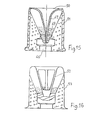
- the basic patent application describes several types of short electrical primers similar to the primer of FIG. 38 in which a charge of live explosive powder 177 such as black powder which acts as an ignition amplifier is used. or "booster".
- This primer comprises a metal body 178 and a central electrode 179 which is several thousand meters higher than the upper plane of the primer.
- This electrode is mechanically held, and is electrically insulated by a tubular mass of plastic material 180.
- The. filament 181 which has the shape of a V, connects in two sections the central trode 179 to the body 178 of the primer. The filament 181 is directly in contact with the powder.
- the "breakdown" of the filament inside the powder charge directly ensures that the combustion of this powder is in progress.
- the choice of the vivacity of the powder will be made according to a pressure / time criterion, as already explained above.
- the wave of propagation of the flame front following this arrangement of the filament is perpendicular to each branch of the filament. This propagation wave will particularly interest the chamber of the barrel.
- the filament 182 is always directly in contact with the powder, but it is placed near the end
Landscapes
- Engineering & Computer Science (AREA)
- General Engineering & Computer Science (AREA)
- Portable Nailing Machines And Staplers (AREA)
- Ignition Installations For Internal Combustion Engines (AREA)
- Automotive Seat Belt Assembly (AREA)
Applications Claiming Priority (4)
| Application Number | Priority Date | Filing Date | Title |
|---|---|---|---|
| FR7824227A FR2433167A1 (fr) | 1978-08-11 | 1978-08-11 | Arme a commande electrique, procede de fonctionnement et munitions utilisees |
| FR7824227 | 1978-08-11 | ||
| FR7917409A FR2460468A2 (fr) | 1978-08-11 | 1979-06-28 | Arme a commande electrique, procede de fonctionnement et munitions utilisees |
| FR7917409 | 1979-06-28 |
Publications (2)
| Publication Number | Publication Date |
|---|---|
| EP0010509A2 true EP0010509A2 (de) | 1980-04-30 |
| EP0010509A3 EP0010509A3 (de) | 1980-12-10 |
Family
ID=26220727
Family Applications (1)
| Application Number | Title | Priority Date | Filing Date |
|---|---|---|---|
| EP79420037A Withdrawn EP0010509A3 (de) | 1978-08-11 | 1979-07-27 | Feuerwaffe mit elektrischer Zündung und deren Wirkungsverfahren; Munition und Zündhütchen dafür |
Country Status (7)
| Country | Link |
|---|---|
| US (1) | US4332098A (de) |
| EP (1) | EP0010509A3 (de) |
| BE (1) | BE92T1 (de) |
| DE (1) | DE2953776A1 (de) |
| FR (1) | FR2460468A2 (de) |
| GB (1) | GB2071826B (de) |
| IT (1) | IT1172213B (de) |
Cited By (5)
| Publication number | Priority date | Publication date | Assignee | Title |
|---|---|---|---|---|
| EP0112526A3 (en) * | 1982-12-21 | 1985-05-29 | Kriegeskorte & Co. Gmbh | Firing device for cartridges, especially for hand fire-arms |
| FR2557689A1 (fr) * | 1983-12-28 | 1985-07-05 | Poudres & Explosifs Ste Nale | Initiateur pyrotechnique utilisant une prise coaxiale |
| GB2172969A (en) * | 1985-03-27 | 1986-10-01 | Scient Cartridge Developments | Shotgun cartridges |
| GB2172967A (en) * | 1985-03-27 | 1986-10-01 | Scient Cartridge Developments | Shotgun cartridge |
| GB2172968A (en) * | 1985-03-27 | 1986-10-01 | Scient Cartridge Developments | Shotgun cartridges |
Families Citing this family (17)
| Publication number | Priority date | Publication date | Assignee | Title |
|---|---|---|---|---|
| EP0587504B1 (de) * | 1992-09-10 | 1997-12-03 | GIAT Industries | Vorrichtung zur Schlussauslösung einer Feuerwaffe mit Hilfe eines Infrarotdetektors |
| US5303495A (en) * | 1992-12-09 | 1994-04-19 | Harthcock Jerry D | Personal weapon system |
| US5503081A (en) * | 1993-11-22 | 1996-04-02 | Fmc Corp | Annular plasma injector |
| US5755056A (en) * | 1996-07-15 | 1998-05-26 | Remington Arms Company, Inc. | Electronic firearm and process for controlling an electronic firearm |
| US6321478B1 (en) * | 1998-12-04 | 2001-11-27 | Smith & Wesson Corp. | Firearm having an intelligent controller |
| US6354033B1 (en) * | 1998-12-17 | 2002-03-12 | Stephan D. Findley | Electric gun |
| IL127932A (en) * | 1999-01-05 | 2004-03-28 | Rafael Armanent Dev Authority | Melting resistors with an electrochemical capacitor as the source of the electric current |
| US6374525B1 (en) * | 1999-04-14 | 2002-04-23 | Nils Thomas | Firearm having an electrically switched ignition system |
| US6668700B1 (en) | 2000-11-13 | 2003-12-30 | Ra Brands, L.L.C. | Actuator assembly |
| US6785996B2 (en) * | 2001-05-24 | 2004-09-07 | R.A. Brands, Llc | Firearm orientation and drop sensor system |
| US6871439B1 (en) | 2003-09-16 | 2005-03-29 | Zyberwear, Inc. | Target-actuated weapon |
| USD587766S1 (en) | 2006-07-20 | 2009-03-03 | Kee Action Sports I Llc | Paintball field marker |
| FI20085179L (fi) * | 2008-02-28 | 2009-08-29 | Patria Weapon Systems Oy | Tukielin ja menetelmä ammuksen laukaisemiseksi |
| US8827706B2 (en) * | 2008-03-25 | 2014-09-09 | Practical Air Rifle Training Systems, LLC | Devices, systems and methods for firearms training, simulation and operations |
| US20160114467A1 (en) | 2014-10-22 | 2016-04-28 | Power Products, Llc | Wrench |
| DE102016109653B4 (de) * | 2016-05-25 | 2020-11-05 | Carl Walther Gmbh | Elektromagnetisch gesteuerte Vorrichtung zur Schussauslösung einer Kurz- oder Langwaffe |
| US10890420B1 (en) * | 2019-07-22 | 2021-01-12 | Murray F Feller | Bullet for an electrically ignited firearm |
Family Cites Families (42)
| Publication number | Priority date | Publication date | Assignee | Title |
|---|---|---|---|---|
| DE251179C (de) * | ||||
| DE206436C (de) * | ||||
| DE25544C (de) * | H. PIEPER in Lüttich, Belgien | Hinterladegewehr mit elektrischer Abfeuerungsvorrichtung | ||
| FR14433E (fr) * | 1911-12-13 | Peuble Et Durif Soc | Dispositif pour la mise en feu des cartouches des fusils électriques | |
| DE47212C (de) * | AMERICAN ELECTRIC ARMS AND AMMUNITION COMPANY in New-York City, 42 Broadway, V. St. A | Neuerung an dem unter Nr. 33599 patentirten elektrischen Zündhütchen | ||
| US3045148A (en) * | 1962-07-17 | Ignition system with transistor control | ||
| FR18307E (fr) * | 1914-03-23 | Jean Gaucher | Nouvelle cartouche pour fusils électriques de tous genres | |
| DE136365C (de) * | ||||
| DE214629C (de) * | 1906-11-13 | |||
| US1084745A (en) * | 1913-09-08 | 1914-01-20 | Union Metallic Cartridge Co | Electric primer. |
| US1362478A (en) * | 1918-05-16 | 1920-12-14 | Homer H Deitrich | Shotgun |
| GB405369A (en) * | 1932-09-03 | 1934-02-08 | Moubray Gore Farquhar | Improvements relating to automatic fire arms |
| FR908038A (fr) * | 1944-11-30 | 1946-03-28 | Dispositif pour tir automatique | |
| FR922904A (fr) * | 1946-02-26 | 1947-06-23 | Fusil de chasse semi-automatique | |
| US2497350A (en) * | 1947-04-30 | 1950-02-14 | Ferda Roman | Pistol shock absorbing device |
| FR1006141A (fr) * | 1947-11-21 | 1952-04-21 | Cartouche à mise de feu électrique | |
| BE540685A (de) * | 1954-08-23 | |||
| LU34265A1 (fr) * | 1955-03-23 | 1956-05-23 | Wasagchemie Ag | Fusée électrique et procédé pour sa fabrication |
| BE548408A (de) * | 1956-04-20 | |||
| US2926566A (en) * | 1956-11-30 | 1960-03-01 | Walter W Atkins | Device for accelerating the ignition of the propellant for a projectile |
| FR1204477A (fr) * | 1957-04-04 | 1960-01-26 | Wasagchemie Ag | Dispositif de mise à feu électrique pour fusée |
| GB1102201A (en) * | 1958-11-18 | 1968-02-07 | Mini Of Technology | Improvements in or relating to initiating systems for propellant charges |
| US3171326A (en) * | 1962-03-29 | 1965-03-02 | Charles H Baker | Recoil friction brake for automatic firearms |
| FR1375369A (fr) * | 1963-11-05 | 1964-10-16 | Dispositif d'alimentation électrique n'utilisant pas de source d'énergie extérieure, pour armes à mise à feu électrique | |
| DE1261022B (de) * | 1965-10-08 | 1968-02-08 | Rheinmetall Gmbh | Stossdaempfer fuer selbsttaetige Feuerwaffen |
| GB1108891A (en) * | 1966-03-05 | 1968-04-03 | Fur Montage Technik Anstalt | Fastener driving tools |
| CH438097A (de) * | 1966-08-18 | 1967-06-15 | Haemmerli Ag | Handfeuerwaffe |
| US3413888A (en) * | 1966-09-14 | 1968-12-03 | Victor B. Kaley | Electrically-actuated cartridge |
| US3690259A (en) * | 1969-04-03 | 1972-09-12 | France Armed Forces | Igniter for electric primer |
| GB1289514A (de) * | 1969-06-18 | 1972-09-20 | ||
| US3613282A (en) * | 1969-09-15 | 1971-10-19 | Olin Corp | Electrical ignition shotgun for firing caseless ammunition |
| US3650174A (en) * | 1970-01-12 | 1972-03-21 | Thomas Sloan Nelsen | Electronic ignition system for firearms |
| DE2053008A1 (de) * | 1970-10-29 | 1972-05-04 | Warninck, Heinz, 2055 Aumuhle | Elektrische Zündung von Treibstoffen |
| US3707797A (en) * | 1970-11-18 | 1973-01-02 | K Ruth | Recoil absorber |
| US3671842A (en) * | 1971-03-22 | 1972-06-20 | Bendix Corp | Battery powered explosive system with relaxation oscillation in charging circuit |
| DE2321708A1 (de) * | 1973-04-28 | 1974-11-07 | Hans Dipl Ing Kuehl | Handfeuerwaffe |
| DE2404053A1 (de) * | 1974-01-29 | 1975-08-28 | Horst Wolff | Ausloese-, insbesondere zuendvorrichtung fuer waffen |
| DE2406933A1 (de) * | 1974-02-14 | 1975-08-28 | Heckler & Koch Gmbh | Abzugseinrichtung fuer elektrisch gezuendete waffen |
| DE2523935A1 (de) * | 1975-05-30 | 1976-12-09 | Diehl Fa | Hochspannungszuendvorrichtung fuer huelsenlose pulverkoerper |
| US4028993A (en) * | 1976-02-23 | 1977-06-14 | The United States Of America As Represented By The Secretary Of The Army | Cycle firing rate reducing assembly for automatic weapons |
| US4019273A (en) * | 1976-06-07 | 1977-04-26 | The United States Of America As Represented By The Secretary Of The Army | Three-barrel pistol, electrode fired |
| US4104970A (en) * | 1977-02-10 | 1978-08-08 | The United States Of America As Represented By The Secretary Of The Navy | Electronic ignition system for liquid explosive |
-
1979
- 1979-06-28 FR FR7917409A patent/FR2460468A2/fr active Granted
- 1979-07-27 EP EP79420037A patent/EP0010509A3/de not_active Withdrawn
- 1979-07-27 GB GB8106688A patent/GB2071826B/en not_active Expired
- 1979-07-27 BE BEBTR92A patent/BE92T1/xx not_active IP Right Cessation
- 1979-07-27 DE DE19792953776 patent/DE2953776A1/de not_active Withdrawn
- 1979-08-13 US US06/066,057 patent/US4332098A/en not_active Expired - Lifetime
-
1981
- 1981-05-21 IT IT86216/81A patent/IT1172213B/it active
Cited By (5)
| Publication number | Priority date | Publication date | Assignee | Title |
|---|---|---|---|---|
| EP0112526A3 (en) * | 1982-12-21 | 1985-05-29 | Kriegeskorte & Co. Gmbh | Firing device for cartridges, especially for hand fire-arms |
| FR2557689A1 (fr) * | 1983-12-28 | 1985-07-05 | Poudres & Explosifs Ste Nale | Initiateur pyrotechnique utilisant une prise coaxiale |
| GB2172969A (en) * | 1985-03-27 | 1986-10-01 | Scient Cartridge Developments | Shotgun cartridges |
| GB2172967A (en) * | 1985-03-27 | 1986-10-01 | Scient Cartridge Developments | Shotgun cartridge |
| GB2172968A (en) * | 1985-03-27 | 1986-10-01 | Scient Cartridge Developments | Shotgun cartridges |
Also Published As
| Publication number | Publication date |
|---|---|
| IT8186216A0 (it) | 1981-05-21 |
| FR2460468A2 (fr) | 1981-01-23 |
| GB2071826B (en) | 1983-04-20 |
| GB2071826A (en) | 1981-09-23 |
| FR2460468B2 (de) | 1983-11-04 |
| EP0010509A3 (de) | 1980-12-10 |
| DE2953776A1 (de) | 1986-04-10 |
| US4332098A (en) | 1982-06-01 |
| IT1172213B (it) | 1987-06-18 |
| BE92T1 (fr) | 1981-04-03 |
Similar Documents
| Publication | Publication Date | Title |
|---|---|---|
| EP0010509A2 (de) | Feuerwaffe mit elektrischer Zündung und deren Wirkungsverfahren; Munition und Zündhütchen dafür | |
| US3854231A (en) | Electrically fired multiple barrel superimposed projectile weapon system | |
| EP0324688B1 (de) | Von der Schulter abzufeuernder Raketenwerfer | |
| FR2538096A1 (fr) | Systeme electromagnetique de lancement de projectiles propulses par poudre | |
| US3427924A (en) | Electrically fired gun and cartridge therefor | |
| EP0766807A1 (de) | Persönliches feuerwaffensystem | |
| US3621781A (en) | Hand weapon and cartridge therefor | |
| FR2781876A1 (fr) | Charge propulsive | |
| EP0362064A1 (de) | Automatische Schnellfeuer-Revolverwaffe | |
| US6374525B1 (en) | Firearm having an electrically switched ignition system | |
| US3495349A (en) | Electrically-fired gun having a vertically movable missile transferring and firing chamber means | |
| FR2509457A1 (fr) | Projectile a trajectoire courte | |
| CA1316422C (fr) | Procede pour lancer des projectiles a des hypervitesses et lanceur mettant en oeuvre ce procede | |
| EP4291850B1 (de) | Lauf mit verriegelbarer munition | |
| FR2687217A1 (fr) | Munition multiple et arme pour la mise en óoeuvre d'une telle munition. | |
| FR2950135A1 (fr) | Allumeur de jet plasma pour un fusil electrique-thermique-chimique (etc), une mitralleuse ou une autre arme a barillet equivalente | |
| FR2609793A1 (fr) | Perfectionnements apportes aux armes a feu destinees a tirer une munition sans etui, et aux munitions de ce type adaptees pour de telles armes | |
| EP0884553B1 (de) | Antriebsgerät für eine die Rückstossenergie begrenzendes Geschoss | |
| FR2788124A1 (fr) | Armes a feu semi-automatiques electriques de petit calibre | |
| FR2649193A1 (fr) | Dispositif pour le lancement d'un projectile | |
| EP2342526A1 (de) | Druckluftmechanismus für eine leichte paintballs oder kunststoffkugeln abfeuernde spielzeugwaffe, die durch pyrotechnische spezialmunition betätigt wird | |
| FR2636131A1 (fr) | Canon electromagnetique a rails pour tir en rafales | |
| FR2581751A1 (fr) | Dispositif pour l'allumage de charges propulsives ou generateurs de gaz | |
| EP0412897A1 (de) | Zweistufengeschütz mit pyrotechnischer Treibladung und elektrischer Zündung | |
| EP0905469B1 (de) | Faustfeuerwaffe für ein Neutralisierungsgeschoss |
Legal Events
| Date | Code | Title | Description |
|---|---|---|---|
| PUAI | Public reference made under article 153(3) epc to a published international application that has entered the european phase |
Free format text: ORIGINAL CODE: 0009012 |
|
| AK | Designated contracting states |
Designated state(s): AT BE CH DE GB IT LU NL SE |
|
| PUAL | Search report despatched |
Free format text: ORIGINAL CODE: 0009013 |
|
| AK | Designated contracting states |
Designated state(s): AT BE CH DE GB IT LU NL SE |
|
| STAA | Information on the status of an ep patent application or granted ep patent |
Free format text: STATUS: THE APPLICATION IS DEEMED TO BE WITHDRAWN |
|
| 110E | Request filed for conversion into a national patent application [according to art. 135 epc] |
Free format text: 8102028 |
|
| 18D | Application deemed to be withdrawn |
Effective date: 19810212 |
|
| REG | Reference to a national code |
Ref country code: DE Ref legal event code: 8580 Free format text: UMWANDLUNG GEM.ART. 135 EPUE. DAS DE-AKZ LAUTET: P 29 53 776.6 |
|
| RIN1 | Information on inventor provided before grant (corrected) |
Inventor name: ESTEVENY, SERGE |