EP0010509A2 - Firearm with electric firing mechanism and process for its operation; ammunition and primers therefor - Google Patents
Firearm with electric firing mechanism and process for its operation; ammunition and primers therefor Download PDFInfo
- Publication number
- EP0010509A2 EP0010509A2 EP79420037A EP79420037A EP0010509A2 EP 0010509 A2 EP0010509 A2 EP 0010509A2 EP 79420037 A EP79420037 A EP 79420037A EP 79420037 A EP79420037 A EP 79420037A EP 0010509 A2 EP0010509 A2 EP 0010509A2
- Authority
- EP
- European Patent Office
- Prior art keywords
- cartridge
- weapon
- circuit
- powder
- une
- Prior art date
- Legal status (The legal status is an assumption and is not a legal conclusion. Google has not performed a legal analysis and makes no representation as to the accuracy of the status listed.)
- Withdrawn
Links
Images


Classifications
-
- F—MECHANICAL ENGINEERING; LIGHTING; HEATING; WEAPONS; BLASTING
- F41—WEAPONS
- F41A—FUNCTIONAL FEATURES OR DETAILS COMMON TO BOTH SMALLARMS AND ORDNANCE, e.g. CANNONS; MOUNTINGS FOR SMALLARMS OR ORDNANCE
- F41A19/00—Firing or trigger mechanisms; Cocking mechanisms
- F41A19/58—Electric firing mechanisms
-
- F—MECHANICAL ENGINEERING; LIGHTING; HEATING; WEAPONS; BLASTING
- F41—WEAPONS
- F41A—FUNCTIONAL FEATURES OR DETAILS COMMON TO BOTH SMALLARMS AND ORDNANCE, e.g. CANNONS; MOUNTINGS FOR SMALLARMS OR ORDNANCE
- F41A25/00—Gun mountings permitting recoil or return to battery, e.g. gun cradles; Barrel buffers or brakes
- F41A25/06—Friction-operated systems
-
- F—MECHANICAL ENGINEERING; LIGHTING; HEATING; WEAPONS; BLASTING
- F41—WEAPONS
- F41A—FUNCTIONAL FEATURES OR DETAILS COMMON TO BOTH SMALLARMS AND ORDNANCE, e.g. CANNONS; MOUNTINGS FOR SMALLARMS OR ORDNANCE
- F41A25/00—Gun mountings permitting recoil or return to battery, e.g. gun cradles; Barrel buffers or brakes
- F41A25/16—Hybrid systems
-
- F—MECHANICAL ENGINEERING; LIGHTING; HEATING; WEAPONS; BLASTING
- F41—WEAPONS
- F41A—FUNCTIONAL FEATURES OR DETAILS COMMON TO BOTH SMALLARMS AND ORDNANCE, e.g. CANNONS; MOUNTINGS FOR SMALLARMS OR ORDNANCE
- F41A3/00—Breech mechanisms, e.g. locks
- F41A3/64—Mounting of breech-blocks; Accessories for breech-blocks or breech-block mountings
- F41A3/78—Bolt buffer or recuperator means
- F41A3/90—Fluid buffers
- F41A3/94—Fluid buffers in combination with spring buffers
-
- F—MECHANICAL ENGINEERING; LIGHTING; HEATING; WEAPONS; BLASTING
- F42—AMMUNITION; BLASTING
- F42C—AMMUNITION FUZES; ARMING OR SAFETY MEANS THEREFOR
- F42C19/00—Details of fuzes
- F42C19/08—Primers; Detonators
- F42C19/12—Primers; Detonators electric
Definitions
- the present invention relates to an electrically operated weapon, its method of operation and the ammunition used.
- the weapon is lighter and cheaper, while retaining traditional ammunition that may have undergone minor changes.
- the time required to recharge the ignition system removed the weapon the ability to shoot two cartridges a few hundredths of a second apart.
- the invention aims to achieve a weapon that does not have all these disadvantages, and which also has a large number of new advantages, allowing to have a weapon effects leading to better use. to better accuracy and better shooting safety.
- Another object of the invention is to provide a power-operated weapon of the above-mentioned type which, in addition, has a very significant decrease in the recoil effect.
- An electrically-controlled weapon is characterized in that it contains at least one DC generator and at least one capacitor charged by said generator, as well as a static switch of the thyristor type which, controlled by means of appropriate control, is likely to cause the discharge of the capacitors by closing the electrical circuit on a resistant element in contact with the powder of the cartridge, so that this element is brought brutally incandescent to put the powder.
- the resistant element is housed in the traditional primer of the cartridge, thus creating the explosion of the primer and the firing of the cartridge.
- the resistant element is directly in contact with the powder charge of the cartridge, which has no primer.
- the rifle inserts through which contact is made with the munition are made of a metal having the best insolubility pattern with the metal of the munitian.
- the weapon comprises at least two accumulation systems, so that at least one is being loaded when the other is operational and keeps the rifle ready to fire.
- a light indicates to the user which circuit is operational.
- the electric circuit comprises, in addition to a firing contactor, two complete circuit disconnectors, namely a first disconnector which remains closed until the weapon is locked, and a second one that remains closed until the hunter, ready to fire, has done the right thing.
- the fingertip button is controlled by other gestures than the conventional finger press on a trigger, it can be controlled either by thumb pressure on the upper part of the butt or on the pressure of the thumb. on the support plate of the butt, or by an action of the teeth or the eyelid.
- the firing key is controlled off the rifle, either by a wire or by radio.
- the weapon comprises an infra-red viewfinder sensitive to the heat of the game, or a sound-sensitive sound receiver triggering the firing button when the aiming is perfect.
- a digital display indicator is embedded in the butt or elsewhere to indicate the number of cartridges fired.
- a method for the operation of the electrically operated weapon according to the invention is characterized in that the brutal discharge of the capacitor is transmitted to a metal key housed where the firing pin of the rifle is usually located, the circuit being closed by the ramp. barrel mass intimately connected to the sleeve of the cartridge
- the metal key that replaces the conventional beader firmly presses on the bottom of the primer at the time of the shot, without crossing the bottom.
- a cartridge leader usable with the weapon according to the invention is characterized in that it comprises spun directly into contact with the powder, and connected between a cylindrical metal body and an axial electrode extending to the rear end of the base.
- the filament is constituted by a metal wire.
- the filament is constituted by a layer of metal deposited on an insulating body.
- the filament is constituted by a metal fuse foam.
- the weapon comprises on the one hand a movable assembly comprising at least one yoke, guiding means being provided to allow the relative sliding of the two assemblies, in the longitudinal direction,
- the first assembly which comprises the barrel and the cylinder head, is mounted to slide on a slideway secured to the second assembly, the second assembly comprising the butt.
- the damping means comprise on the one hand a helical spring compressed between the two sets, and on the other hand at least one pneumatic chamber delimited between a cylinder and a piston secured respectively soft sets, and connected to the atmosphere through a calibrated orifice to fill when the two sets are close to each other.
- the damping means comprise on the one hand at least one helical spring compressed between the two sets, and on the other hand a friction system mounted to brake the relative sliding of the two sets.
- the friction system comprises on the one hand a plate integral with one of the two assemblies, and on the other hand two transverse pads mounted to slide on the other assembly, each pad carrying a friction lining on his face in. contact with the plate, while springs permanently apply the pads on both sides of the plate.
- each pad is constituted by a piston which delimits a chamber communicating with the chamber receiving a cartridge, so that the rise in pressure due to the firing a cartridge increases the clamping force of the um of pstins on the plate.
- the first set is constituted by a breech
- the second set comprises the barrel and the stock of the spade the breech being mounted to slide in the barrel and being biased forwards.
- the joint plane separating the barrel from the bolt box being located at the front of the chamber which receives the cartridge.
- two rotors are mounted to rotate on a small carriage freely sliding along the barrel, each rotor being also secured to a toothed pinion meshing with a longitudinal rack integral with the barrel.
- the cylinder head is secured to a small piston which is engaged in a chamber full of an incompressible fluid, the free end of the small piston being located at the rear of a large piston that the small piston passes through, the large piston delimiting the said chamber from the front and being constantly subjected to the action of springs which recall it towards the rear.
- the moving parts of the anti-recoil mechanism comprise magnetic masses that move in a splenoid winding by generating an electric current that can be recovered to recharge the supply batteries of the electronic device. ignition.
- a cartridge leader usable with the weapon according to the invention comprises a filament directly in contact with the powder, and connected between a cylindrical metal body and an electrode, and is characterized in that the filament is y-shaped to connect in two sections the central electrode to the body of the primer.
- the filament is disposed near the front end of the load p Udre of the cartridge, the flame front then propagating back and forth in the cartridge, which allows to obtain complete combustion of the powder.
- the cartridge carries no socket, a filament located directly in contact with the powder charge, at the front end of this powder charge, being connected via electrodes to rings. collectors flush with the outer cylindrical surface of the plastic body of the cartridge.
- FIG. 1 shows the schematic diagram of the electronic box for firing a weapon according to the invention.
- This box contains: a battery of cells or accumulators 1, an integrated circuit 2, a transistor 3, a transformer 4, and a diode 5 in its “converter” section, as well as a thyristor 6, a diode 7, capacitors 8 and 9, an expansion switch 10 and a safety switch 11 in its section "control circuit”.
- the cartridge 12 provided with an electric primer 13 is shown very schematically: it will be described later in detail.
- Transistor 3 is used as a switch. When closed, the battery 1 is directly connected to the primary transformer winding 4. Any variation in voltage in the primary winding causes a variation in intensity, and therefore a variation in flux in the transformer. the core of the transformer 4. The establishment of a collector current 14 of the transistor 3 is equivalent to an alternating opening and closing of the supply circuit of the primary winding of the transformer 4. The frequency of this phenomenon is set by the integrated circuit 2 which takes into account the optimum efficiency of the transformer 4.
- FIG. 2 shows the stacks 1 and the casing 17 shown diagrammatically in FIG. 1. The latter organs are housed and targeted in the stock.
- the contacting members are shown in FIG. 4. It can be seen that the conventional striker is replaced by an elongated metal key 18 which is guided in guides 19 and 20 of insulating material, and which is constantly pushed towards the cartridge. by a spring 21 0
- This spring is made of a material having a high stiffness, a very good electrical conductivity, and excellent resistance to corrosion of the contact.
- the spring is connected to one of the terminals of the power circuit, the other terminal being connected to the mass of the rifle, by means of a screw 22.
- the switch 10 is constituted here by a microswitch which is controlled directly by the trigger 23.
- the free rear end of this trigger constantly tends to be pushed in abutment against a fixed pin 24 by a helical spring 25 whose voltage is adjusted by a screw 26.
- the parts of the rifle charged with making contact with the munition are made of a metal having, with the metal of the munition, the best insolubility diagram.
- the base of the ammunition is brass, that is to say an alloy where copper dominates
- the parts of the rifle in contact with the munition will be advantageously made of tungsten or molybdenum.
- the same contacting members may be retained, but by adding a metal insert 27 in the bottom of the socket to make an electrical contact. enter one end of the filament 28 and the ejector 29 of the rifle, the other end of the filament being in contact with the key.
- FIGs 8 and 9 show, on an enlarged scale, the constitution of the electric primer 13 of Figure 4.
- This primer comprises a tubular metal body 35 which encloses an insulator 36.
- An electrode 37 disposed axially in the primer, is embedded in the insulator 36, and is electrically connected to the body 35 by a filament 38.
- the filament may consist of a straight wire disposed diametrically at the front end of the tubular body 35 and crimped on the one hand on the body 35 and secondly on the electrode 37.
- the filament 38 may also take the form of a spirally wound wire.
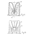
- Figures 11 to 18 show various examples of electrical primers, according to variants.
- the filament is constituted by a very thin steel strip 39 also acting as a primer body.
- the part of the strip which is not in contact with the base of the cartridge volatilises and ignites the powder.
- the filament is constituted by a thin layer of metal 40 deposited on an insulating body 41.
- the metal layer whose thickness is for example of the order of 2 microns, can be deposited either electrolytically, or by evaporation under vacuum. These manufacturing processes are easily industrialized and rigorously reproducible from one primer to another.
- the filament is constituted by a very thin metal cup 42 whose upper part, or before, comprises cells 43 between which are defined four fuse branches 44 (visible on the folded section shown in fine lines) .
- the cells make it possible to reduce as much as possible the metal section to be volatilized under the effect of the electric discharge.
- the center of the front portion of the cup 42 is resistance welded on the front end of the electrode 37.
- the filament is constituted by a magnesium fuse foam or tungsten-rhenium 4 5 of the type used in photographic flash bulbs.
- this detonating powder increasing the effectiveness of the primer.
- This powder may for example be housed under the strip 39 of FIG. 11, and under the front part of the metal cup 42 of FIG. 13.
- the powder may also be contained inside the primer by a film of sealing located at the top of the primer provision that is adopted for the following two cases
- the electrode 46 is shortened, and the filament 47 extends inside a crater provided at the front of the insulator 48.
- the detonating powder 49 is trapped in this crater thanks to the sealing film 50 disposed against the forward end of the tubular metal body 51.
- the filament 52 is constituted by a folded rearward extension of the front end of the tubular metal body 53.
- FIG. 19 shows a weapon according to another variant of the invention.
- This weapon conforms to the general dispositions already described, but it comprises on the one hand a fixed subassembly comprising the butt 101 and the front wood 102. (Fig 21) and secondly a movable subassembly comprising the barrel 103 and the cylinder head 104 (Fig 20). Slides 105 are provided to allow the relative longitudinal sliding of the two subsets.
- This damping device can be of any type and known, such as the type of pneumatic hydraulic dampers, electromagnetic mechanics, and others.
- a damping of the recoil is obtained by the depression of air chambers, the weapon comprising two subassemblies which can slide relative to one another, while the link that unites the two subsets to each other is reduced to an electrical conductor.
- This rifle comprises, on the one hand, a mobile subassembly consisting of two superimposed guns 110 and a cylinder head 111, and on the other hand a fixed subassembly which bears on the shoulder of the user and which is composed of the butt 11 2 and the front wood 113.
- the butt 112 is secured to a support 114 in which slides a piston 115 that a rod 1 16 connects to the bottom of the cylinder head 111.
- the piston 115 which is provided of a lip seal 117, defining in a bore of the support 114 a front chamber 118 which is only connected to the atmosphere via a calibrated channel 119 formed in the rod 116.
- a rear chamber 120 which is delimited against the rear wall of the support 114 inside a bell-shaped piston 121 capping the rear of the support 114, is only connected to the atmosphere via the clearance provided between the adjacent cylindrical walls said piston 121 and the support 114.
- the piston 121 is connected to the piston 115 by the intermediate rod 122 coaxial with the rod 116, and located at the rear of the latter.
- helical spring 123 is compressed between the support 114 and the bottom of the cylinder head 111.
- the cylinder head 111 also contains the electric firing device which remains the same as before.
- This positive device mainly comprises a switch 124 and an electrode holder 125.
- the two electrodes 126 are mounted on this electrode holder, and are subjected to a force via a helical spring 127, so that when the guns are locked, these electrodes ensure contact with the respective electrical primers of the cartridges.
- Sleeves 128 and 129 are arranged around each electrode to electrically isolate it from the bottom of the corresponding barrel, and secondly of the electrode holder The arrival of the electric current in the electrodes is provided by means of a very-flexible wire 180, with a cross section of 1 to 2 mm 2.
- reaction force - characteristic of the retum - is supported on the bottom of the breech and propels the barrel / bolt assembly backwards.
- the spring 123 limits this displacement.
- the pistons 115 and 121 undergo the same law of movement to the rear dead point: a certain amount of air is introduced into the chambers 118 and 120.
- the chambers 118 and 120 rise in pressure to slow and dampen this movement until the chambers 118 and 120 are at atmospheric pressure.
- the damping of the recoil is due to the friction of two parts one on the other.
- the movable subassembly which comprises the guns 110 and the cylinder head 111 is braked during its rearward movements by the friction of gaskets 132 on a part 133 of the fixed subassembly.
- the movable subassembly arrives at the rear dead center, its return forward is ensured by the expansion of the springs 134 resting on the cylinder head 111.
- the clamping force of the packings 132 on the piece 133 is ensured by the washer compression 135 elastics called "BELLEVILLE washers".
- the clamping force is slaved to the pressure in the combustion chamber at the time of ignition of the cartridge through communication channels 36 provided between the chamber containing the cartridge and the enclosure containing the brakes
- This particular arrangement of the linings makes it possible to better balance the friction forces between the movable linings and the fixed surfaces associated with the stock.
- the damping of the recoil force is obtained by action of a magnetic field on a polar mass.
- the movable subassembly is constituted by the two cu-lasses 144 while the fixed subassembly comprises the superposed rods 145, the butt 146, the front wood and the boot with fixed breeches 148.
- Each breech is mounted for sliding in the cylinder head box 148, which constitutes the rear of the guns, and is permanently urged forward by a helical spring 149.
- the joint plane 150 separating the guns from the headbox is located the front of the rooms 151 receiving the cartridges.
- the damping of the recoil is obtained by setting rearward movement of the bolt relative to the rest of the rifle, thanks to the inertia of the bolt.
- the springs 149 exert, via the yokes 144, a pre-load on the sockets.
- the keys 153 which are electrically isolated, are in contact with the respective central electrodes of the electric primers.
- a spring 154 maintains this contact regardless of the dimensional variations of the plane of the socket relative to the plane of the primer.
- the electrical energy required for firing is conveyed to a distribution ring 155 by a conductor 156, while a device 157 comprising two brushes and a spring conveys the energy required to the central electrode to the central electrode. departure.
- the isolation of all this electrical circuit is provided by a plastic such as, for example, Bakelite or others.
- the shooter presses on the trigger 158, it closes the switch 159, which has the effect of controlling the trigger of the thyristor of the electronic circuit corresponding to the barrel, and thus causes the volatilization of the fuse wire of the primer which fires with powders.
- two triggers are provided 160.
- the sleeve limits the soft tively forward the socket, to imprison it so in the breech.
- the finger 61 will move back under the action of the stop 162, and transmit this movement at right angle to a rod 16 which will lift the trigger 160.
- the released sleeve will then be ejected to the before the shooter, which ensures better security.
- the rifle may be made with a traditional, revolving stick, according to FIG. 24.
- the rifle may also advantageously be made in accordance with the provisions of FIG. 25, that is to say with two keys of control 164 located on the left and right of the handle according to whether the shooter is right-handed or left-handed.
- detents can be made more or less soft to use thanks to adjustable stops.
- Figures 35 to 37 show two examples of weapons made according to this principle, and provided with simple and original kinematics such that these weapons are physiologically the effect of recoilless weapons.
- two rotors 165 are mounted on a small carriage 166 which slides freely along the barrels 167. Each rotor is also secured to a toothed pinion 168 or 169 meshing with a longitudinal rack 170 or 171 solidarity with the canons.
- the yoke 172 is secured to a small piston 173 which is engaged in a chamber 174 full of an incompressible fluid.
- the small piston passes through a large piston 175, its free end being located at the rear of the large piston which delimits the front of the chamber 174.
- the large piston is subjected in! permanence to the action of return springs 176 which recall it to the rear.
- the end of the recessed assembly tends to reduce the volume available in the chamber 174, the com pressing this chamber by throwing the large piston 175 forward.
- the springs 176 which connect the two end walls of the chamber 174 absorb the desired portion of the kinetic energy.
- the moving parts of the anti-kickback mechanism comprises magnetic masses which, by moving in a solenoid winding, generate an electric current being receivable - father to recharge the battery packs of the electronic device Firing.
- the basic patent application describes several types of short electrical primers similar to the primer of FIG. 38 in which a charge of live explosive powder 177 such as black powder which acts as an ignition amplifier is used. or "booster".
- This primer comprises a metal body 178 and a central electrode 179 which is several thousand meters higher than the upper plane of the primer.
- This electrode is mechanically held, and is electrically insulated by a tubular mass of plastic material 180.
- The. filament 181 which has the shape of a V, connects in two sections the central trode 179 to the body 178 of the primer. The filament 181 is directly in contact with the powder.
- the "breakdown" of the filament inside the powder charge directly ensures that the combustion of this powder is in progress.
- the choice of the vivacity of the powder will be made according to a pressure / time criterion, as already explained above.
- the wave of propagation of the flame front following this arrangement of the filament is perpendicular to each branch of the filament. This propagation wave will particularly interest the chamber of the barrel.
- the filament 182 is always directly in contact with the powder, but it is placed near the end
Landscapes
- Engineering & Computer Science (AREA)
- General Engineering & Computer Science (AREA)
- Portable Nailing Machines And Staplers (AREA)
- Automotive Seat Belt Assembly (AREA)
- Ignition Installations For Internal Combustion Engines (AREA)
Abstract
Le dispositif de mise à feu comprend un condensateur (8) chargé à l'aide d'une batterie (1) par l'intermédiaire d'un circuit comprenant un circuit intégré (2), un transistor (3), un transformateur (4) et une diode (5). En appliquant une impulsion sur la gachette (15) d'un thyristor (6), on décharge brutalement le condensateur (8) dans une amorce électrique (13) de la cartouche, pour provoquer la mise à feu.The firing device comprises a capacitor (8) charged with a battery (1) via a circuit comprising an integrated circuit (2), a transistor (3), a transformer (4) ) and a diode (5). By applying a pulse on the trigger (15) of a thyristor (6), the capacitor (8) is suddenly discharged into an electrical primer (13) of the cartridge to cause firing.
L'arme à feu est également équipée d'un dispositif amortisseur qui permet d'amortir le déplacement relatif de l'ensemble culassecannon par rapport à la crosse.The firearm is also equipped with a damping device that damps the relative movement of the assembly culassecannon relative to the butt.
L'amorce électrique (13) de la cartouche est composée d'un corps métallique cylindrique, d'un isolant interne et d'une électrode axiale noyée dans l'isolant, un filament situé à proximité de la poudre étant branché entre le corps métallique et l'extrémité avant de l'électrode axiale qui s'étend jusqu'à l'extrémité arrière de la douille.
Description
La présente invention concerne une arme à commande électrique, son procédé de fonctionnement et les munitions utilisées.The present invention relates to an electrically operated weapon, its method of operation and the ammunition used.
On a déjà préconisé et essayé avec succès des systèmes électriques ou électroniques pour la mise à feu d'une arme de tir.We have already advocated and successfully tried electrical or electronic systems for firing a shooting weapon.
Ces systèmes sont séduisants, car ils suppriment une grande partie de la mécanique des fusils traditionnels, seuls étant conservés les mécanismes de verrouillage et d'extraction.These systems are attractive because they remove much of the mechanics of traditional rifles, only the locking mechanisms and extraction.
De ce fait, l'arme est plus légère et de meilleur prix, tout en conservant des munitions traditionnelles ayant subi éventuellement des transformations mineures.As a result, the weapon is lighter and cheaper, while retaining traditional ammunition that may have undergone minor changes.
Malgré tous ces atouts, la mise à feu électrique ou électronique n'a pas eu le succès attendu sur le marché de l'arme, et ce à cause d'un grand nombre d'inconvénients concernant, en particulier, le manque de fiabilité, ainsi qu'une sécurité et une sûreté douteuses. Ce manque de fiabilité découlait d'un nombre élevé de longs feux dûs, dans la majorité des cas, à des défauts de contact, par corrosion des contacts, présence d'humidité et autres.Despite all these advantages, the electric or electronic firing has not had the expected success in the weapon market, and this because of a large number of disadvantages concerning, in particular, the unreliability, as well as questionable security and safety. This unreliability resulted from a high number of long burns due, in most cases, to contact, contact corrosion, moisture and other defects.
D'autre part, le temps nécessaire à la recharge du système d'allumage enlevait à l'arme la possibilité de tirer deux cartouches à quelques centièmes de seconde d'intervalle.On the other hand, the time required to recharge the ignition system removed the weapon the ability to shoot two cartridges a few hundredths of a second apart.
Le manque de sécurité et de sûreté provenait de la faiblesse de l'effort requis pour actionner la touche électrique du type mécanique en comparaison avec la gachette à gachette ordinaire. Cette touche électrique comportait un ensemble de pièces mécaniques à la Manière d'un interrup- teur et, sous l'effet de chocs et d'accélérations brutales, pouvait fermer le circuit d'une façon intempestive et mettre ainsi l'arme à feu.The lack of safety and security came from the weakness of the effort required to actuate the mechanical-type electrical key in comparison with the standard trigger trigger. This electric key included a set of mechanical parts to the Way of a tor interruption and under the effect of impacts and sudden acceleration, could close the circuit of an untimely manner and thus put the firearm.
L'invention a pour but de réaliser une arme qui ne présente pas tous ces invonvénients, et qui présente par ailleurs un grand nombre d'avantages nouveaux, en permettant de disposer sur une arme d'effets conduisant à une meilleure utilisation,. à une meilleure précision et à une meilleure sécurité de tir.The invention aims to achieve a weapon that does not have all these disadvantages, and which also has a large number of new advantages, allowing to have a weapon effects leading to better use. to better accuracy and better shooting safety.
Par ailleurs, dans l'industrie de l'arme, on se pré occupe de plus en plus du problème de recul, Naguère, l'arme de chasse représentait la fabrication principale de la profession, et la cadence de tir très faible du tir sur gibier rendait acceptable le recul des armes usuelles, quitte à utiliser une plaque d'élastomère assurant un amortissement très partiel. A présent, l'apparition de l'arme de tir sportif, dit : tir au pigeon ou ball-trap, ou toute autre forme que peut revêtir ce sport d'adresse, rend absolument nécessaire l'adoption d'une solution. Il n'est pas rare, en effet, qu'un tireur ait plus de 100 cartouches à tirer dans un après-midi de concours, et il en résulte au fur et à mesure une meurtrissure croissante de l'épaule qui, en place nuit à la précision du tir.On the other hand, in the weapon industry, we are more and more concerned about the problem of hindsight. In the past, the hunting weapon was the main manufacture of the profession, and the very low rate of fire fired from game made acceptable the retreat of the usual weapons, even if to use a plate of elastomer ensuring a very partial damping. Now, the appearance of the sports shooting weapon, called pigeon shooting or pigeon shooting, or any other form that can take this sport of skill, makes absolutely necessary the adoption of a solution. It is not uncommon, in fact, that a shooter has more than 100 cartridges to shoot in an afternoon of competition, and it results as and when a growing bruise of the shoulder which, in place night to the accuracy of the shot.
A l'heure actuelle, aucune solution commode et satisfaisante n'a pu être trouvée. En effet, un frein de se- cul ne peut être efficace que s'il existe un degré de liberté entre une partie mobile et une partie fixe. Or, dans les armes actuelles à percussion, il existe toute une chai- ne cinématique continue qui relie le sous-ensemble crosse mécanisme-percussion au sous-ensemble canon-culasse-extran- tion. Cette chaîne cinématique empêche d'introduire le mou- vement relatif nécessaire à l'absorption progressive de l'énergie du recul.At present, no convenient and satisfactory solution has been found. In fact, a seismic brake can only be effective if there is a degree of freedom between a moving part and a fixed part. Now, in the current percussive weapons, there is a whole continuous kinematic chain linking the mechanism-percussion sub-assembly to the barrel-breech-extrusion subassembly. This kinematic chain prevents the introduction of the relative movement necessary for the gradual absorption of the recoil energy.
L'invention a également pour but de réaliser une arme à commande électrique du type sus-mentionné qui, en plus, présente une diminution très sensible de l'effet de recul.Another object of the invention is to provide a power-operated weapon of the above-mentioned type which, in addition, has a very significant decrease in the recoil effect.
Une arme à commande électrique suivant l'invention est caractérisée en ce qu'elle renferme au moins un générateur de courant continu et au moins un condensateur chargé par ledit générateur, ainsi qu'un interrupteur statique du type thyristor qui, commandé par un moyen de commande approprié, est susceptible de provoquer la décharge des condensateurs par fermeture du circuit électrique sur un élément résistant en contact avec la poudre de la cartouche, de façon que cet élément soit porté brutalement à incandescence pour mettre la poudre à feu.An electrically-controlled weapon according to the invention is characterized in that it contains at least one DC generator and at least one capacitor charged by said generator, as well as a static switch of the thyristor type which, controlled by means of appropriate control, is likely to cause the discharge of the capacitors by closing the electrical circuit on a resistant element in contact with the powder of the cartridge, so that this element is brought brutally incandescent to put the powder.
Suivant une caractéristique supplémentaire de l'invention, l'élément résistant est logé dans l'amorce traditionnelle de la cartouche, créant ainsi l'explosion de l'amorce et la mise à feu de la cartouche.According to a further characteristic of the invention, the resistant element is housed in the traditional primer of the cartridge, thus creating the explosion of the primer and the firing of the cartridge.
Suivant une variante de l'invention, l'élément résistant est directement en contact avec la charge de poudre de la cartouche, qui ne comporte pas d'amorce.According to a variant of the invention, the resistant element is directly in contact with the powder charge of the cartridge, which has no primer.
Suivant une caractéristique supplémentaire de l'in- parties du fusil par l'intermédiaire desquelles le contact est établi avec la munition sont faites en un métal présentant, avec le métal de la munitien, le meilleur diagramme d'insolubilité.According to an additional feature of the rifle inserts through which contact is made with the munition are made of a metal having the best insolubility pattern with the metal of the munitian.
Suivant une caractéristique supplémentaire de l'invention, l'arme comporte au moins deux systèmes d'accumulation, de sorte qu'un au moins est en cours de chargement quand l'autre est opérationnel et maintient le fusil prêt à tirer.According to a further feature of the invention, the weapon comprises at least two accumulation systems, so that at least one is being loaded when the other is operational and keeps the rifle ready to fire.
Suivant une caractéristique supplémentaire de l'invention, un voyant lumineux indique à l'utilisateur quel est le circuit qui est opérationnel.According to a further feature of the invention, a light indicates to the user which circuit is operational.
Suivant une caractéristique supplémentaire de l'invention, le circuit électrique comporte, en plus d'un contacteur de mise à feu, deux sectionneurs complets de circuit, a savoir un premier sectionneur qui reste fermé tant que l'arme n'est pas verrouillée, et un second qui reste fermé tant que le chasseur, prêt à tirer, n'a pas accompli le geste adéquat.According to a further feature of the invention, the electric circuit comprises, in addition to a firing contactor, two complete circuit disconnectors, namely a first disconnector which remains closed until the weapon is locked, and a second one that remains closed until the hunter, ready to fire, has done the right thing.
Suivant une caractéristique supplémentaire de l'invention, la touche de mise a fau est commandés par d'autre gestes que l'appui classique du doigt sur une gachette,, elle peut être commandée soit par pression du pouce à la partie supérieure de la crosse, soit pnr pression de l'péa le sur la plaque d'appui de la crosse, soit encore par une action des dents ou de la paupière.Next to an additional feature of the in In other words, the fingertip button is controlled by other gestures than the conventional finger press on a trigger, it can be controlled either by thumb pressure on the upper part of the butt or on the pressure of the thumb. on the support plate of the butt, or by an action of the teeth or the eyelid.
Suivant une variante de l'investion, la touche de mise à feu est commandée hors du fusil, soit pat un fil, soit par radio.According to a variant of the investion, the firing key is controlled off the rifle, either by a wire or by radio.
Suivant une autre variante de l'invention l'arme comporte un viseur à infra-rouges sensible à la chaleur du gibier, ou un récepteur sonore sensible à son bruit déclen chant la touche de mise à feu quand la visée est parfaite.According to another variant of the invention, the weapon comprises an infra-red viewfinder sensitive to the heat of the game, or a sound-sensitive sound receiver triggering the firing button when the aiming is perfect.
Suivant une caractéristique supplémentaire de l'in vention, un indicateur à affichage numérique est encastré dans la crosse ou ailleurs pour indiquer le nombre de cartouches tirées.According to an additional feature of the invention, a digital display indicator is embedded in the butt or elsewhere to indicate the number of cartridges fired.
Un procédé pour le fonctionnement de l'arme à commande électrique suivant l'invention est caractérisé en ce que la décharge brutale du condensateur est transmise à un touche métallique logée là où est situé habituellement le percuteur du fusil, le circuit se fermant par le rampur de masse du canon lié intimement à la douille de la cartoucheA method for the operation of the electrically operated weapon according to the invention is characterized in that the brutal discharge of the capacitor is transmitted to a metal key housed where the firing pin of the rifle is usually located, the circuit being closed by the ramp. barrel mass intimately connected to the sleeve of the cartridge
Suivant une caractéristique supplémentaire de vention, la touche métallique qui remplace le perouteur classique appuie fermement sur le fond de l'amorce au ma- ment du tir, sans traverser ce fond.According to an additional feature of vention, the metal key that replaces the conventional beader firmly presses on the bottom of the primer at the time of the shot, without crossing the bottom.
Suivant une variante de l'invention, la touche metallique qui remplace le percuteur classique perfora le fond de l'amorce au moment du tir pour venir en contact avec une borne d'un filament, l'autre borne de ce filament étant à la masse par l'intermédiaire du culot de la ear- touche.According to a variant of the invention, the metal key that replaces the conventional striker perforated the bottom of the primer at the time of firing to come into contact with a terminal of a filament, the other terminal of this filament being grounded. through the base of the ear.
Suivant une variante de l'invention, la décharge brutale du condensateur porte à incandescence le fond du culot de la cartouche,According to a variant of the invention, the brutal discharge of the capacitor incandescent the bottom of the base of the cartridge,
Une amorce de cartouche utilisable avec l'arme sui vant l'invention est caractérisée en ce qu'elle comporte filaient directement en contact avec la poudre, et branché entre un corps métallique cylindrique et une électrode axiale s'étendant jusqu'à l'extrémité arrière du culot.A cartridge leader usable with the weapon according to the invention is characterized in that it comprises spun directly into contact with the powder, and connected between a cylindrical metal body and an axial electrode extending to the rear end of the base.
Suivant une caractéristique supplémentaire de l'invention, le filament est constitué par un fil métallique.According to a further characteristic of the invention, the filament is constituted by a metal wire.
Suivant une variante de l'invention, le filament est constitue par une couche de métal déposée sur un corps isolant.According to a variant of the invention, the filament is constituted by a layer of metal deposited on an insulating body.
Suivant une autre variante de l'invention; le filament est constitué par une mousse fusible métallique.According to another variant of the invention; the filament is constituted by a metal fuse foam.
Suivant une caractéristique supplémentaire de l'invention, l'arme comporte d'une part un ensemble mobile comprenant au moins une culasse, des moyens de guidage étant prévus pour permettre le coulissement relatif des deux ensembles, dans le sens longitudinal,According to a further feature of the invention, the weapon comprises on the one hand a movable assembly comprising at least one yoke, guiding means being provided to allow the relative sliding of the two assemblies, in the longitudinal direction,
Suivant une caractéristique supplémentaire de l'invention, le premier ensemble, qui comprend le canon et la culasse, est monté pour coulisser sur une glissière solidaire du deuxième ensemble, ce deuxième ensemble comprenant la crosse.According to a further feature of the invention, the first assembly, which comprises the barrel and the cylinder head, is mounted to slide on a slideway secured to the second assembly, the second assembly comprising the butt.
Solvant une caractéristique supplémentaire de l'invention, les moyens amortisseurs comprennent d'une part un ressort hélicoïdal comprimé entre les deux ensembles, et d'autre part au moins une chambre pneumatique délimitée entre un cylindre et un piston solidaires respectivement des doux ensembles, et reliée à l'atmosphère par l'intermédiaire d'un orifice calibré pour se remplir lorsque les deux ensembles se rapprochent l'un de l'autre.Solvent a further feature of the invention, the damping means comprise on the one hand a helical spring compressed between the two sets, and on the other hand at least one pneumatic chamber delimited between a cylinder and a piston secured respectively soft sets, and connected to the atmosphere through a calibrated orifice to fill when the two sets are close to each other.
Suivant une variante de l'invention, les moyens amortisseurs comprennent d'une part au moins un ressort hélicoïdal comprimé entre les deux ensembles, et d'autre part un système à friction monté pour freiner le coulissement relatif des deus ensembles.According to a variant of the invention, the damping means comprise on the one hand at least one helical spring compressed between the two sets, and on the other hand a friction system mounted to brake the relative sliding of the two sets.
Suivant une caractéristique supplémentaire de l'invention, le système à friction comprend d'une part une plaque solidaire de l'un des deux ensembles, et d'autre part deux patins transversaux montés pour coulisser sur l'autre ensemble, chaque patin portant une garniture de friction sur sa face en. contact avec la plaque, tandis que des ressorts appliquent en permanence les patins de part et d'autre de la plaque.According to a further feature of the invention, the friction system comprises on the one hand a plate integral with one of the two assemblies, and on the other hand two transverse pads mounted to slide on the other assembly, each pad carrying a friction lining on his face in. contact with the plate, while springs permanently apply the pads on both sides of the plate.
Suivant une caractéristique supplémentaire de l'invention, dans le cas d'une arme à canon doubles chaque patin est constitué par un piston qui délimita une chambre communiquant avec la chambre recevant une cartouche, si bien que l'élévation de la pression due à la mise à feu d'une cartouche augmente la force de serrage de l'um des pstins sur la plaque.According to a further feature of the invention, in the case of a double-barreled weapon each pad is constituted by a piston which delimits a chamber communicating with the chamber receiving a cartridge, so that the rise in pressure due to the firing a cartridge increases the clamping force of the um of pstins on the plate.
Suivant une variante de l'invention, dans le cas d'une arme à canon double, le système à friction comprend :
- - deux surfaces de frottement planes solidaires de l'un des deux ensembles, et situées en vis-à-vis ;
- - un alésage transversal aménagé dans l'autre ensemble, et s'étendant entre les deux surfaces de frottement ;
- - deux patins engagés pour coulisser dans l'alésage transversal, chacun à une extrémité de cet alésage chaque patin portant une garniture de friction sur sa faca on contact avec la surface de frottement correspondante
- - un piston central monté pour coulisser dans l'alésage transversal ;
- - sur chaque face du piston central, un téton axial susceptible de buter contre l'un des patins ;
- - autour de chaque téton axial, au moins uns xen delle élastique comprimée entre le piston central et l'un des patins ;
- - deux conduits établissant chacun un passage en- tre une chambre recevant une cartouche et une chambre del mitée entre l'un des patins et le piston central.
- two flat friction surfaces integral with one of the two assemblies, and located opposite each other;
- - A transverse bore formed in the other set, and extending between the two friction surfaces;
- two sliders engaged to slide in the transverse bore, each at one end of this bore each pad carrying a friction lining on its faca in contact with the corresponding friction surface
- a central piston mounted to slide in the transverse bore;
- - On each face of the central piston, an axial stud may abut against one of the pads;
- - around each axial stud, at least one xen elastic delle compressed between the central piston and one of the pads;
- - establishing two ducts each one passageway in- t re a chamber receiving a cartridge and a del mitée chamber between one of the pads and the central piston.
Suivant une variante de l'invention, le premiser ensemble est constitué par une culasse, tandis que le drur- ième ensemble comprend le canon et la crosse de l'arae le culasse étant montée pour coulisser dans le canon et étant rappelée vers l'avant en permanence par un ressort hélicol- dal, le plan de joint séparant le canon de la boite à culasse étant situé à l'avant de la chambre qui reçoit la cartouche.According to a variant of the invention, the first set is constituted by a breech, while the second set comprises the barrel and the stock of the spade the breech being mounted to slide in the barrel and being biased forwards. permanently by a helical spring, the joint plane separating the barrel from the bolt box being located at the front of the chamber which receives the cartridge.
Suivant une autre variante de l'invention, deux toupies sont montées pour tourner sur un petit chariot coulissant librement le long du canon, chaque toupie étant par ailleurs solidaire d'un pignon denté engrenant avec une crémaillère longitudinale solidaire du canon.According to another variant of the invention, two rotors are mounted to rotate on a small carriage freely sliding along the barrel, each rotor being also secured to a toothed pinion meshing with a longitudinal rack integral with the barrel.
Suivant une autre variante de l'invention, la culasse est solidaire d'un petit piston qui est engagé dans une chambra pleine d'un fluide incompressible, l'extrémité libre du petit piston étant située à l'arrière d'un gros piston que le petit piston traverse, le gros piston délimitant par l'avant ladite chambre et étant soumis en permanence à l'action de ressorts qui le rappellent vers l'arrière.According to another variant of the invention, the cylinder head is secured to a small piston which is engaged in a chamber full of an incompressible fluid, the free end of the small piston being located at the rear of a large piston that the small piston passes through, the large piston delimiting the said chamber from the front and being constantly subjected to the action of springs which recall it towards the rear.
Suivant une autre variante de l'invention, les pièces en mouvement du mécanisme anti-recul comportent des masses magnétiques qui se déplacent dans un enroulement splénoïde en engendrant un courant électrique que l'on peut récupérer pour recharger les batteries d'alimentation du dispositif électronique d'allumage.According to another variant of the invention, the moving parts of the anti-recoil mechanism comprise magnetic masses that move in a splenoid winding by generating an electric current that can be recovered to recharge the supply batteries of the electronic device. ignition.
Une amorce de cartouche utilisable avec l'arme suivant l'invention comporte un filament directement en contact avec la poudre, et branché entre un corps métallique cylindrique et une électrode, et elle est caractérisée en ce que le filament est en forme de y pour relier en deux sections l'électrode centrale au corps de l'amorce.A cartridge leader usable with the weapon according to the invention comprises a filament directly in contact with the powder, and connected between a cylindrical metal body and an electrode, and is characterized in that the filament is y-shaped to connect in two sections the central electrode to the body of the primer.
Suivant une caractéristique supplémentaire de l'invention, le filament est disposé à proximité de l'extrémité avant de la charge de ppudre de la cartouche, le front de flammes se propageant alors d'avant en arrière dans la cartouche, ce qui permet d'obtenir une combustion complète de la poudre.According to a further feature of the invention, the filament is disposed near the front end of the load p Udre of the cartridge, the flame front then propagating back and forth in the cartridge, which allows to obtain complete combustion of the powder.
Suivant une variante de l'invention, la cartouche ne emporte aucune douille, un filament situé directement en contact avec la charge de poudre, à l'extrémité avant de cette charge de poudre, étant relié par l'intermédiaire d'électrodes à des bagues collectrices affleurant la surface cylindrique externe du corps en matière plastique de la cartouche.According to a variant of the invention, the cartridge carries no socket, a filament located directly in contact with the powder charge, at the front end of this powder charge, being connected via electrodes to rings. collectors flush with the outer cylindrical surface of the plastic body of the cartridge.
Le dessin annexé, dernné à titré d'exemple non lissi- tatif, permettra de mieux comprendre les caractéristiques de l'invention.
- - Figure 1 est un schéma de principe du dispositif de commande de l'arme suivant l'invention.
- - Figure 2 est une vue éclatée et perspective de cette arme.
- - Figure 3 est une vue éclatée en perspective d'une arme de type classique.
- - Figure 4 est une vue partielle de l'arme suivant l'invention, en section suivant un plan longitudinal vertical.
- - Figure 5 est une identique à celle de la figure 4, suivant une variante.
- - Figure 6 et 7 sont des vues montrant des amorces de cartouche de type traditionnel.
- - Figure 9 est une vue en bout de cette amorce.
- - Figure 10 est une vue analogue à la figure 9, suivant une variante.
- - Figure 11 à 16 sont des vues amalagues à la figurs 8, suivant 30 des variantes.
- - Figure 17 est une vue en bout de l'amorce de la, gure 15.
- - Figure 18 est une vue en bout de l'amorce de la gure 16.
- - Figure 19 est une vue latérale d'une arme sui une variante de l'invention.
- - Figure 20 et 21 sont des vues latérales des deur sous-ensembles constituant cette arme
- - Figure 22 est un diagramme illustrant les cara ristiques de fonctionnement d'une arme classique:
- - Figure 23 est un diagramme illustrant les caractéristiques de fonctionnement de l'arme suivant l'invention
- - Figure 24 est une vue latérale d'une arme une variante de l'invention.
- - Figure 25 est une vue latérale d'une arme suivant une autre variante de l'invention,
- - Figure 26 est une vue montrant l'arme de la figure 24 en section 5 suivant un plan vertical longitudinal.
- Figure 27 est une section XXVII-XXVII (fig 2).
- - Figure 28 est une section XXVIII-XXVIII (fig 2).
- - Figure 29 est une vue d'une arme suivant une autre variante de l'addition, en section par un plan vertical longitudinal suivant XXIX-XXIX (fig 28).
- -
Figura 30 est une section XXX-XXX (fig 29). - - Figure 31 est une vue d'une arme suivant une autre varianta de l'invention, en section suivant un plan vertical longitudinal.
- - Figure 32 est une vue latérale d'une arme suivant une autre variante de l'invention.
- - Figure 33 est une vue de cette même arme, en section suivant un plan vertical longitudinal.
- - Figure 34 est une section XXXIV-XXXIV (fig 24).
- - Figure 35 est une vue de dessus partielle d'une arme suivant une autre variante de l'invention.
- - Figure 36 est une section XXXVT-XXXVI (fig 3).
- - Figure 37 est une vue d'une arme suivant une autre variante de l'invention, en section suivant un plan horizontal longitudinal.
- - Figures 38 à 40 sont des vues en section axiale de trois types d'amorces suivant l'invention.
- - Figures 41 à 43 sont des vues en section axiale de cartouches équipées respectivement des amorces des figures 38 à 40.
- - Figure 44 est une vue du canon d'une arme suivant une autre variante de l'invention, en section transversale.
- - Figure 45 est une section.XLV-XLV (fig 4).
- - Figure 46 est une vue en perspective correspondant à la figure 4.
- - Figure 47 est une vue identique à la figure 45, montrant une variante.
- - Figure 1 is a block diagram of the control device of the weapon according to the invention.
- - Figure 2 is an exploded and perspective view of this weapon.
- - Figure 3 is an exploded perspective view of a conventional type of weapon.
- - Figure 4 is a partial view of the weapon according to the invention, in section along a vertical longitudinal plane.
- - Figure 5 is identical to that of Figure 4, according to a variant.
- - Figure 6 and 7 are views showing traditional cartridge primers.
- - Figure 9 is an end view of this primer.
- - Figure 10 is a view similar to Figure 9, in a variant.
- - Figure 11-1 6 are views amalagues to
Figurs 8, following 30 variants. - 17 is an end view of the primer of FIG. 15.
- - Figure 18 is an end view of the primer of
gure 16. - Figure 19 is a side view of a weapon according to a variant of the invention.
- - Figure 20 and 21 are side views of the subassemblies constituting this weapon
- FIG. 22 is a diagram illustrating the functional characteristics of a conventional weapon:
- FIG. 23 is a diagram illustrating the operating characteristics of the weapon according to the invention
- - Figure 24 is a side view of a weapon a variant of the invention.
- FIG. 25 is a side view of a weapon according to another variant of the invention,
- - Figure 26 is a view showing the weapon of Figure 24 in section 5 along a longitudinal vertical plane.
- Figure 27 is a section XXVII-XXVII (Figure 2).
- Figure 28 is a section XXVIII-XXVIII (Figure 2).
- - Figure 29 is a view of a weapon according to another variant of the addition, in section by a longitudinal vertical plane XXIX-XXIX (Figure 28).
-
Figura 30 is a section XXX-XXX (FIG. 29). - - Figure 31 is a view of a weapon according to another varianta of the invention, in section along a longitudinal vertical plane.
- 32 is a side view of a weapon according to another variant of the invention.
- - Figure 33 is a view of the same weapon, in section along a longitudinal vertical plane.
- - Figure 34 is a section XXXIV-XXXIV (Fig 24).
- - Figure 35 is a partial top view of a weapon according to another embodiment of the invention.
- 36 is a section XXXVT-XXXVI (FIG. 3).
- - Figure 37 is a view of a weapon according to another embodiment of the invention, in section along a longitudinal horizontal plane.
- - Figures 38 to 40 are views in axial section of three types of primers according to the invention.
- FIGS. 41 to 43 are views in axial section of cartridges respectively equipped with the primers of FIGS. 38 to 40 .
- - Figure 44 is a view of the barrel of a weapon according to another embodiment of the invention, in cross section.
- - Figure 45 is a section.XLV-XLV (fig 4).
- - Figure 46 is a perspective view corresponding to Figure 4.
- - Figure 47 is a view identical to Figure 45, showing a variant.
On a représenté sur la figure 1 le schéma de principe du boitier électronique de mise à feu d'une arme suivant l' invention. Ce bottier renferme : une batterie de piles ou d' accumulateurs 1, un circuit intégré 2, un transistor 3, un transformateur 4, et une diode 5 dans sa section "convertisseur", ainsi qu'un thyristor 6, une diode 7, des condensateurs 8 et 9, un commutateur de détente 10 et un commutateur de sécurité 11 dans sa section "circuit de commande".FIG. 1 shows the schematic diagram of the electronic box for firing a weapon according to the invention. This box contains: a battery of cells or
La cartouche 12 munie d'une amorce électrique 13 est représentée très schématiquement : elle sera décrite plus loin en détails.The
Le transistor 3 est utilisé comme un interrupteur. Lorsqu'il est fermé, la batterie 1 est directement reliés l'enroulement primaire de transformateur 4. Toute variation de tension dans l'enroulement primaire est à l'origine d'une variation d'intensité, donc d'une variation de flux dans le noyau du transformateur 4. L'établissement d'un courant do collecteur 14 du transistor 3 équivaut à une ouverture et à une fermeture alternées du circuit d'alimentation de l'enroulement primaire du transformateur 4. La fréquence de ce phénomène est fixée par le circuit intégré 2 qui tient compte du rendement optimum du transformateur 4.Transistor 3 is used as a switch. When closed, the

Les principales pièces supprimées par le passage à la version électrique sont reconnues, par les spécialistes, comme étant délicates du fait qu'elles demandent une grande précision. En outre, de très nombreuses autres pièces se trouvent fortement simplifiées.The main parts removed by the switch to the electric version are recognized by the specialists as being delicate because they require a great precision. In addition, many other parts are greatly simplified.
Les organes de mise de contact sont représentés sur la figure 4. On voit que le percuteur classique est remplacé par une touche métallique allongée 18 qui est guidée dans des guides 19 et 20 en matière isolante, et qui est constamment repoussée en direction de la cartouche par un ressort 210 Ce ressort est fait en un matériau possédant une grande raideur, une très bonne conductibilité électrique, et une très bonne résistance à la corrosion du contact. Le ressort est relié à l'une des bornes du circuit de puissance, l'autre borne étant reliée à la masse du fusil, grâce à une vis 22.The contacting members are shown in FIG. 4. It can be seen that the conventional striker is replaced by an elongated metal key 18 which is guided in
Le commutateur 10 est constitué ici par un micro-interrupteur qui est commandé directement par la détente 23. L'extrémité arrière libre de cette détente tend constamment à être repoussée en butée contre une broche fixe 24 par un ressort hélicoïdal 25 dont la tension est réglée par une vis 26.The
D'une manière générale, les parties du fusil chargées .de mettre le contact avec la munition sont faites d'un métal présentant, avec le métal de la munition, le meilleur diagramme d'insolubilité. Par exemple, si le culot de la munition est en laiton, c'est-à-dire en un alliage où le cuivre domine, les parties du fusil en contact avec la munition seront faites avantageusement en tungstène ou en molybdène.In general, the parts of the rifle charged with making contact with the munition are made of a metal having, with the metal of the munition, the best insolubility diagram. For example, if the base of the ammunition is brass, that is to say an alloy where copper dominates, the parts of the rifle in contact with the munition will be advantageously made of tungsten or molybdenum.
On voit que la fermeture du fusil bande le ressort 21, et assure une force d'appui minimale.It can be seen that the closure of the rifle straps the
Suivant une variante illustrée sur la figure 5, lorsqu'on veut utiliser des douilles entièrement en matière plastique, on peut conserver les mêmes organes de mise de contact, mais en ajoutant un insert métallique 27 dans le fond de la douille pour établir un contact électrique entre l'une des extrémités du filament 28 et l'éjecteur 29 du fusil, l'autre extrémité du filament étant en contact avec la touche .18According to a variant illustrated in FIG. 5, when it is desired to use sockets made entirely of plastic material, the same contacting members may be retained, but by adding a metal insert 27 in the bottom of the socket to make an electrical contact. enter one end of the filament 28 and the ejector 29 of the rifle, the other end of the filament being in contact with the key.
A titre indicatif, on a représenté sur les figures 6 et 7, respectivement, une amorce courte et une amorce longue, ces deux types d'amorce étant couramment utilisés dans les cartouches destinées aux fusils de chasse traditionnels. Dans les deux cas, on trouve une charge de nitrure de plomb 30 placée entre une enclume avant 31 et une cupule arrière 32. Un film d'étanchéité et de protection 33 est disposé à l'avant de la charge 30, entre la charge et l'enclume 31 qui comporte des évents 34. Le fonctionnement d'une telle amorce est classique : lorsque le percuteur de l'arme vient frapper le fond de la cupule 32, le nitrure de plomb explose sous l'effet de l'énergie mécanique développée, et un front de flammes s'échappe vers l'avant par les évents 34 pour venir mettre à feu la poudre contenue dans la cartouche.As an indication, there is shown in Figures 6 and 7, respectively, a short primer and a long primer, both types of primer being commonly used in cartridges for traditional hunting rifles. In both cases, there is a
Les figures 8 et 9 montrent, à une échelle agrandie, la constitution de l'amorce électrique 13 de la figure 4. Cette amorce comporte un corps métallique tubulaire 35 qui renferme un isolant 36. Une électrode 37, disposée axialement dans l'amorce, est noyée dans l'isolant 36, et est reliée électriquement au corps 35 par un filament 38. Le filament peut être constitué par un fil rectiligne disposé diamétralement à l'ex-trémité avant du corps tubulaire 35 et serti d'une part sur le corps 35 et d'autre part sur l'électrode 37. Comme le mon-tre la figure 10, le filament 38 peut aussi prendre la forme d'un fil enroulé en spirale.Figures 8 and 9 show, on an enlarged scale, the constitution of the
On voit que, compte tenu de la présence du corps métali- lique tubulaire 35, il y a un bon contact électrique avec culot métallique de la cartouche traditionnelle. Ce contact est parfait, puisque l'amorce est emmanchée à force dans le culot.It can be seen that, in view of the presence of the
Le fonctionnement est celui déjà décrit : sous l'effet de la brutale décharge électrique, le filament 38 chauffe jusqu'à se volatiliser,-et met à feu la poudre contenue dans la cartouche.The operation is that already described: under the effect of the sudden electric discharge, the
Les figures 11 à 18 montrent divers exemples d'amorces électriques, suivant des variantes.Figures 11 to 18 show various examples of electrical primers, according to variants.
Ainsi dans le cas de la figure 11, le filament est constitué par un feuillard d'acier très mince 39 faisant également office de corps d'amorce. Sous l'effet de la décharge électrique, la partie du feuillard qui n'est pas en contact avec le culot de la cartouche se volatilise et met à feu la poudre.Thus, in the case of FIG. 11, the filament is constituted by a very
Dans le cas de la figure 12, le filament est constitué par une fine couche de métal 40 déposée sur un corps isolant 41. La couche de métal, dont l'épaisseur est par exemple de l'ordre de 2 microns, peut être déposée soit par voie électrolytique, soit par évaporation sous vide. Il s'agit de procédés de fabrication facilement industrialisables, et rigoureusement reproductibles d'une amorce à l'autre.In the case of FIG. 12, the filament is constituted by a thin layer of
Dans le cas de la figure 13, le filament est constitué par une coupelle métallique très fine 42 dont la partie supérieure, ou avant, comporte des alvéoles 43 entre lesquels sont délimitées quatre branches fusibles 44 (visibles sur la section rabattue représentée en traits fins). Les alvéoles permettent de diminuer au maximum la section métallique à volatiliser sous l'effet de la décharge électrique. Le centre de la partie avant de la coupelle 42 est soudé par résistance sur l'extrémité avant de l'électrode 37.In the case of Figure 13, the filament is constituted by a very
Dans le cas .de la figure 14, le filament est constitué par une mousse fusible en magnésium ou en tungstène-rhénium 45 du type utilisé dans les ampoules de flash photographique.In the case .de Figure 14, the filament is constituted by a magnesium fuse foam or tungsten-rhenium 4 5 of the type used in photographic flash bulbs.
Dans tous les cas, on peut disposer, comme dans une amorce traditionnelle, à proximité de la zone qui va se volatiliser, une poudre rapide, cette poudre détonante augmentant l'efficacité de l'amorce. Cette poudre peut par exemple être logée sous le feuillard 39 de la figure 11, et sous la partie avant de la coupelle métallique 42 de la figure 13. La poudre peut aussi être contenue à l'intérieur de l'amorce par un film d'étanchéité situé à la partie supérieure de l'amorce disposition qui est adoptée pour les deux cas suivantsIn all cases, it is possible, as in a traditional primer, near the area that will volatilize, a fast powder, this detonating powder increasing the effectiveness of the primer. This powder may for example be housed under the
Dans le cas des figures 15 et 17, l'électrode 46 est raccourcie, et le filament 47 s'étend à l'intérieur d'un cra- .tère prévu'à l'avant de l'isolant 48. La poudre détonante 49 est prisonnière de ce cratère grâce au film d'étanchéité 50 disposé contre l'extrémité avant du corps métallique tub- laire 51.In the case of FIGS. 15 and 17, the
Dans le cas des figures 16 et 18, le filament 52 es constitué par un prolongement rabattu vers l'arrière de extrémité avant du corps métallique tubulaire 53.In the case of FIGS. 16 and 18, the
Malgré tout, l'expérience a montré que l'on pouvait passer de poudre détonante au niveau de l'amorce, la ![]()
![]()
L'utilisation de l'arme et des munitions suivant l'invention présente les avantages suivants :
- - Dans le cas de la mise à feu électrique sans prod- détonant dans l'amorce, on obtient une reproductibilité t listique de tir parfaitement rigoureuse. Les spécialistes timent qu'il s'agit d'un avantage très important. Ils estiment que, dans le cas des cartouches classiques, les différences de balistiques d'une cartouche à l'autre proviennent
- d'une part, du fait que l'on n'arrive pas à maîtriser rigoureusement la quantité et la qualité de la poudre dé nante ;
- d'autre part, du fait que celle-ci se modifie dans temps en fonction de l'humidité et de la température.
- - L'absence de poudre détonante telle que le plomb donne à la cartouche une sécurité absolue, car il connu que, sous l'effet d'un choc sur l'arme ou sur la car-touche, il peut y avoir mise à feu spontanée de la cartouche

- - En modifiant le potentiel électrique de décharge part, et le diamètre et/ou la nature du filament d'autre on peut faire varier à plaisir la balistique de-la carto
- - L'arme fonctionne avec de simples piles à basse t. sion, de type peu coûteux, et reste malgré tout très eff cace. En effet, le boîtier électronique permet la transf mation de la basse tension continue en une basse tension ternative, une transformation de cette basse tension alt native en une tension alternative élevée, grâce au trans formateur 4 (fig 1), puis le redressement de cette derni tension alternative élevée pour obtenir une haute tension continue qui est stockée dans le condensateur 8. Plus ce haute tension continue est élevée, plus la quantité d'élec-tricité stockée dans le condensateur 8 est grande, et meilleure est la mise à feu. Le circuit oscillateur qui délivre la basse tension alternative pourrait être d'un tout autre type.
- - In the case of the electric firing without prod- sonant in the primer, one obtains a reproductibilité t listique firing perfectly rigorous. Specialists believe that this is a very important benefit. They believe that, in the case of conventional cartridges, the differences in ballistics from one cartridge to another come from
- on the one hand, because the amount and quality of the de nant powder can not be strictly controlled;
- on the other hand, because it changes in time as a function of humidity and temperature.
- - The absence of detonating powder such as lead gives the cartridge an absolute security, because it knows that, under the effect of a shock on the weapon or on the car-key, there can be spontaneous firing of the cartridge
- - By modifying the electric potential of discharge part, and the diameter and / or the nature of the filament of other one can vary with pleasure the ballistics of-the carto
- - The weapon works with simple batteries at low t. low cost, and still remains very effective. Indeed, the electronic unit allows the transfer of the low DC voltage into a low voltage, a transformation of this low voltage alt native into a high AC voltage, thanks to the transformer 4 (fig 1), then the recovery of this the higher AC voltage to obtain a high DC voltage which is stored in the
capacitor 8. The higher this high DC voltage, the higher the amount of electricity. Tricity stored incapacitor 8 is large, and better is firing. The oscillator circuit that delivers the low AC voltage could be of a different type.
On a représenté sur la figure 19 une arme suivant une autre variante de l'invention, Cette arme est conforme aux dispositions générales déjà décrites, mais elle comporte d'une part un sous-ensemble fixe comprenant la crosse 101 et le bois de devant 102 (fig 21) et d'autre part un sous-ensemble mobile comprenant le canon 103 et la culasse 104 (fig 20). Des glissières 105 sont prévues pour permettre le coulissement longitudinal relatif des deux sous-ensembles. Ce dispositif amortisseur peut être de type quelconque et connu, tel que du type des amortisseurs hydrauliques pneumatiques, mécaniquesp électromagnétiques, et autres.FIG. 19 shows a weapon according to another variant of the invention. This weapon conforms to the general dispositions already described, but it comprises on the one hand a fixed subassembly comprising the
Ainsi, alors que la chaîne cinématique des armes connues empêchait de prévoir le mouvement relatif nécessaire à l'absorption progressive de l'énergie de recul, les dispositions de l'addition rendent possible l'introduction de ce degré de liberté supplémentaire entre les deux sous-ensembles.Thus, while the kinematic chain of known weapons prevented predicting the relative movement necessary for the gradual absorption of the recoil energy, the provisions of the addition make it possible to introduce this additional degree of freedom between the two. -sets.
Ce nouveau perfectionnement de l'invention a des conséquences extrêmement favorables et originales. On sait en effet que c'est pour éviter ce recul trop violent de l'arme que les spécialistes de la balistique ont adopté pour le fusil de chasse ou pour le fusil de tir une courbe de montée en pression ayant la forme de la courbe 107 de la figure 22. Sur cette figure, le temps est porté en abscisse et la pression dans la culasse est portée en ordonnées. On observe une pente initiale très forte, et à l'aplomb de l'abscisse 108 les plombs et la bourre sortent du canon, tandis que l'aire hachurée varie comme l'énergie cinétique des plombs, c'est-à-dire que cette aire est proportionnelle à la vitesse initiale des plombs à la sortie du canon.This new improvement of the invention has extremely favorable and original consequences. It is known that it is to avoid this violent recoil of the weapon that the ballistics specialists have adopted for the shotgun or the shooting rifle a curve of rise in pressure having the shape of the curve. In this figure, the time is plotted on the abscissa and the pressure in the cylinder head is plotted on the ordinate. A very strong initial slope is observed, and in line with the abscissa 108 the weights and the stuffing out of the barrel, while the shaded area varies as the kinetic energy of the pellets, that is to say that this area is proportional to the initial velocity of the pellets at the exit of the barrel.
On obtiendrait donc une vitesse initiale des plombs, ou d'ailleurs de tout autre projectile, plus élevée avec une aire plus grande comme celle qui est sous-tendue par la courbe 109 de la figure 23, mais alors on paierait cet accroissement de vitesse initiale par un recul beaucoup plus violent. Un tel recul est inacceptable, surtout dans le cadre du tir sportif où une cadence de tir élevée peut être tenue un après midi entier.We would thus obtain an initial velocity of the pellets, or indeed of any other projectile, higher with a larger area like that which is underpinned by the
Suivant une première variante illustrée sur les figures 24 à 27 un amortissement du recul est obtenu par la mise en dépression d'enceintes d'air, l'arme comprenant deux sous-ensembles qui peuvent coulisser l'un par rapport à l'autre, tandis que le lien qui réunit les deux sous-ensembles l'un à l'autre est réduit à un conducteur électrique.According to a first variant illustrated in FIGS. 24 to 27, a damping of the recoil is obtained by the depression of air chambers, the weapon comprising two subassemblies which can slide relative to one another, while the link that unites the two subsets to each other is reduced to an electrical conductor.
Ce fusil comprend, d'une part un sous-ensemble mobile composé de deux canons superposés 110 et d'une culasse 111, et d'autre part un sous-ensemble fixe qui prend appui sur l'épaule de l'utilisateur et qui est composé de la crosse 112 et du bois de devant 113. La crosse 112 est solidaire d'un support 114 dans lequel coulisse un piston 115 qu'une tige 116 relie au fond de la culasse 111. Le piston 115, qui est pourvu d'un joint à lèvre 117, délimite dans un alésage du support 114 une chambre avant 118 qui est seulement reliée à l'atmosphère par l'intermédiaire d'un canal calibré 119 creu- sé dans la tige 116. Une chambre arrière 120, qui est délimitée contre la paroi arrière du support 114 à l'intérieur d'un piston en forme de cloche 121 coiffant l'arrière du support 114, est seulement reliée à l'atmosphère par l'intermédiaire du jeu prévu entre les parois cylindriques adjacentes dudit piston 121 et du support 114. Le piston 121 est relié au piston 115 par l'intermédiaire d'une tige 122 coaxiale avec la tige 116, et située à l'arrière de cette dernière. ressort hélicoïdal 123 est comprimé entre le support 114 et le fond de la culasse 111.This rifle comprises, on the one hand, a mobile subassembly consisting of two superimposed
La culasse 111 renferme par ailleurs le dispositif électrique de mise à feu qui reste le même qu'auparavant. Ce dis positif comprend principalement un interrupteur 124 et un porte-électrodes 125. Les deux électrodes 126 sont montées sur ce porte-électrodes, et sont soumises à une force par l'intermédiaire d'un ressort hélicoïdal 127, de façon que lorsque les canons sont verrouillés, ces électrodes assurent le contact avec les amorces électriques respectives des car- touches. Des manchons 128 et 129 sont disposés autour de chaque électrode pour l'isoler électriquement d'une part du fond du canon correspondant, et d'autre part du porte-électrodes L'arrivée du courant électrique dans les électrodes est assurée par l'intermédiaire d'un fil très-souple 180, d'une section transversale de 1 à 2 mm2.The
Le fonctionnement est le suivant :
- Lorsque le tireur appuie sur la
détente 131,il ferme l'interrupteur 124 par l'intermédiaire d'une tige de poussée 131a, ce qui a pour effet de commander la gachette du thyristor du circuit électronique correspondant au canon concerné. Ceci provoque la volatilisation du fil fusible de l'amorce, qui met le feu aux poudres suivant un processus déjà décrit en détails ci-dessus.
- When the shooter presses the
trigger 131, he closes theswitch 124 via a push rod 131a, which has the effect of controlling the trigger of the thyristor of the electronic circuit corresponding to the gun concerned. This causes volatilization of the fuse wire of the primer, which ignites the powders following a process already described in detail above.
Il en résulte une montée en pression dans la chambre du canon correspondant. Cette brutale élévation de pression engendre une accélération de la masse de plombs, suivant des lois de balistique intérieure et de mécanique bien définies.This results in a rise in pressure in the chamber of the corresponding barrel. This sudden increase in pressure generates an acceleration of the mass of pellets, following well-defined rules of internal ballistics and mechanics.
La force de réaction - caractéristique du recùl - prend appui .sur le fond de la culasse et propulse en arrière l'ensemble canon/culasse. Le ressort 123 limite ce déplacement.The reaction force - characteristic of the retum - is supported on the bottom of the breech and propels the barrel / bolt assembly backwards. The spring 123 limits this displacement.
Pendant la phase "recul", les pistons 115 et 121 subissent cette même loi de mouvement jusqu'au point mort arrière : une certaine quantité d'air s'introduit dans les chambres 118 et 120. Pendant la phase "retour", alors que le sous-ensemble mobile repart en avant du fait d'une réaction du ressort, les chambres 118 et 120 montent en pression pour freiner et amortir ce mouvement jusqu'à ce que les chambres 118 et 120 soient.à la pression atmosphérique.During the "recoil" phase, the
Suivant une autre variante de l'addition illustrée sur .les figures 29 et 30, l'amortissement du recul est dû au frottement de deux pièces l'une sur l'autre.According to another variant of the addition illustrated in FIGS. 29 and 30, the damping of the recoil is due to the friction of two parts one on the other.
Dans ce cas, le sous-ensemble mobile qui comprend les canons 110 et la culasse 111 est freiné lors de ses déplacements arrière par le frottement de garnitures 132 sur une pièce 133 du sous-ensemble fixe. Lorsque le sous-ensemble mobile arrive au point mort arrière, son retour;vers l'avant est.assuré par la détente de ressorts 134 prenant appui sur la culasse 111. La force de serrage des garnitures 132 sur la pièce 133 est assurée par la compression de rondelles élastiques 135 dites "rondelles BELLEVILLE".In this case, the movable subassembly which comprises the
Selon un perfectionnement de cette variante, l'effort de serrage est asservi à la pression régnant dans la chambre de combustion au moment de l'allumage de la cartouche grâc à des canaux de communication 36 prévus entre la chambre renfermant la cartouche et l'enceinte renfermant le freinsAccording to an improvement of this variant, the clamping force is slaved to the pressure in the combustion chamber at the time of ignition of the cartridge through
Suivant une autre variante illustrée sur la figure 31 le système à friction comprend :
- - Deux surfaces de frottement planes 36 solidaires du sous-ensemble fixe, et placées en vis-à-vis.
- -
Un alésage transversal 137 aménagé dans le sous-ensemble mobile, cet alésage s'étendant entre les deux surfaces de frottement et perpendiculairement à celles-ci. - -
Deux patins 138 engagés pour coulisser dans l'alésa transversal 137, chacun à une extrémité de cet alésage, ch que patin portant une garniture defriction 139 sur sa fac en contact avec la surface de frottement correspondante. - - Un piston central 140 monté pour coulisser dans l'a lésage
transversal 137. - - Sur chaque face du piston central, un téton axial 1 susceptible de buter contre l'un des patins.
- - Autour de chaque téton axial, au moins une rondelle élastique 142 comprimée entre le piston central et l'un de patina.
- -
Deux conduits 143 établissant chacun un passage ent. une chambre recevant une cartouche et une chambre délimité entre l'un des patins et le piston central.
- - Two flat friction surfaces 36 integral fixed subset, and placed vis-à-vis.
- - A
transverse bore 137 formed in the movable subassembly, this bore extending between the two friction surfaces and perpendicular thereto. - Two
shoes 138 engaged to slide in thetransverse bore 137, each at one end of this bore, ch that pad bearing a friction lining 139 on its fac in contact with the corresponding friction surface. - - A
central piston 140 mounted to slide in thetransverse laceration 137. - - On each face of the central piston, an
axial pin 1 may abut against one of the pads. - Around each axial stud, at least one
spring washer 142 compressed between the central piston and one of the patina. - - Two
ducts 143 each establishing a passage ent. a chamber receiving a cartridge and a chamber defined between one of the pads and the central piston.
Cette disposition particulière des garnitures permet mieux équilibrer les forces de frottement entre les garnitures mobiles et les surfaces fixes liées à la crosse.This particular arrangement of the linings makes it possible to better balance the friction forces between the movable linings and the fixed surfaces associated with the stock.
Suivant une autre variante non illustrée sur les dessins, l'amortissement de la force de recul est obtenu par action d'un champ magnétique sur une masse polaire.According to another variant not illustrated in the drawings, the damping of the recoil force is obtained by action of a magnetic field on a polar mass.
Suivant une autre variante illustrée sur les figures à 34 le sous-ensemble mobile est constitué par les deux cu-lasses 144 tandis que le sous-ensemble fixe comprend les c canons superposés 145, la crosse 146, le bois de devant ![]()
![]()
Etant donné que l'ouverture du fusil se fait autour d'une charnière 152 située à l'arrière du plan de joint 150, cette disposition permet de dégager les ouvertures de la boîte à culasses, et d'assurer ainsi l'éjection des douilles vers l'avant, et non par les côtés ou vers l'arrière, comme dans les dispositifs classiques.Since the opening of the rifle is around a
Lorsque l'arme est prête au tir, les ressorts 149 exercent, par l'intermédiaire des culasses 144, une pré-charge sur les douilles. Les touches 153, qui sont isolées électriquement, sont en contact avec les électrodes centrales respectives des amorces électriques. Un ressort 154 maintient ce contact quelles que soient les variations dimensionnelles du plan de la douille par rapport au plan de l'amorce. L'énergie électrique nécessaire à la mise à feu est acheminée jusqu'à une bague de distribution 155 par un conducteur 156, tandis qu'un dispositif 157 comprenant deux balais et un ressort achemine jusqu'à l'électrode centrale l'énergie nécessaire au départ. L'isolement de tout ce circuit électrique est assuré par une matière plastique telle que, par exemple, de la bakélite ou autres.When the weapon is ready to fire, the springs 149 exert, via the
Lorsque le tireur presse sur la détente 158, il ferme l'interrupteur 159, ce qui a pour effet de commander la gachette du thyristor du circuit électronique correspondant au canon, et provoque ainsi la volatilisation du fil fusible de l'amorce qui met le feu aux poudres.When the shooter presses on the
Comme précédemment, la montée en pression dans la chambre du canon provoque l'accélération brutale de la masse de plombs et donne naissance à une force de sens opposé sui, cette fois, prend appui sur la culasse 144, celle-ci étant freinée dans son mouvement vers l'arrière par le ressort 149 correspondant.As before, the increase in pressure in the chamber of the barrel causes the brutal acceleration of the mass of pellets and gives rise to a force of opposite direction sui, this time, bears on the
Pour maintenir la douille de chaque cartouche dans 1 boîte à culasses, on a prévu deux gachettes 160. Ainsi, lorsque la douille de la cartouche recule au-delà de la gachette 160 correspondante, cette dernière limite le mou vement vers l'avant de la douille, pour l'emprisonner ain si dans la culasse. Lorsque le chasseur va "casser" son fusil, le doigt 61 va reculer sous l'action de la butée 162, et transmettre ce mouvement en équerre à une tige 16 qui va soulever la gachette 160. La douille libérée sera alors éjectée à l'avant du tireur, ce qui assure ainsi un meilleure sécurité.To maintain the
Dans tous les cas, le fusil peut être réalisé avec une crosse traditionnelle, à revolver, conformément à la figure 24. Le fusil peut aussi avantageusement être réali sé conformément aux dispositions de la figure 25, c'est-à dire avec deux touches de commande 164 situées à gauche c à droite de la poignée selon que le tireur est droitier o gaucher.In any case, the rifle may be made with a traditional, revolving stick, according to FIG. 24. The rifle may also advantageously be made in accordance with the provisions of FIG. 25, that is to say with two keys of control 164 located on the left and right of the handle according to whether the shooter is right-handed or left-handed.
Si l'on utilise des détentes de forme conventionnell ces détentes peuvent être rendues plus ou moins douces à l'utilisation grâce à des butées réglables.If conventionally shaped detents are used these detents can be made more or less soft to use thanks to adjustable stops.
Le fait de pouvoir introduire des sophistications très fines du frein de recul qu'il eut été impossible de placer dans une arme classique constitue un avantage du fusil électrique. On sait par exemple que le recul de l'arme fait intervenir trois grandeurs qui ont chacune pectivement leur genre de nuisances, et qui sont les sui vantes :
- - La force maximale FM ressentie sur l'épaule du ti reur.
- - La quantité de mouvement mVn qui intervient dans sensation de choc sur l'épaule.
- - L'énergie cinétique

- - The maximum force F M felt on the shoulder of the rider.
- - The amount of movement mV n that intervenes in shock on the shoulder.
- - The kinetic energy
Or, selon le perfectionnement de l'arme électrique munie d'un frein de recul suivant l'addition, il est pos sible de loger., grâce d'une part au degré de liberté introduit entre les sous-ensembles fixe et mobile, et d'autre part à l'allégement considérable de l'arme dont tout l'ancien système d'armement et de percussion est supprimé, les moyens de lutter contre chacune des trois nuisances.However, according to the improvement of the electric weapon equipped with a reversing brake following the addition, it is pos sible to lodge., thanks on the one hand to the degree of freedom introduced between the fixed and mobile subsets, and on the other hand to the considerable relief of the weapon including all the old system of arming and percussion is removed, the means to fight against each of the three nuisances.
Au cours des essais effectués lors de la mise au point de l'arme suivant l'invention, on a pu démontrer que pour jouer sur tout le registre de ces sensations physiologiques, c'est-à-dire pour écarter à la fois les trois grandeurs physiques qui leur correspondent, il faut disposer non point de deux, mais de trois ensembles mobiles relativement les uns par rapport aux autres.During the tests carried out during the development of the weapon according to the invention, it has been demonstrated that to play on all the register of these physiological sensations, that is to say to discard both the three physical quantities corresponding to them, it is necessary to have not two, but three relatively movable sets relative to each other.
Ainsi, en sus des deux sous-ensembles précités qui possèdent l'un par rapport à l'autre un degré de liberté, il est avantageux d'introduire un mobile fou disposant de son inertie propre.Thus, in addition to the two aforementioned subsets which have a degree of freedom with respect to each other, it is advantageous to introduce a crazy mobile having its own inertia.
Les figures 35 à 37 montrent deux exemples d'armes réalisées selon ce principe, et munies de cinématiques simples et originales telles que ces armes font physiologiquement l'effet d'armes sans recul.Figures 35 to 37 show two examples of weapons made according to this principle, and provided with simple and original kinematics such that these weapons are physiologically the effect of recoilless weapons.
Dans le cas des figures 35 et 38, deux toupies 165 sont montées sur un petit chariot 166 qui coulisse librement le long des canons 167. Chaque toupie est par ailleurs solidaire d'un pignon denté 168 ou 169 engrenant avec une crémaillère longitudinale 170 ou 171 solidaire des canons.In the case of FIGS. 35 and 38, two
Dans ce cas, lors du recul arrière, la réaction que tout cet ensemble exerce sur le canon est convertie en énergie de rotation sur les toupies.In this case, during the retreat back, the reaction that all this set exerts on the barrel is converted into rotational energy on the rotors.
Suivant l'exemple de la figure 37, la culasse 172 est solidaire d'un petit piston 173 qui est engagé dans une chambre 174 pleine d'un fluide incompressible. Ainsi, le petit piston traverse un gros piston 175, son extrémité libre étant située à l'arrière du gros piston qui délimite l'avant de la chambre 174. Le gros piston est soumis en ! permanence à l'action de ressorts de rappel 176 qui le rappellent vers l'arrière.Following the example of Figure 37, the yoke 172 is secured to a small piston 173 which is engaged in a
Dans ce cas, l'extrémité de l'ensemble en recul tend à réduire le volume disponible dans la chambre 174, la compression de cette chambre en lançant vers l'avant le gros piston 175. Les ressorts 176 qui relient les deux parois d'extrémité de la chambre 174 absorbent en s'étendant la part désirée de l'énergie cinétique.In this case, the end of the recessed assembly tends to reduce the volume available in the
Suivant une autre variante non représentée, les pièces en mouvement du mécanisme anti-recul comportent des masses magnétiques qui, en se déplaçant dans un enroulement solénoïde, engendrent un courant électrique pouvant être récu- père pour recharger les batteries d'alimentation du dispositif électronique de mise à feu.According to another variant not shown, the moving parts of the anti-kickback mechanism comprises magnetic masses which, by moving in a solenoid winding, generate an electric current being receivable - father to recharge the battery packs of the electronic device Firing.
La demande de brevet de base décrit plusieurs types d'amorces électriques courtes semblables à l'amorce de la figure 38 dans lesquelles on utilise une charge de poudre déflagrante vive 177 telle que de la poudre noire qui joue le rôle d'amplificateur d'allumage ou "booster".The basic patent application describes several types of short electrical primers similar to the primer of FIG. 38 in which a charge of live explosive powder 177 such as black powder which acts as an ignition amplifier is used. or "booster".
De récents essais ont permis de vérifier entre temps que l'utilisation de cette poudre relais n'était pas néces saire de par l'adoption d'une amorce conforme à celle de figure 39. Cette amorce comprend un corps métallique 178 une électrode centrale 179 qui dépasse de plusieurs milli mètres le plan supérieur de l'amorce. Cette électrode est maintenue mécaniquement, et est isolée électriquement par une masse tubulaire de matière plastique 180. Le. filament 181, qui a la forme d'un V , relie en deux sections l'éle trode centrale 179 au corps 178 de l'amorce. Le filament 181 est directement en contact avec la poudre.Recent tests have made it possible to verify in the meantime that the use of this relay powder was not necessary by adopting a primer according to that of FIG. 39. This primer comprises a
Lors de la mise à feu, le "claquage" du filament à 1' intérieur de la charge de poudre assure directement le de marrage de la combustion de cette poudre. Dans ce cas, le choix de la vivacité de la poudre sera fait en fonction d'un critère pression/temps, comme on l'a déjà expliqué plus haut. L'onde de propagation du front de flammes sui vant cette disposition du filament est perpendiculaire chaque branche du filament. Cette onde de propagation va en particulier intéresser la chambre du canon.During firing, the "breakdown" of the filament inside the powder charge directly ensures that the combustion of this powder is in progress. In this case, the choice of the vivacity of the powder will be made according to a pressure / time criterion, as already explained above. The wave of propagation of the flame front following this arrangement of the filament is perpendicular to each branch of the filament. This propagation wave will particularly interest the chamber of the barrel.
Suivant une variante illustrée sur la figure 40, le filament 182 est toujours directement en contact avec la poudre, mais il est placé à proximité de l'extrémité avaAccording to a variant illustrated in FIG. 40, the
Claims (5)
Ainsi, la paroi transversale 193 du corps 189, qui constitue le piston propulseur de la charge de plomb, devient étanche grâce à la variation de section du canon. Ce piston entraîne avec lui le corps 89, et les plombs contenus dans la cartouche sont libérés lorsque la cartouche sort du canon, par action de la vitesse sur la chambre contenant les plombs, et grâce aussi à des amorces de dé- chirures prévues sur la paroi du corps 189.
Suivant une autre variante illustrée sur la figure 47, on peut aussi réaliser une cartouche sans douille, avec un filament 190 maintenu entre des électrodes 191 et 192 solidaires d'un couvercle arrière monté sur le corps en matière plastique de la cartouche. Le corps de la cartouche peut aussi être en cellulose paraffinée, ou en tout autre matériau bio-dégradable ou auto-combustible.5. Weapon according to any one of the preceding claims, characterized in that it comprises, in addition to a firing contactor, two complete disconnectors of the circuit, namely a first disconnector which remains closed as the weapon is not locked, and a second one remains closed until the hunter, ready to fire, has
Thus, the transverse wall 193 of the body 189, which constitutes the propelling piston of the lead charge, becomes sealed thanks to the variation of section of the barrel. This piston carries with it the body 89, and the pellets contained in the cartridge are released when the cartridge comes out of the barrel, by the action of the speed on the chamber containing the pellets, and also thanks to tear primers provided on the body wall 189.
According to another variant illustrated in FIG. 47, it is also possible to produce a cartridge without a socket, with a filament 190 held between electrodes 191 and 192 integral with a rear cover mounted on the plastic body of the cartridge. The body of the cartridge may also be waxed cellulose, or any other bio-degradable or self-combustible material.
Applications Claiming Priority (4)
| Application Number | Priority Date | Filing Date | Title |
|---|---|---|---|
| FR7824227 | 1978-08-11 | ||
| FR7824227A FR2433167A1 (en) | 1978-08-11 | 1978-08-11 | Electronic firing circuit for firearm - has pulse turning-on thyristor that discharges capacitor through percussion cap |
| FR7917409A FR2460468A2 (en) | 1978-08-11 | 1979-06-28 | ELECTRICALLY CONTROLLED ARM, METHOD OF OPERATION AND AMMUNITION USED |
| FR7917409 | 1979-06-28 |
Publications (2)
| Publication Number | Publication Date |
|---|---|
| EP0010509A2 true EP0010509A2 (en) | 1980-04-30 |
| EP0010509A3 EP0010509A3 (en) | 1980-12-10 |
Family
ID=26220727
Family Applications (1)
| Application Number | Title | Priority Date | Filing Date |
|---|---|---|---|
| EP79420037A Withdrawn EP0010509A3 (en) | 1978-08-11 | 1979-07-27 | Firearm with electric firing mechanism and process for its operation; ammunition and primers therefor |
Country Status (7)
| Country | Link |
|---|---|
| US (1) | US4332098A (en) |
| EP (1) | EP0010509A3 (en) |
| BE (1) | BE92T1 (en) |
| DE (1) | DE2953776A1 (en) |
| FR (1) | FR2460468A2 (en) |
| GB (1) | GB2071826B (en) |
| IT (1) | IT1172213B (en) |
Cited By (5)
| Publication number | Priority date | Publication date | Assignee | Title |
|---|---|---|---|---|
| EP0112526A3 (en) * | 1982-12-21 | 1985-05-29 | Kriegeskorte & Co. Gmbh | Firing device for cartridges, especially for hand fire-arms |
| FR2557689A1 (en) * | 1983-12-28 | 1985-07-05 | Poudres & Explosifs Ste Nale | PYROTECHNIC INITIATOR USING A COAXIAL SOCKET |
| GB2172968A (en) * | 1985-03-27 | 1986-10-01 | Scient Cartridge Developments | Shotgun cartridges |
| GB2172969A (en) * | 1985-03-27 | 1986-10-01 | Scient Cartridge Developments | Shotgun cartridges |
| GB2172967A (en) * | 1985-03-27 | 1986-10-01 | Scient Cartridge Developments | Shotgun cartridge |
Families Citing this family (17)
| Publication number | Priority date | Publication date | Assignee | Title |
|---|---|---|---|---|
| EP0587504B1 (en) * | 1992-09-10 | 1997-12-03 | GIAT Industries | Firing release device using an infrared detector |
| US5303495A (en) * | 1992-12-09 | 1994-04-19 | Harthcock Jerry D | Personal weapon system |
| US5503081A (en) * | 1993-11-22 | 1996-04-02 | Fmc Corp | Annular plasma injector |
| US5755056A (en) * | 1996-07-15 | 1998-05-26 | Remington Arms Company, Inc. | Electronic firearm and process for controlling an electronic firearm |
| US6321478B1 (en) * | 1998-12-04 | 2001-11-27 | Smith & Wesson Corp. | Firearm having an intelligent controller |
| US6354033B1 (en) * | 1998-12-17 | 2002-03-12 | Stephan D. Findley | Electric gun |
| IL127932A (en) * | 1999-01-05 | 2004-03-28 | Rafael Armanent Dev Authority | Resistance welding with an electrochemical capacitor as the current source |
| US6374525B1 (en) * | 1999-04-14 | 2002-04-23 | Nils Thomas | Firearm having an electrically switched ignition system |
| US6668700B1 (en) | 2000-11-13 | 2003-12-30 | Ra Brands, L.L.C. | Actuator assembly |
| US6785996B2 (en) | 2001-05-24 | 2004-09-07 | R.A. Brands, Llc | Firearm orientation and drop sensor system |
| US6871439B1 (en) | 2003-09-16 | 2005-03-29 | Zyberwear, Inc. | Target-actuated weapon |
| USD587766S1 (en) | 2006-07-20 | 2009-03-03 | Kee Action Sports I Llc | Paintball field marker |
| FI20085179L (en) * | 2008-02-28 | 2009-08-29 | Patria Weapon Systems Oy | Support member and method for launching the projectile |
| WO2010014126A2 (en) * | 2008-03-25 | 2010-02-04 | Rusty Hogan | Devices, systems and methods for firearms training, simulation and operations |
| US20160114467A1 (en) * | 2014-10-22 | 2016-04-28 | Power Products, Llc | Wrench |
| DE102016109653B4 (en) * | 2016-05-25 | 2020-11-05 | Carl Walther Gmbh | Electromagnetically controlled device for triggering a shot from a short or long weapon |
| US10890420B1 (en) * | 2019-07-22 | 2021-01-12 | Murray F Feller | Bullet for an electrically ignited firearm |
Family Cites Families (42)
| Publication number | Priority date | Publication date | Assignee | Title |
|---|---|---|---|---|
| FR14433E (en) * | 1911-12-13 | Peuble Et Durif Soc | Device for igniting cartridges of electric rifles | |
| US3045148A (en) * | 1962-07-17 | Ignition system with transistor control | ||
| DE47212C (en) * | AMERICAN ELECTRIC ARMS AND AMMUNITION COMPANY in New-York City, 42 Broadway, V. St. A | Innovation in the electric primer patented under No. 33599 | ||
| DE136365C (en) * | ||||
| FR18307E (en) * | 1914-03-23 | Jean Gaucher | New cartridge for electric rifles of all kinds | |
| DE244986C (en) * | ||||
| DE206436C (en) * | ||||
| DE25544C (en) * | H. PIEPER in Lüttich, Belgien | Rear-loading rifle with an electric firing device | ||
| DE214629C (en) * | 1906-11-13 | |||
| US1084745A (en) * | 1913-09-08 | 1914-01-20 | Union Metallic Cartridge Co | Electric primer. |
| US1362478A (en) * | 1918-05-16 | 1920-12-14 | Homer H Deitrich | Shotgun |
| GB405369A (en) * | 1932-09-03 | 1934-02-08 | Moubray Gore Farquhar | Improvements relating to automatic fire arms |
| FR908038A (en) * | 1944-11-30 | 1946-03-28 | Device for automatic firing | |
| FR922904A (en) * | 1946-02-26 | 1947-06-23 | Semi-automatic shotgun | |
| US2497350A (en) * | 1947-04-30 | 1950-02-14 | Ferda Roman | Pistol shock absorbing device |
| FR1006141A (en) * | 1947-11-21 | 1952-04-21 | Electric firing cartridge | |
| BE540685A (en) * | 1954-08-23 | |||
| LU34265A1 (en) * | 1955-03-23 | 1956-05-23 | Wasagchemie Ag | Electric rocket and process for its manufacture |
| BE548408A (en) * | 1956-04-20 | |||
| US2926566A (en) * | 1956-11-30 | 1960-03-01 | Walter W Atkins | Device for accelerating the ignition of the propellant for a projectile |
| FR1204477A (en) * | 1957-04-04 | 1960-01-26 | Wasagchemie Ag | Electric rocket firing device |
| GB1102201A (en) * | 1958-11-18 | 1968-02-07 | Mini Of Technology | Improvements in or relating to initiating systems for propellant charges |
| US3171326A (en) * | 1962-03-29 | 1965-03-02 | Charles H Baker | Recoil friction brake for automatic firearms |
| FR1375369A (en) * | 1963-11-05 | 1964-10-16 | Power supply device not using an external power source, for electric firearms | |
| DE1261022B (en) * | 1965-10-08 | 1968-02-08 | Rheinmetall Gmbh | Shock absorbers for automatic firearms |
| GB1108891A (en) * | 1966-03-05 | 1968-04-03 | Fur Montage Technik Anstalt | Fastener driving tools |
| CH438097A (en) * | 1966-08-18 | 1967-06-15 | Haemmerli Ag | Handgun |
| US3413888A (en) * | 1966-09-14 | 1968-12-03 | Victor B. Kaley | Electrically-actuated cartridge |
| US3690259A (en) * | 1969-04-03 | 1972-09-12 | France Armed Forces | Igniter for electric primer |
| GB1289514A (en) * | 1969-06-18 | 1972-09-20 | ||
| US3613282A (en) * | 1969-09-15 | 1971-10-19 | Olin Corp | Electrical ignition shotgun for firing caseless ammunition |
| US3650174A (en) * | 1970-01-12 | 1972-03-21 | Thomas Sloan Nelsen | Electronic ignition system for firearms |
| DE2053008A1 (en) * | 1970-10-29 | 1972-05-04 | Warninck, Heinz, 2055 Aumuhle | Electric ignition of fuels |
| US3707797A (en) * | 1970-11-18 | 1973-01-02 | K Ruth | Recoil absorber |
| US3671842A (en) * | 1971-03-22 | 1972-06-20 | Bendix Corp | Battery powered explosive system with relaxation oscillation in charging circuit |
| DE2321708A1 (en) * | 1973-04-28 | 1974-11-07 | Hans Dipl Ing Kuehl | HANDGUN |
| DE2404053A1 (en) * | 1974-01-29 | 1975-08-28 | Horst Wolff | TRIGGER, IN PARTICULAR FIRE DEVICE FOR WEAPONS |
| DE2406933A1 (en) * | 1974-02-14 | 1975-08-28 | Heckler & Koch Gmbh | TRIGGER DEVICE FOR ELECTRICALLY FIRE WEAPONS |
| DE2523935A1 (en) * | 1975-05-30 | 1976-12-09 | Diehl Fa | HIGH VOLTAGE IGNITION DEVICE FOR SLEEVELESS POWDER BODIES |
| US4028993A (en) * | 1976-02-23 | 1977-06-14 | The United States Of America As Represented By The Secretary Of The Army | Cycle firing rate reducing assembly for automatic weapons |
| US4019273A (en) * | 1976-06-07 | 1977-04-26 | The United States Of America As Represented By The Secretary Of The Army | Three-barrel pistol, electrode fired |
| US4104970A (en) * | 1977-02-10 | 1978-08-08 | The United States Of America As Represented By The Secretary Of The Navy | Electronic ignition system for liquid explosive |
-
1979
- 1979-06-28 FR FR7917409A patent/FR2460468A2/en active Granted
- 1979-07-27 GB GB8106688A patent/GB2071826B/en not_active Expired
- 1979-07-27 BE BEBTR92A patent/BE92T1/en not_active IP Right Cessation
- 1979-07-27 DE DE19792953776 patent/DE2953776A1/en not_active Withdrawn
- 1979-07-27 EP EP79420037A patent/EP0010509A3/en not_active Withdrawn
- 1979-08-13 US US06/066,057 patent/US4332098A/en not_active Expired - Lifetime
-
1981
- 1981-05-21 IT IT86216/81A patent/IT1172213B/en active
Cited By (5)
| Publication number | Priority date | Publication date | Assignee | Title |
|---|---|---|---|---|
| EP0112526A3 (en) * | 1982-12-21 | 1985-05-29 | Kriegeskorte & Co. Gmbh | Firing device for cartridges, especially for hand fire-arms |
| FR2557689A1 (en) * | 1983-12-28 | 1985-07-05 | Poudres & Explosifs Ste Nale | PYROTECHNIC INITIATOR USING A COAXIAL SOCKET |
| GB2172968A (en) * | 1985-03-27 | 1986-10-01 | Scient Cartridge Developments | Shotgun cartridges |
| GB2172969A (en) * | 1985-03-27 | 1986-10-01 | Scient Cartridge Developments | Shotgun cartridges |
| GB2172967A (en) * | 1985-03-27 | 1986-10-01 | Scient Cartridge Developments | Shotgun cartridge |
Also Published As
| Publication number | Publication date |
|---|---|
| EP0010509A3 (en) | 1980-12-10 |
| DE2953776A1 (en) | 1986-04-10 |
| IT1172213B (en) | 1987-06-18 |
| BE92T1 (en) | 1981-04-03 |
| US4332098A (en) | 1982-06-01 |
| GB2071826B (en) | 1983-04-20 |
| FR2460468A2 (en) | 1981-01-23 |
| FR2460468B2 (en) | 1983-11-04 |
| IT8186216A0 (en) | 1981-05-21 |
| GB2071826A (en) | 1981-09-23 |
Similar Documents
| Publication | Publication Date | Title |
|---|---|---|
| EP0010509A2 (en) | Firearm with electric firing mechanism and process for its operation; ammunition and primers therefor | |
| US3854231A (en) | Electrically fired multiple barrel superimposed projectile weapon system | |
| EP0324688B1 (en) | Shoulder-fired rocket launcher | |
| US3427924A (en) | Electrically fired gun and cartridge therefor | |
| US3621781A (en) | Hand weapon and cartridge therefor | |
| EP0766807A1 (en) | Personal firearm system | |
| FR2781876A1 (en) | PROPULSIVE CHARGE | |
| EP0362064A1 (en) | Quick-firing automatic gun of the barrel type | |
| US6374525B1 (en) | Firearm having an electrically switched ignition system | |
| US3495349A (en) | Electrically-fired gun having a vertically movable missile transferring and firing chamber means | |
| FR2509457A1 (en) | SHORT TRAJECTORY PROJECTILE | |
| CA1316422C (en) | Hyperspeed projectile launcher and method | |
| EP4291850B1 (en) | Barrel with lockable ammunition | |
| FR2687217A1 (en) | Multiple ammunition and weapon for making use of such ammunition | |
| FR2950135A1 (en) | PLASMA JET IGNITER FOR ELECTRIC-THERMAL-CHEMICAL (ETC) GUN, MITRALLEUSE OR OTHER EQUIVALENT BARREL WEAPON | |
| FR2609793A1 (en) | IMPROVEMENTS ON FIREARMS FOR SHOOTING AMMUNITION WITHOUT CASE, AND AMMUNITION SUCH AS SUITABLE FOR SUCH WEAPONS | |
| EP0884553B1 (en) | Propulsive unit for a projectile limiting the recoil energy | |
| FR2788124A1 (en) | Semi-automatic firearm of small caliber uses bullets without cartridges and has combustion chamber with electric spark plug and linked to inflammable liquid reservoir | |
| FR2649193A1 (en) | DEVICE FOR LAUNCHING A PROJECTILE | |
| EP2342526A1 (en) | Pneumatic mechanism for a toy weapon that fires lightweight paintballs or plastic beads, actuated by special pyrotechnic ammunition | |
| FR2636131A1 (en) | ELECTROMAGNETIC CANON WITH RAILS FOR BURNING | |
| FR2581751A1 (en) | DEVICE FOR IGNITING PROPULSIVE LOADS OR GENERATORS OF GASES | |
| EP0412897A1 (en) | Two-stage gun with pyrotechnic propulsion and electric ignition | |
| EP0905469B1 (en) | Handgun for a neutralising projectile | |
| EP0069184A1 (en) | Firearm for self-propelling projectiles, self-propelling projectiles and their production |
Legal Events
| Date | Code | Title | Description |
|---|---|---|---|
| PUAI | Public reference made under article 153(3) epc to a published international application that has entered the european phase |
Free format text: ORIGINAL CODE: 0009012 |
|
| AK | Designated contracting states |
Designated state(s): AT BE CH DE GB IT LU NL SE |
|
| PUAL | Search report despatched |
Free format text: ORIGINAL CODE: 0009013 |
|
| AK | Designated contracting states |
Designated state(s): AT BE CH DE GB IT LU NL SE |
|
| STAA | Information on the status of an ep patent application or granted ep patent |
Free format text: STATUS: THE APPLICATION IS DEEMED TO BE WITHDRAWN |
|
| 110E | Request filed for conversion into a national patent application [according to art. 135 epc] |
Free format text: 8102028 |
|
| 18D | Application deemed to be withdrawn |
Effective date: 19810212 |
|
| REG | Reference to a national code |
Ref country code: DE Ref legal event code: 8580 Free format text: UMWANDLUNG GEM.ART. 135 EPUE. DAS DE-AKZ LAUTET: P 29 53 776.6 |
|
| RIN1 | Information on inventor provided before grant (corrected) |
Inventor name: ESTEVENY, SERGE |