WO2024241506A1 - ワイヤ放電加工装置、ワイヤ放電加工方法およびウエハの製造方法 - Google Patents
ワイヤ放電加工装置、ワイヤ放電加工方法およびウエハの製造方法 Download PDFInfo
- Publication number
- WO2024241506A1 WO2024241506A1 PCT/JP2023/019205 JP2023019205W WO2024241506A1 WO 2024241506 A1 WO2024241506 A1 WO 2024241506A1 JP 2023019205 W JP2023019205 W JP 2023019205W WO 2024241506 A1 WO2024241506 A1 WO 2024241506A1
- Authority
- WO
- WIPO (PCT)
- Prior art keywords
- wire
- cutting
- machining
- parallel
- workpiece
- Prior art date
- Legal status (The legal status is an assumption and is not a legal conclusion. Google has not performed a legal analysis and makes no representation as to the accuracy of the status listed.)
- Ceased
Links
Images


Classifications
-
- B—PERFORMING OPERATIONS; TRANSPORTING
- B23—MACHINE TOOLS; METAL-WORKING NOT OTHERWISE PROVIDED FOR
- B23H—WORKING OF METAL BY THE ACTION OF A HIGH CONCENTRATION OF ELECTRIC CURRENT ON A WORKPIECE USING AN ELECTRODE WHICH TAKES THE PLACE OF A TOOL; SUCH WORKING COMBINED WITH OTHER FORMS OF WORKING OF METAL
- B23H7/00—Processes or apparatus applicable to both electrical discharge machining and electrochemical machining
- B23H7/02—Wire-cutting
- B23H7/08—Wire electrodes
- B23H7/10—Supporting, winding or electrical connection of wire-electrode
-
- H—ELECTRICITY
- H10—SEMICONDUCTOR DEVICES; ELECTRIC SOLID-STATE DEVICES NOT OTHERWISE PROVIDED FOR
- H10P—GENERIC PROCESSES OR APPARATUS FOR THE MANUFACTURE OR TREATMENT OF DEVICES COVERED BY CLASS H10
- H10P72/00—Handling or holding of wafers, substrates or devices during manufacture or treatment thereof
- H10P72/04—Apparatus for manufacture or treatment
-
- B—PERFORMING OPERATIONS; TRANSPORTING
- B23—MACHINE TOOLS; METAL-WORKING NOT OTHERWISE PROVIDED FOR
- B23H—WORKING OF METAL BY THE ACTION OF A HIGH CONCENTRATION OF ELECTRIC CURRENT ON A WORKPIECE USING AN ELECTRODE WHICH TAKES THE PLACE OF A TOOL; SUCH WORKING COMBINED WITH OTHER FORMS OF WORKING OF METAL
- B23H7/00—Processes or apparatus applicable to both electrical discharge machining and electrochemical machining
- B23H7/02—Wire-cutting
Definitions
- This disclosure relates to a wire electric discharge machining apparatus that uses a wire electrode to perform electric discharge machining to simultaneously cut out multiple plate-shaped members from a workpiece, a wire electric discharge machining method, and a method for manufacturing a wafer.
- a multi-wire electric discharge machining device an electric discharge is generated between multiple wire electrodes and the workpiece, and multiple plate-shaped members are cut out from the workpiece at once.
- Multi-wire electric discharge machining devices are used, for example, in the semiconductor manufacturing process, in the slicing process for cutting multiple wafers out of an ingot. If an abnormality occurring near the electrodes of a multi-wire electric discharge machining device is discovered late, various problems can occur, including unstable electric discharge machining, broken wire electrodes, variations in the thickness of the cut plate-shaped members, and reduced surface accuracy of the plate-shaped members. For these reasons, various anomaly detection technologies have been developed for multi-wire electric discharge machining devices.
- Patent Document 1 describes a multi-wire electric discharge machining device that includes a high-frequency pulse power supply unit having a short-circuit determination means for applying a high-frequency pulse voltage to a parallel wire section and a base and determining whether a short circuit exists between the wire of the parallel wire section and the workpiece, and a control means in order to detect a short circuit.
- the short-circuit determination means determines that a short circuit exists when the time from the start of application of the high-frequency pulse voltage to the start of an increase in the value of the current flowing between the wire and the workpiece is equal to or less than a predetermined standard.
- Some multi-wire electric discharge machines are provided with a pair of guide rollers arranged on either side of the workpiece to sandwich the workpiece and prevent the cutting wires from shifting position, so that the distance between the parallel cutting wires does not change from the start to the end of processing.
- multiple wire guide grooves that determine the distance between the parallel wire electrodes are machined into the surface of the guide roller.
- the wire electrodes may float up from the wire guide groove.
- causes of wire electrode floating up include the flow of machining fluid supplied between the electrodes during machining, the repulsive force of discharge, eccentricity during rotation of the guide mechanism that has wire guide grooves formed on the cylinder side surface to align each wire electrode at intervals determined by the thickness of the plate-shaped component being cut, and foreign matter that has accumulated in the wire guide grooves.
- the wire electrode that has risen out of the wire guide groove may deviate from the wire guide groove due to external forces such as those mentioned above.
- the multiple wire electrodes cannot run at a predetermined parallel interval, and the thickness of the plate-shaped member cut out from the ingot becomes non-uniform, reducing the productivity of the plate-shaped member.
- the multi-wire electric discharge machining device described in Patent Document 1 detects abnormalities based on the current value between the electrodes, so there is a problem in that it cannot detect defects that are not reflected in the current value, and cannot accurately detect defects caused by misalignment of the wire electrodes.
- the present disclosure has been made in consideration of the above, and aims to provide a wire electric discharge machining device that can accurately detect defects caused by misalignment of the wire electrode.
- the wire electric discharge machining apparatus is a wire electric discharge machining apparatus that generates an electric discharge between multiple traveling cutting wires and a workpiece, electric discharge machines the workpiece using energy from the electric discharge, and simultaneously cuts multiple wafers from the workpiece.
- the wire electric discharge machining apparatus includes a wire electrode having multiple cutting wires that are spaced apart in parallel from each other and include portions that face the workpiece, a power supply unit that generates an electric discharge between the multiple cutting wires and the workpiece, a pair of wire parallel guide rollers arranged on both sides of the workpiece to sandwich the workpiece and having multiple wire guide grooves formed at equal intervals on the outer circumferential side into which the multiple traveling cutting wires are fitted and that limit the movement of the multiple cutting wires, and a parallel wire tension position measurement unit that measures the distance between a measurement reference plane set parallel to a virtual plane including the multiple cutting wires and the wire electrodes that constitute the multiple cutting wires.
- the wire electric discharge machining device includes a wire guide groove disengagement detection unit that detects the occurrence of a change in distance based on the measurement results from the parallel wire tension position measurement unit, a wire status determination unit that determines whether at least one cutting wire portion is in a wire disengagement state where it is disengaged from the wire guide groove, or whether all cutting wire portions are in a wire contact state where they are in contact with the wire guide groove, based on the detection results from the wire status determination unit, and a machining control unit that controls the stop or continuation of electric discharge machining based on the determination results from the wire status determination unit.
- the present disclosure has the effect of providing a wire electric discharge machining device that can accurately detect defects caused by misalignment of the wire electrode.
- FIG. 1 is a conceptual diagram showing a configuration example of a wire electric discharge machining apparatus according to a first embodiment
- FIG. 2 is a schematic diagram showing a configuration example of a wire tension state monitoring unit of the wire electric discharge machining apparatus according to the first embodiment
- FIG. 1 is a perspective view showing an example of an installation of a parallel wire tension position measurement unit with respect to a cutting wire unit in a wire electric discharge machining apparatus according to a first embodiment
- FIG. 1 is a block diagram showing an example of the configuration of a control unit and a wire tension state monitoring unit included in a wire electric discharge machining apparatus according to a first embodiment.
- FIG. 1 is a conceptual diagram showing a configuration example of a wire electric discharge machining apparatus according to a first embodiment
- FIG. 2 is a schematic diagram showing a configuration example of a wire tension state monitoring unit of the wire electric discharge machining apparatus according to the first embodiment
- FIG. 1 is a perspective view showing an example of an installation of a parallel wire tension position measurement unit with respect to a
- FIG. 1 is a schematic diagram showing parallel wires stretched over a plurality of wire guide grooves in a wire parallel guide roller included in a wire electric discharge machining apparatus according to a first embodiment
- FIG. 1 is a first schematic diagram showing an example of a state in which parallel wire portions are displaced from wire guide grooves in a wire parallel guide roller included in the wire electric discharge machining apparatus according to the first embodiment
- FIG. 1 is a first schematic diagram showing an example of a state in which parallel wire portions are displaced from wire guide grooves in a wire parallel guide roller included in the wire electric discharge machining apparatus according to the first embodiment
- FIG. 2 is a second schematic diagram showing an example of a state in which the parallel wire portion is displaced from the wire guide groove in the wire parallel guide roller included in the wire electric discharge machining apparatus according to the first embodiment
- FIG. 7 is a diagram showing an example of a detection value of a wire guide groove deviation detection unit in the state shown in FIG. 6
- FIG. 8 is a diagram showing an example of a detection value of a wire guide groove deviation detection unit in the state shown in FIG.
- FIG. 9 is a diagram showing an example of a detection value of a wire guide groove deviation detection unit in the state shown in FIG. 8 .
- 1 is a flowchart showing an operation during cutting of the wire electric discharge machining device according to the first embodiment.
- FIG. 13 is a schematic diagram showing a configuration example of a wire contact machining state monitoring unit of a wire electric discharge machining apparatus according to a second embodiment
- FIG. 11 is a block diagram showing an example of the configuration of a control unit and a wire contact machining state monitoring unit included in a wire electric discharge machining device according to a second embodiment.
- FIG. 11 is a characteristic diagram showing the timing of switching between application of machining voltage and detection of wire contact in a wire electric discharge machining device according to a second embodiment.
- FIG. 11 is a schematic diagram showing an example of a state in which parallel wire portions are displaced from wire guide grooves in a wire parallel guide roller of a wire electric discharge machining device according to a second embodiment;
- FIG. 17 is a conceptual diagram showing a detection value corresponding to the wire disconnection state in FIG. 16 and a state determination corresponding to the detection value.
- FIG. 1 is a diagram showing a configuration in which the functions of the control unit according to the first and second embodiments are realized by hardware.
- FIG. 1 is a diagram showing a configuration in which the functions of the control unit according to the first and second embodiments are realized by software.
- wire electric discharge machining apparatus wire electric discharge machining method, and wafer manufacturing method according to the embodiments are described in detail below with reference to the drawings.
- Multi-wire electric discharge machining apparatuses are used, for example, in a semiconductor manufacturing process for slicing a plurality of semiconductor wafers from an ingot at once, i.e., for cutting a plurality of semiconductor wafers at once.
- a multi-wire electric discharge machining apparatus a thin plate to be cut at once is cut by electric discharge generated between a plurality of cutting wires arranged in parallel and spaced apart from each other and facing the workpiece. For this reason, in a multi-wire electric discharge machining apparatus, the distance between the parallel cutting wires greatly affects the thickness of the thin plate to be cut.
- the multi-wire electric discharge machining device is provided with a pair of parallel wire guide rollers arranged on either side of the workpiece to sandwich the workpiece and prevent the cutting wires from shifting position, so that the distance between the parallel cutting wires does not change from the start to the end of machining.
- V-shaped wire guide grooves that define the distance between each wire electrode section are machined on the surface of the wire parallel guide roller. Then, a wire electrode is arranged in each wire guide groove and stretched between the pair of wire parallel guide rollers to form the cutting wire section.
- the wire guide grooves are formed on the surface of the parallel wire guide rollers at intervals designed to cut out the thin plates to the desired thickness when cut together.
- the pair of parallel wire guide rollers allow the cutting wires to run in parallel while restraining the multiple wire electrodes so that the spacing between them is maintained.
- machining fluid is sprayed from a nozzle toward the machining groove along the tension direction of the cutting wire.
- the flow rate of the machining fluid is adjusted according to the cutting thickness.
- adjusting the flow rate of the machining fluid can cause vibration of the wire electrode and fluctuations in the tension of the wire electrode.
- the discharge energy is increased to speed up the electric discharge cutting process, the repulsive force caused by the discharge increases.
- the increase in the repulsive force caused by the discharge can also cause vibration of the wire electrode and fluctuations in the tension of the wire electrode.
- foreign matter such as machining chips generated during cutting can get caught in the wire guide groove of the wire parallel guide roller, causing the wire electrode to be locally shallowly fitted in the wire guide groove.
- the wire electrode is pushed out and bent in the opposite direction to the direction of the ingot's machined surface by the impact force of the discharge.
- the direction of the ingot's machined surface is the direction in which the wire electrode processes the ingot, and the direction in which the wire electrode cuts the ingot.
- the direction opposite to the direction of the ingot's machined surface can be said to be the opposite direction to the machining progress, or the opposite direction to the cutting progress.
- the wire electrode is pushed out and bent in the opposite direction to the machining progress, by the impact force of the discharge.
- the impact force of the discharge that pushes the wire electrode in the opposite direction to the machining progress is called the discharge repulsion force.
- the wire electrode is pressed against one side of the V-groove in the wire guide groove, rather than against the deepest part of the wire guide groove, and furthermore, it comes out of the wire guide groove and continues to run on the outer circumferential surface of the wire parallel guide roller between the adjacent wire guide grooves.
- the electric discharge cutting process by the cutting wire progresses, areas where the thickness suddenly changes are generated in the thin plate processed thereafter, making it impossible to cut thin plates of uniform thickness in one go.
- the flow rate of the machining fluid supplied to the gaps in the thin plate being formed is increased to improve the discharge of machining chips generated by the discharge and the cooling of the wire heated by the discharge energy, and the wire electrode is shaken by the increased pressure of the machining fluid flow received by the wire electrode.
- the wire electrode is also shaken by the discharge repulsive force proportional to the discharge energy.
- the wire electrode is also shaken by machining chips accumulated in the wire guide groove of the wire parallel guide roller or by chips clogged in the wire guide groove.
- the wire electrode shaken in the above manner during cutting is released from the restraining position at the deepest part of the V-groove in the wire guide groove, and cuts the workpiece at a parallel interval different from the design value during cutting.
- the machined groove formed in the workpiece bends from the designed position of the machined groove, causing the machined groove to become misaligned.
- the portion of the machined groove where the misalignment occurs acts as a resistance to the inflow and outflow of the machining fluid supplied into the machined groove, making it difficult for the machining fluid in the machined groove to be replaced.
- the machining state becomes unstable, the electric discharge cutting performance deteriorates, the thickness of the thin plate becomes uneven, and the wire is more likely to break.
- the workpiece is, for example, an ingot made of silicon carbide (SiC) crystals or an ingot made of gallium nitride (GaN) crystals
- SiC silicon carbide
- GaN gallium nitride
- the thin plate separated by the cutting process will be referred to as a wafer.
- FIG. 1 is a conceptual diagram showing an example of the configuration of a wire electric discharge machining apparatus 1000 according to the first embodiment.
- FIG. 2 is a schematic diagram showing an example of the configuration of a wire tension state monitoring unit 400 of the wire electric discharge machining apparatus 1000 according to the first embodiment.
- FIG. 2 shows the positional relationship between the workpiece W, the wire parallel guide rollers 51a, 51b, the guide roller holders 55a, 55b, the nozzles 7a, 7b, the vibration-damping guide rollers 4a, 4b, and the power supply unit 200.
- FIG. 2 also shows a state in which the wire electric discharge cutting process for the cylindrical workpiece W has progressed to a position of about 1/2 the diameter of the workpiece W by the electric discharge cutting process using the cutting wire portion 1b.
- FIG. 1 is a conceptual diagram showing an example of the configuration of a wire electric discharge machining apparatus 1000 according to the first embodiment.
- FIG. 2 is a schematic diagram showing an example of the configuration of a wire tension state monitoring unit 400 of the
- FIG. 3 is a perspective view showing an example of the installation of the parallel wire tension position measuring unit 52a for the cutting wire portion 1b in the wire electric discharge machining apparatus 1000 according to the first embodiment.
- FIG. 3 shows the cutting wire portion 1b, which is stretched between the wire parallel guide rollers 51a and 51b of the wire tension state monitoring unit 400 of the wire electric discharge machining device 1000, passing above the guide roller holder 55a.
- the wire electric discharge machining device 1000 is a multi-wire electric discharge machining device that performs electric discharge cutting using a wire electrode 1.
- arrow 101 indicates the running direction of the cutting wire portion 1b.
- arrow 102 indicates the flow direction of the machining fluid.
- the x-axis, y-axis, and z-axis of a three-axis Cartesian coordinate system are shown.
- the y-axis direction corresponds to the running direction of the wire electrode 1 on the workpiece W, i.e., the running direction of the wire electrode 1 relative to the workpiece W arranged in the wire electric discharge machining apparatus 1000.
- the z-axis direction corresponds to the height direction of the wire electric discharge machining apparatus 1000.
- the height direction of the wire electric discharge machining apparatus 1000 corresponds to the up-down direction, i.e., the vertical direction.
- the x-axis direction corresponds to the direction in which the wire electrode 1 is arranged in parallel on the workpiece W, i.e., the direction in which the wire electrode 1 is arranged in parallel to the workpiece W arranged in the wire electric discharge machining apparatus 1000.
- the x-axis direction can be said to be parallel to the longitudinal direction of the workpiece W arranged in the wire electric discharge machining apparatus 1000.
- the wire electric discharge machining apparatus 1000 includes a machining mechanism unit 100 that performs electric discharge cutting of the workpiece W using the wire electrode 1, a power supply unit 200 that performs power supply, a control unit 300 that controls the wire electric discharge machining apparatus 1000, and a wire tension state monitoring unit 400.
- the wire electric discharge machining apparatus 1000 cuts out a plurality of plate-shaped members from the workpiece W at once.
- materials for the workpiece W include materials such as tungsten, molybdenum, silicon carbide, single crystal silicon, single crystal silicon carbide, gallium nitride, and polycrystalline silicon. Silicon carbide is also called silicon carbide.
- electric discharge cutting may be simply called cutting.
- the processing mechanism 100 includes a plurality of guide rollers 2, a bobbin 3, vibration-damping guide rollers 4a, 4b, nozzles 7a, 7b, bobbin rotation control devices 8a, 8b, traverse control devices 9a, 9b, and a cutting and feeding stage 10.
- the plurality of guide rollers 2 are composed of guide roller 2a, guide roller 2b, guide roller 2c, and guide roller 2d.
- the bobbin 3 is composed of bobbin 3a and bobbin 3b.
- the multiple guide rollers 2 guide the movement of the wire electrode 1.
- Each of the guide rollers 2a, 2b, 2c, and 2d is installed so that it can rotate around its own rotation axis.
- the guide rollers 2a, 2b, 2c, and 2d are arranged apart from each other and so that their rotation axes are parallel to each other. Since the rotation axes of the guide rollers 2a, 2b, 2c, and 2d are parallel to each other, the wire electrode 1 can be moved with high precision.
- the rotation axes of the guide rollers 2a, 2b, 2c, and 2d are arranged parallel to the x-axis.
- a single wire electrode 1 is wound around the guide rollers 2a, 2b, 2c, and 2d multiple times at intervals in the direction of the rotation axis of each of the guide rollers 2a, 2b, 2c, and 2d. These wire electrodes 1 are collectively referred to as the parallel wire section 1a.
- the portion of the parallel wire section 1a that faces the workpiece W is referred to as the cutting wire section 1b.
- the cutting wire section 1b is composed of multiple parallel wire sections 1a that are arranged in parallel. It is preferable that the cutting wire sections 1b are installed parallel to each other.
- a number of wire guide grooves 2e are formed at equal intervals on the surfaces of the guide rollers 2a, 2b, 2c, and 2d.
- the wire electrodes 1 are wound around the surfaces of the guide rollers 2a, 2b, 2c, and 2d along the wire guide grooves 2e, so that the guide rollers 2a, 2b, 2c, and 2d maintain the spacing of the wire electrodes 1, i.e., the spacing of the wire electrodes 1 of the parallel wire portions 1a, constant.
- the wire electric discharge machining device 1000 can make the thicknesses of the plate-shaped members cut out from the workpiece W equal and the cross sections of the plate-shaped members parallel by arranging the cutting wire portions 1b parallel to each other and at equal intervals.
- the number of guide rollers 2 does not necessarily have to be four, and may be three or less, or five or more.
- the bobbins 3a and 3b move the wire electrode 1 by unwinding the wire electrode 1 and winding it up.
- the bobbin 3a unwinds the wire electrode 1.
- the bobbin 3b winds the wire electrode 1.
- the bobbin rotation control device 8a and the traverse control device 9a control the bobbin 3a.
- the bobbin rotation control device 8b and the traverse control device 9b control the bobbin 3b.
- the bobbin rotation control device 8a controls the rotation of the bobbin 3a and controls the travel of the wire electrode 1.
- the bobbin rotation control device 8a controls, for example, the travel direction and travel speed of the wire electrode 1.
- the bobbin rotation control device 8b controls the rotation of the bobbin 3b and controls the travel of the wire electrode 1.
- the bobbin rotation control device 8b controls, for example, the travel direction and travel speed of the wire electrode 1.
- the traverse control device 9a controls the position of the bobbin 3a in the x-axis direction corresponding to the unwinding position of the wire electrode 1.
- the traverse control device 9b controls the position of the bobbin 3b in the x-axis direction corresponding to the winding position of the wire electrode 1.
- the position control of the bobbins 3a and 3b by the traverse control devices 9a and 9b is called traverse control.
- the traverse control allows the bobbins 3a and 3b to run the wire electrode 1 stably and with high precision.
- the wire electrode 1 unwound from the bobbin 3a is wound around the guide roller 2b, the guide roller 2a, the guide roller 2d, and the guide roller 2c, in that order, and then continues to be wound around the guide roller 2b again. In this way, the wire electrode 1 makes multiple revolutions between the guide rollers 2a, 2b, 2c, and 2d before being wound onto the bobbin 3b.
- the workpiece W is placed on a workpiece fixing plate 42 fixed to the cutting feed stage 10 described below.
- the workpiece fixing plate 42 to which the workpiece W is fixed is disposed between the wire parallel guide roller 51a and the wire parallel guide roller 51b in the y-axis direction.
- the wire parallel guide rollers 51a, 51b are arranged on either side of the workpiece W in the y-axis direction, sandwiching the workpiece W therebetween.
- the wire parallel guide rollers 51a, 51b are also installed between the vibration-damping guide roller 4a and the vibration-damping guide roller 4b in the y-axis direction.
- the wire parallel guide rollers 51a, 51b limit the movement of the wire electrode 1 in the x-axis direction.
- the wire parallel guide rollers 51a, 51b limit the movement of the parallel wire portion 1a and the cutting wire portion 1b in the x-axis direction.
- Each of the wire parallel guide rollers 51a, 51b has a rotation axis like the guide rollers 2a, 2b, 2c, 2d, and is installed so as to be rotatable around its respective rotation axis.
- the wire parallel guide rollers 51a, 51b are arranged apart from each other in the y-axis direction, and are arranged so that their rotation axes are parallel to each other. Since the rotation axes of the wire parallel guide rollers 51a, 51b are parallel to each other, the wire electrode 1 can be made to run with high precision.
- the rotation axes of the wire parallel guide rollers 51a, 51b are arranged parallel to the x-axis.
- a number of wire guide grooves 51c are formed on the surfaces of the wire parallel guide rollers 51a, 51b at equal intervals, which are designed in advance.
- the wire parallel guide rollers 51a, 51b maintain a constant spacing between the wire electrodes 1, i.e., the spacing between the wire electrodes 1 of the parallel wire portions 1a.
- the wire electric discharge machining device 1000 can make the thicknesses of the multiple plate-shaped members cut out from the workpiece W equal and make the cross sections of the multiple plate-shaped members parallel.
- the wire parallel guide rollers 51a, 51b guide the parallel wire portion 1a and the cutting wire portion 1b of the wire electrode 1, which are wound multiple times at equal intervals in the direction of the rotation axis of each of the guide rollers 2a, 2b, 2c, 2d and run apart from each other, and suppress vibration of the parallel wire portion 1a in the section of the cutting thickness of the workpiece W.
- the wire parallel guide rollers 51a, 51b can run the parallel wire portion 1a and the cutting wire portion 1b while maintaining the arrangement interval of the parallel wire portion 1a and the cutting wire portion 1b with high precision.
- the wire parallel guide rollers 51a and 51b are supported by a pair of guide roller holders 55a and 55b that are equipped with bearings that support the wire parallel guide rollers 51a and 51b so that the wire parallel guide rollers 51a and 51b can rotate around their respective rotation axes.
- the pair of guide roller holders 55a, 55b are fixed to both sides of the workpiece W so that the rotation axes of the wire parallel guide rollers 51a, 51b are arranged parallel to the x-axis direction, sandwiching the workpiece W in the y-axis direction.
- the guide roller holder 55a supports the rotation axis 51a2 of the wire parallel guide roller 51a with the upper end portion 51a1 of the wire parallel guide roller 51a protruding upward from the upper surface 55a1 of the guide roller holder 55a, thereby supporting the wire parallel guide roller 51a.
- the guide roller holder 55b supports the rotation axis of the wire parallel guide roller 51b with the upper end portion (not shown) of the wire parallel guide roller 51b protruding upward from the upper surface (not shown) of the guide roller holder 55b, thereby supporting the wire parallel guide roller 51b.
- Nozzle 7a is disposed between vibration-damping guide roller 4a and workpiece W in the y-axis direction.
- Nozzle 7b is disposed between vibration-damping guide roller 4b and workpiece W in the y-axis direction.
- Each of nozzles 7a and 7b is disposed above the parallel wire parts 1a with the parallel wire parts 1a sandwiched between wire parallel guide rollers 51a and 51b and separated from the parallel wire parts 1a in the z-axis direction.
- the nozzles 7a and 7b are filled with machining fluid supplied from machining fluid supply pipe 62.
- the nozzles 7a and 7b have machining fluid ejection holes 7c that eject the machining fluid filled therein toward the workpiece W in the thin plate machining stabilization section 70.
- the parallel wire parts 1a run under the machining fluid ejection holes 7c of nozzles 7a and 7b.
- a machining fluid tank and a pump may be connected to the nozzles 7a and 7b.
- the thin plate machining stabilization unit 70 to which the workpiece W is fixed may be placed inside a machining tank that contains machining fluid, and the electric discharge machining may be performed with the workpiece W immersed in the machining fluid.
- the wire parallel guide rollers 51a, 51b restrict the movement of the wire electrode 1 in the x-axis direction, and the vibration-damping guide rollers 4a, 4b restrict the movement of the wire electrode 1 in the z-axis direction, thereby suppressing vibration of the wire electrode 1 in the cutting wire portion 1b.
- the portion of the parallel wire portion 1a facing the workpiece W is referred to as the cutting wire portion 1b, but the portions of the parallel wire portion 1a on the wire parallel guide rollers 51a and 51b, and the portions between the wire parallel guide rollers 51a and 51b, are also referred to as the cutting wire portion 1b.
- the cutting feed stage 10 changes the relative position between the workpiece W and the cutting wire 1b. Specifically, the cutting feed stage 10 changes the relative position between the workpiece fixing plate 42 to which the workpiece W is fixed and the cutting wire 1b. In the first embodiment, the position of the cutting wire 1b in the z-axis direction is fixed, and the cutting feed stage 10 is movable in the z-axis direction. The cutting feed stage 10 moves the workpiece W in the vertical direction.
- the wire electric discharge machining device 1000 cuts the workpiece W by moving the cutting feed stage 10 in the vertical direction to move the workpiece W relatively closer to or farther away from the cutting wire 1b. In addition, a machining groove is formed in the workpiece W along the cutting wire 1b by the electric discharge machining of the workpiece W.
- the cutting feed stage 10 may be movable in the x-axis, y-axis, and z-axis directions.
- the machining mechanism 100 may include components such as a guide pulley that suppresses vibration of the wire electrode 1, a load cell that measures the tension of the wire electrode 1, and a dancer roller that controls the tension of the wire electrode 1.
- the machining mechanism 100 may maintain the tension of the wire electrode 1 within a range suitable for the running of the wire electrode 1 using the load cell and dancer roller.
- the dancer roller may control the tension of the wire electrode 1 by changing the payout speed and winding speed of the wire electrode 1.
- the power supply unit 200 includes a machining power source 5 and electronic supply units 6a and 6b.
- the machining power source 5 supplies power to the wire electrode 1 through the electronic supply units 6a and 6b connected to the wire electrode 1.
- the machining power source 5 also supplies power to the workpiece W through a machining fluid rectifying plate 71a described later.
- the electronic supply units 6a and 6b, which are power supply means, are an assembly of multiple electronic supply units 11. Each electronic supply unit 11 is insulated from each other. Each wire electrode 1 of the cutting wire portion 1b is supplied with power from the electronic supply units 11, and a machining current flows through each of them.
- the machining power source 5 which is a power supply means, has a power supply side terminal electrically connected to each of the electronic supply units 6a and 6b, and a ground side terminal electrically connected to the workpiece W. Therefore, the voltage pulse output from the machining power source 5 is applied between the wire electrode 1 of the cutting wire portion 1b and the workpiece W.
- the machining power source 5 is electrically connected to the multiple electronic supply units 11 and the workpiece W5 by a power supply line 12.
- the thin plate processing stabilization unit 70 is a mechanism that prevents poor power supply to each thin plate during cutting.
- the thin plate processing stabilization unit 70 is disposed between the vibration-damping guide roller 4a and the vibration-damping guide roller 4b, and between the nozzle 7a and the nozzle 7b.
- the thin plate processing stabilization unit 70 comprises a pair of machining fluid straightening plates 71, machining fluid straightening plates 71a and 71b, and a workpiece holder 72.
- the pair of machining fluid straightening plates 71, machining fluid straightening plate 71a and machining fluid straightening plate 71b, are conductive, are arranged parallel to the running direction of cutting wire portion 1b, and straighten the flow of machining fluid. Machining fluid straightening plate 71a and machining fluid straightening plate 71b are arranged between nozzle 7a and nozzle 7b. Machining fluid straightening plate 71a and machining fluid straightening plate 71b have a plate or rectangular parallelepiped shape, and are arranged with their opposing surfaces parallel to each other.
- the machining fluid rectifying plate 71a is the first of a pair of machining fluid rectifying plates 71, and is connected to the machining power source 5. As a result, power is supplied from the electric discharge machining power source to the workpiece W from the machining fluid rectifying plate 71a, which is in contact with the end face of the workpiece W.
- the machining fluid straightening plate 71b is the second of the pair of machining fluid straightening plates 71, and is positioned parallel to the machining fluid straightening plate 71a with the workpiece W fixed to the workpiece fixing plate 42 sandwiched between it and the machining fluid straightening plate 71a.
- the machining fluid straightening plate 71b is in close contact with the workpiece W and, together with the machining fluid straightening plate 71a, forms a flow path that guides the machining fluid supplied from the nozzles 7a, 7b to the workpiece W.
- the machining fluid is supplied from the nozzles 7a, 7b toward the workpiece W into the gap between the machining fluid straightening plate 71a and the machining fluid straightening plate 71b. This prevents the machining fluid from diffusing in the thickness direction of the thin plate being formed, i.e., in the x-axis direction.
- the machining fluid supplied from the nozzles 7a and 7b is rectified as described above, which prevents the machining fluid from diffusing and reduces the possibility that the thin plate being formed will be shaken by the machining fluid and cracked.
- the workpiece W is sandwiched between machining fluid straightening plates 71a and 71b and is placed and fixed on the workpiece fixing plate 42 inside the thin plate machining stabilization section 70.
- the workpiece W is fixed on the workpiece fixing plate 42 by a jig (not shown) for fixing the workpiece W placed on the cutting feed stage 10.
- the workpiece W is a material for semiconductor wafers
- the workpiece W is often formed into a cylindrical shape beforehand so that the cut thin plate will be a circular thin plate.
- the curved cylindrical side surface of the cylindrical workpiece W is referred to as the outer peripheral side surface.
- the workpiece W is placed on the workpiece fixing plate 42 inside the thin plate processing stabilization section 70 so that the outer peripheral side surface faces the cutting wire portion 1b.
- the workpiece W is cut into rings by the cutting wire portion 1b, and a thin plate, a wafer, is processed from the workpiece W.
- a certain voltage is applied to the gap between the cutting wire 1b and the workpiece W, and when the gap between the electrodes reaches a certain range of values, an electric discharge occurs between the electrodes, causing the cutting wire 1b to heat up and melt the workpiece W, resulting in multiple plate-shaped members being cut out all at once.
- machining fluid is supplied to the gap between the workpiece W and the cutting wire 1b during cutting, machining debris generated between the workpiece W and the cutting wire 1b can be discharged outside the gap. These machining debris can cause short circuits between the workpiece W and the cutting wire 1b, so supplying machining fluid can reduce the frequency of short circuits.
- the workpiece holder 72 holds down the multiple thin plates in the process of being formed from the outer peripheral side of the multiple thin plates at the cut start side, and fixes the multiple thin plates in the process of being formed together. By fixing the multiple thin plates in the process of being formed together, the workpiece holder 72 can suppress shaking of the multiple thin plates due to vibrations of the workpiece W generated by the hydraulic pressure of the machining fluid flow that the cut surfaces of the multiple thin plates receive.
- the wire tension state monitoring unit 400 monitors the tension state of the parallel wire portion 1a during cutting processing.
- FIG. 4 is a block diagram showing an example of the configuration of the control unit 300 and the wire tension state monitoring unit 400 provided in the wire electric discharge machining device 1000 according to the first embodiment.
- the wire tension state monitoring unit 400 includes parallel wire tension position measuring units 52a, 52b, a wire guide groove deviation detection unit 53, and a wire state determination unit 54.
- the parallel wire tension position measuring units 52a, 52b are connected to the wire guide groove deviation detection unit 53.
- the wire guide groove deviation detection unit 53 is connected to the wire state determination unit 54.
- the wire state determination unit 54 is connected to the processing control device 31 of the control unit 300. This constitutes the wire tension state monitoring unit 400 for the cutting wire portion 1b.
- the pair of parallel wire tension position measuring units 52a, 52b are installed on the guide roller holders 55a, 55b as shown in Figures 2 and 3.
- the pair of parallel wire tension position measuring units 52a, 52b are installed on the guide roller holders 55a, 55b in a state facing the wire electrode 1 that is tensioned and runs parallel to the wire guide grooves 51c of the wire parallel guide rollers 51a, 51b.
- the parallel wire tension position measuring unit 52a is disposed in the guide roller holder 55a at a position corresponding to the space between the pair of wire parallel guide rollers 51a, 51b, where the cutting wire portion 1b passes above.
- the parallel wire tension position measuring unit 52a is disposed in the guide roller holder 55a at a position closer to the workpiece W than the wire parallel guide roller 51a in the y-axis direction, and below the cutting wire portion 1b.
- the parallel wire tension position measuring unit 52b is disposed in the guide roller holder 55b at a position corresponding to the space between the pair of wire parallel guide rollers 51a, 51b, where the cutting wire portion 1b passes above.
- the parallel wire tension position measuring unit 52b is disposed in the guide roller holder 55b at a position closer to the workpiece W than the wire parallel guide roller 51b in the y-axis direction, and below the cutting wire portion 1b.
- the cutting wire 1b passes above the guide roller holders 55a, 55b.
- the distance between the upper surface of each of the guide roller holders 55a, 55b and the cutting wire 1b is set to 1 mm or less. Therefore, the end faces of the sensors of the parallel wire tension position measuring units 52a, 52b installed on the guide roller holders 55a, 55b are installed so as to be at approximately the same height as the upper surfaces of the guide roller holders 55a, 55b.
- the end faces of the sensors of the parallel wire tension position measuring units 52a, 52b are the upper surfaces of the parallel wire tension position measuring units 52a, 52b.
- the upper surface 52a1 which is the end face of the sensor of the parallel wire tension position measuring unit 52a, is installed so as to be at approximately the same height as the upper surface 55a1 of the guide roller holder 55a.
- the installation positions of the parallel wire tension position measurement units 52a, 52b in the height direction do not necessarily have to be set so that the distance from the top surface of each of the guide roller holders 55a, 55b is 1 mm or less.
- the pair of parallel wire tension position measuring units 52a, 52b measure the height direction distance L to the parallel wire section 1a facing the parallel wire tension position measuring units 52a, 52b during the cutting process at a predetermined cycle and monitor the change in the distance L.
- the height direction distance L to the parallel wire section 1a facing the parallel wire tension position measuring units 52a, 52b can be said to be the height direction distance L between the parallel wire section 1a and the upper surface 55a1 of the guide roller holders 55a, 55b, which is a predetermined measurement reference surface.
- each of the pair of parallel wire tension position measuring units 52a, 52b measures the height direction distance L between the parallel wire section 1a and the upper surface 55a1 of the guide roller holders 55a, 55b, which is a predetermined measurement reference surface, during the cutting process.
- the pair of parallel wire tension position measuring units 52a, 52b use the upper surfaces 55a1 of the guide roller holders 55a, 55b, which are roughly parallel to the same imaginary plane including the wire electrodes 1 of the cutting wire portion 1b arranged in parallel between the pair of wire parallel guide rollers 51a, 51b, as a predetermined measurement reference plane, and the height position of the upper surface 52a1 of the parallel wire tension position measuring unit 52a, which is the tip of the detection unit of the parallel wire tension position measuring units 52a, 52b, is set according to the height of the measurement reference plane.
- the tip of the detection unit of the parallel wire tension position measuring units 52a, 52b is the end face of the sensor of the parallel wire tension position measuring unit 52a.
- the pair of parallel wire tension position measuring units 52a, 52b measure the distance L in the height direction between the tip of the detection unit of the pair of parallel wire tension position measuring units 52a, 52b and the parallel wire portion 1a at a predetermined period.
- the pair of parallel wire tension position measuring units 52a, 52b then measure the distance L between a measurement reference plane set parallel to an imaginary plane including the multiple cutting wire portions 1b and the wire electrode 1 that constitutes the multiple cutting wire portions 1b.
- the pair of parallel wire tension position measuring units 52a, 52b transmit information on the distance L, which is the measurement result, to the wire guide groove deviation detection unit 53.
- the pair of parallel wire tension position measurement units 52a, 52b are equipped with at least one of the following sensors: an eddy current displacement sensor, a capacitance displacement sensor, a current detection sensor, and a contact detection displacement sensor, and measure the distance L using the sensor.
- the wire guide groove deviation detection unit 53 detects the occurrence of a change in the distance L detected by the parallel wire tension position measurement units 52a, 52b that exceeds a predetermined standard based on the measurement results of the parallel wire tension position measurement units 52a, 52b. That is, the wire guide groove deviation detection unit 53 acquires the measurement results of the distance L in the height direction between the parallel wire tension position measurement units 52a, 52b and the parallel wire section 1a. The wire guide groove deviation detection unit 53 then compares the acquired measurement results of the distance L with a distance threshold, which is a predetermined standard, to detect the occurrence of a change in the distance L that exceeds the distance threshold. That is, the wire guide groove deviation detection unit 53 detects the occurrence of a change in the distance L that exceeds the predetermined standard.
- a distance threshold which is a predetermined standard
- FIG. 5 is a diagram showing the positional relationship between the wire parallel guide roller 51a, the parallel wire portion 1a, and the guide roller holder 55a in the wire electric discharge machining apparatus 1000 according to the first embodiment.
- FIG. 5 shows the positional relationship between the guide roller holder 55a and a longitudinal section of the wire parallel guide roller 51a and the parallel wire portion 1a along line V-V in FIG. 3. That is, FIG. 5 shows the positional relationship between the guide roller holder 55a and a longitudinal section passing through the rotation axis 51a2 of the wire parallel guide roller 51a when the parallel wire portion 1a and the wire parallel guide roller 51a stretched between the wire parallel guide rollers 51a and 51b are viewed from the direction of the arrow 103 in FIG. 3.
- FIG. 5 shows the positional relationship between the guide roller holder 55a and a longitudinal section passing through the rotation axis 51a2 of the wire parallel guide roller 51a when the parallel wire portion 1a and the wire parallel guide roller 51a stretched between the wire parallel guide rollers 51a and 51b are
- FIG. 5 also shows the state in which the parallel wire portion 1a is caught in the multiple wire guide grooves 51c in the wire parallel guide roller 51a, and the parallel wire portion 1a is fitted into the multiple wire guide grooves 51c in the wire parallel guide roller 51a.
- FIG. 5 also shows a plane 43, which is a virtual same plane that includes the wire electrodes 1 of the parallel wire portion 1a that are parallel between the pair of wire parallel guide rollers 51a and 51b described above.
- FIG. 6 is a schematic diagram showing the parallel wire portion 1a stretched over a plurality of wire guide grooves 51c in the wire parallel guide rollers 51a, 51b of the wire electric discharge machining device 1000 according to the first embodiment.
- FIG. 6 corresponds to a portion of FIG. 5.
- FIG. 6 shows the normal state in which the parallel wire portion 1a is fitted in the deepest part of the wire guide groove 51c.
- Figure 7 is a first schematic diagram showing an example of a state in which the parallel wire portion 1a has come out of the wire guide groove 51c in the wire parallel guide rollers 51a, 51b provided in the wire electric discharge machining device 1000 according to the first embodiment.
- Figure 7 shows an abnormal state in which a part of the parallel wire portion 1a has come out of the wire guide groove 51c of the wire parallel guide roller 51a due to the disturbance described above and has climbed onto the outer peripheral surface 51d of the wire parallel guide roller 51a.
- FIG. 8 is a second schematic diagram showing an example of a state in which the parallel wire portion 1a has come out of the wire guide groove 51c in the wire parallel guide roller 51a provided in the wire electric discharge machining device 1000 according to the first embodiment.
- FIG. 8 shows a state in which the parallel wire portion 1a that has come out of the wire guide groove 51c in the state shown in FIG. 7 has moved further and the parallel wire portion 1a has become stuck in the adjacent wire guide groove 51c.
- FIG. 9 is a diagram showing an example of the detection value of the wire guide groove deviation detection unit 53 in the state shown in FIG. 6.
- FIG. 10 is a diagram showing an example of the detection value of the wire guide groove deviation detection unit 53 in the state shown in FIG. 7.
- FIG. 11 is a diagram showing an example of the detection value of the wire guide groove deviation detection unit 53 in the state shown in FIG. 8.
- FIGS. 9 to 11 correspond to the tensioned state of the parallel wire section 1a, and show in graph form the detection value of the distance L in the height direction between the parallel wire section 1a facing the parallel wire tension position measurement units 52a, 52b and the parallel wire tension position measurement units 52a, 52b, which has been converted into an electrical signal.
- the horizontal axis in FIGS. 9 to 11 indicates the measurement time.
- the vertical axis in FIGS. 9 to 11 indicates the detection value of the distance L converted into an electrical signal.
- the distance L between the parallel wire portion 1a and the detection portion of each of the parallel wire position measuring units 52a, 52b measured by the parallel wire position measuring units 52a, 52b is determined by the position of the wire guide groove 51c in the height direction, and does not vary significantly when the electric discharge machining is in a stable state.
- abnormalities may occur in the alignment of the parallel wire portion 1a, as shown in Figures 7 and 8.
- machining fluid is sprayed from the nozzles 7a and 7b toward the machining groove along the tension direction of the parallel wire portion 1a.
- the flow rate of the machining fluid is adjusted according to the cutting thickness.
- adjusting the flow rate of the machining fluid can cause vibration to the parallel wire portion 1a and fluctuations in the tension of the parallel wire portion 1a.
- the discharge energy is increased to speed up the electric discharge machining
- the repulsive force due to the discharge increases.
- the increase in the repulsive force due to the discharge can also cause vibration to the parallel wire portion 1a and fluctuations in the tension of the parallel wire portion 1a.
- foreign matter such as machining chips generated during cutting can be interposed in the wire guide groove 51c of the wire parallel guide rollers 51a and 51b, causing the parallel wire portion 1a to be locally shallowly suspended in the wire guide groove 51c.
- the parallel wire portion 1a is pushed out and bent in the opposite direction to the direction of the machining surface of the workpiece W by the impact force of the discharge.
- the direction of the machining surface of the workpiece W is the machining progress direction of the workpiece W by the parallel wire portion 1a.
- the direction opposite to the direction of the machining surface of the workpiece W can be said to be the reverse machining progress direction.
- the parallel wire portion 1a is pushed out and bent in the reverse machining progress direction by the impact force of the discharge during cutting.
- the impact force of the discharge that pushes the parallel wire portion 1a in the reverse machining progress direction during cutting is called the discharge repulsion force.
- the parallel wire portion 1a is pressed against one side of the V-groove-shaped slope of the wire guide groove 51c, rather than against the deepest part of the wire guide groove 51c of the wire parallel guide rollers 51a, 51b, due to the disturbance described above, and furthermore, it comes off the wire guide groove 51c and continues to run on the outer circumferential surface 51d of the wire parallel guide rollers 51a, 51b between the adjacent wire guide grooves 51c.
- electric discharge machining by the parallel wire portion 1a progresses, areas where the thickness suddenly changes are generated in the subsequently machined thin plate, making it impossible to cut thin plates of uniform thickness in one go.
- the distance L remains constant at distance L1, and that the parallel wire portion 1a is in a normal state where it is stuck in the deepest part of the wire guide groove 51c. From Figure 10, it can be seen that the distance L begins to change to distance L2 from time T1, and the parallel wire portion 1a begins to come out of the wire guide groove 51c in the wire parallel guide rollers 51a and 51b, and is in a state where it has climbed up onto the outer circumferential surface 51d of the wire parallel guide roller 51a.
- the detection value of the distance L in the parallel wire tension position measurement units 52a and 52b is a constant distance L1 as shown in FIG. 9.
- the wire electrode 1 of the parallel wire section 1a comes off from one of the multiple wire guide grooves 51c, causing the detection value of the parallel wire tension position measurement units 52a, 52b to change from distance L1 in the steady state to distance L2 as shown in FIG. 10, and the wire guide groove dislocation detection unit 53 detects that an abnormality has occurred in the wire tension state of the parallel wire section 1a.
- the wire electrode 1 of the parallel wire section 1a which has come out of the wire guide groove 51c, gets stuck in the adjacent wire guide groove 51c, causing the detection value of the parallel wire tension position measurement units 52a, 52b to change from distance L2 to distance L3 as shown in FIG. 11, and the wire tension state of the parallel wire section 1a is detected by the wire guide groove dislocation detection unit 53.
- the change in distance L which indicates the tension position in the height direction of the parallel wire portion 1a being monitored, is detected by the parallel wire tension position measuring units 52a, 52b. Then, information on the detection value of distance L, which is the measurement result, is sent from the parallel wire tension position measuring units 52a, 52b to the wire guide groove deviation detection unit 53.
- the wire guide groove deviation detection unit 53 converts the detection value of the parallel wire tension position measuring units 52a, 52b into an electrical signal and calculates the change in distance L as difference ⁇ L. In the example of Figure 7, the change from distance L1 to distance L2 is calculated as difference ⁇ L.
- the wire guide groove deviation detection unit 53 When the difference ⁇ L exceeds a predetermined criterion, the wire guide groove deviation detection unit 53 notifies the wire condition determination unit 54 of the occurrence of a change in the distance L that exceeds the predetermined criterion by transmitting information about the difference ⁇ L to the wire condition determination unit 54.
- the predetermined criterion is stored in the wire guide groove deviation detection unit 53.
- the wire state determination unit 54 determines whether at least one parallel wire portion 1a is in a wire-disconnected state in which it is disconnected from the wire guide groove 51c, or whether all parallel wire portions 1a are in a wire-contact state in which they are in contact with the wire guide groove 51c, based on the detection result from the wire guide groove disconnection detection unit 53.
- the wire state determination unit 54 determines whether there is a change in the tension state of the parallel wire portion 1a by comparing the difference ⁇ L transmitted from the wire guide groove disconnection detection unit 53 with a predetermined reference value of the distance L.
- the wire state determination unit 54 determines that there is a change in the tension state of the parallel wire portion 1a, i.e., the tension state of the cutting wire portion 1b. In this case, a parallel abnormality has occurred in the wire electrode 1. If the difference ⁇ L does not exceed the predetermined reference value of the distance L, the wire state determination unit 54 determines that there is no change in the tension state of the parallel wire portion 1a, i.e., the tension state of the cutting wire portion 1b.
- the wire status determination unit 54 transmits the parallel wire tension status information ps, which is the determination result and status monitoring information, to the processing control device 31 of the control unit 300.
- the control unit 300 controls the entire wire electric discharge machining apparatus 1000.
- the control unit 300 controls the entire wire electric discharge machining apparatus 1000 based on the status monitoring information transmitted from the wire status determination unit 54 of the wire tension status monitoring unit 400.
- the control unit 300 includes a machining control unit 31, a discharge waveform control unit 32, a cutting stage drive control unit 34, and a wire travel control unit 35.
- the machining control device 31 controls the discharge waveform control device 32, the cutting stage drive control device 34, and the wire travel control device 35 based on the parallel wire tension state information ps acquired from the wire state determination unit 54 of the wire tension state monitoring unit 400.
- the discharge waveform control device 32 controls the machining power supply 5 based on the discharge waveform command wc input from the machining control device 31, and controls the voltage waveform applied between the electrodes or the current waveform flowing between the electrodes.
- the wire travel control device 35 drives and controls the bobbin rotation control devices 8a and 8b based on the wire electrode travel command rc input from the machining control device 31, and controls the travel of the wire electrode 1.
- the wire travel control device 35 also drives and controls the traverse control devices 9a and 9b based on the wire electrode travel command rc input from the machining control device 31, and controls the traverse control.
- the cutting stage drive control device 34 drives the cutting feed stage 10 based on the stage command sc input from the processing control device 31, and controls the relative position between the workpiece W and the cutting wire portion 1b.
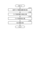
- FIG. 12 is a flowchart showing the operation of the wire electric discharge machining device 1000 according to the first embodiment during cutting.
- step S110 the parallel wire tension position measurement process is performed. That is, the parallel wire tension position measurement units 52a and 52b measure the distance L between the measurement reference plane set parallel to the virtual plane including the multiple cutting wire portions 1b as described above and the wire electrode 1 that constitutes the multiple cutting wire portions 1b.
- the parallel wire tension position measurement units 52a and 52b transmit information on the distance L, which is the measurement result, to the wire guide groove deviation detection unit 53.
- step S120 the wire guide groove deviation detection process is performed. That is, the wire guide groove deviation detection unit 53 detects the occurrence of a change in the distance L based on the measurement results in the parallel wire tension position measurement units 52a and 52b as described above. The wire guide groove deviation detection unit 53 calculates the change in the distance L as the difference ⁇ L. If the difference ⁇ L exceeds a predetermined standard, the wire guide groove deviation detection unit 53 transmits information on the difference ⁇ L to the wire condition determination unit 54.
- step S130 a wire status determination process is performed. That is, the wire status determination unit 54 determines whether at least one wire electrode 1 of the parallel wire portion 1a is in a wire-disconnected state in which it is disconnected from the wire guide groove 51c, or whether all wire electrodes 1 of the parallel wire portion 1a are in a wire-contact state in which they are in contact with the wire guide groove 51c, based on the detection result in the wire guide groove disconnection detection unit 53. If the wire status determination unit 54 determines that there has been a change in the tension state of the parallel wire portion 1a, it transmits parallel wire tension state information ps, which is state monitoring information, to the machining control device 31 of the control unit 300.
- parallel wire tension state information ps which is state monitoring information
- step S140 a machining control process is performed. That is, the machining control device 31 controls the stop or continuation of electric discharge machining based on the parallel wire tension state information ps, which is the judgment result of the wire state judgment unit 54.
- the machining control device 31 controls the continuation of electric discharge machining when the parallel wire tension state information ps is information indicating that there is no change in the tension state of the parallel wire portion 1a, i.e., the tension state of the cutting wire portion 1b.
- the machining control device 31 controls the stop of electric discharge machining when the parallel wire tension state information ps is information indicating that there is a change in the tension state of the parallel wire portion 1a, i.e., the tension state of the cutting wire portion 1b. That is, the machining control device 31 stops wire electric discharge machining at the same time as the occurrence of a parallel abnormality in the wire electrode 1.
- the wire electric discharge machining apparatus 1000 can detect a parallel abnormal state caused by the wire electrode 1 of the parallel wire portion 1a coming out of the wire guide groove 51c immediately after the parallel abnormal state occurs.
- the parallel abnormal state is an abnormality in which the multiple wire electrodes 1 of the cutting wire portion 1b, which are normally stretched in parallel and at equal intervals between a pair of wire parallel guide rollers 51a, 51b, are no longer stretched in parallel and at equal intervals.
- the wire electric discharge machining apparatus 1000 can accurately and early detect misalignment of the wire electrodes 1, and can accurately and early detect malfunctions caused by the misalignment of the wire electrodes 1.
- the wire electric discharge machining device 1000 can detect a parallel abnormality caused by some of the wire electrodes 1 of the parallel wire section 1a coming out of the wire guide groove 51c immediately after the abnormality occurs, and wire electric discharge machining is stopped as soon as the parallel abnormality occurs in the wire electrodes 1. This makes it possible to prevent a large amount of thin plate machining in which the plate thickness fluctuates midway due to electric discharge machining in which the parallel distance between the wire electrodes 1 of the parallel wire section 1a changes midway through cutting.
- the wire electric discharge machining apparatus 1000 stops the cutting process as soon as a parallel abnormality occurs in the wire electrode 1, the abnormal parts formed on the surface of the thin plate being cut can be kept to a minimum.
- the wire electric discharge machining apparatus 1000 can resume the cutting process from the machining stop position without the processing becoming unstable, improving the machining accuracy of the thin plate and improving the yield of the thin plate machining. Therefore, when cutting a semiconductor ingot, for example, the wire electric discharge machining apparatus 1000 can reduce wafer production costs without wasting expensive semiconductor crystals.
- the wire electric discharge machining device 1000 can stop cutting early when the parallel wire portion 1a is in an abnormal parallel state, preventing the formation of meandering portions in the machining groove of the workpiece W, which can reduce the amount of machining fluid supplied between the electrodes during cutting and hinder the discharge of machining waste, and can prevent breakage of the wire electrode 1.
- the wire electric discharge machining device 1000 has parallel wire tension position measuring units 52a, 52b equipped with at least one of an eddy current displacement sensor, a capacitance displacement sensor, an electrical current detection sensor, and a contact detection displacement sensor as a sensor, and measures the distance L using the sensor. This allows the wire electric discharge machining device 1000 to accurately and promptly detect a parallel abnormal state caused by a part of the wire electrode 1 of the parallel wire portion 1a coming out of the wire guide groove 51c immediately after the parallel abnormal state occurs.
- the wire electric discharge machining device 1000 has the effect of being able to accurately detect defects caused by misalignment of the wire electrode 1.
- the wire electric discharge machining device 1000 also has the effect of being able to uniformize the thickness of the thin plates that are cut and machined all at once from the workpiece W.
- Embodiment 2 In the second embodiment, other functions of the wire electric discharge machining apparatus 1000 will be described.
- the wire electric discharge machining apparatus 1000 which cuts and machines a thin plate all at once using the cutting wire portion 1b, supplies machining power from a machining power source 5 to each of the wire electrodes 1 of the parallel wire portion 1a that run in parallel at a predetermined interval.
- the machining power is supplied in pulses to each of the wire electrodes 1 of the parallel wire portion 1a, and is supplied only during a predetermined power supply time or voltage application time.
- a pause time during which no voltage is applied is set at a fixed time interval between voltage pulses.
- a method is used in which multiple power supply units are combined to enable power on and power off operations in a short period of time.
- the power supply unit may be damaged by an arm short circuit that causes the power to be turned on simultaneously within the power supply unit.
- a time called dead time is also set during which the voltage application of all combined power supplies is turned off.
- the pulse power supply from the machining power supply 5 to each power supply 11 or power supply units 6a, 6b is controlled by the machining control device 31 and the discharge waveform control device 32.
- a voltage pulse is applied between each wire electrode 1 of the parallel wire section 1a and the workpiece W via the power supply 11 connected to the machining power supply 5 by the power supply lines 12a and 12b, generating a discharge.
- the discharge waveform of the discharge generated between the wire electrode 1 of the cutting wire section 1b and the workpiece W varies according to the distance between the wire electrode 1 of the cutting wire section 1b and the workpiece W at the time the machining power supply is applied.
- the discharge waveform has a relatively low peak.
- the discharge waveform has a relatively high peak.
- the discharge waveform has a peak that is intermediate between the open state and the short state.
- the discharge voltage waveform during the pulse application time maintains almost the applied voltage level, and the discharge current waveform is at a low value.
- the discharge current may be detected as a small leakage current depending on the resistivity of the deionized water used as the machining fluid, i.e., the electrical conductivity of the deionized water, and the magnitude of the insulation resistance between adjacent feeders 11, the discharge current may be detected as a small leakage current.
- wire electric discharge machining apparatus 1000 which employs a method of performing electric discharge machining in deionized water
- the gap between the poles is insulated by the resistivity of the deionized water present between the poles.
- the resistivity between the poles decreases, and a discharge current with little resistance loss, or a current supplied from the machining power supply 5, flows between the poles. In this state, the discharge voltage drops significantly, and the discharge current has a waveform with a high peak.
- the "state where the wire electrode 1b and the workpiece W are at an appropriate inter-electrode distance" is classified as a state where the inter-electrode distance is neither the short-circuited nor open-circuited state described above. Since it is difficult to directly measure the inter-electrode distance during cutting, the wire electric discharge machining device 1000 constantly monitors the state of the generated discharge waveform.
- the wire electric discharge machining device 1000 detects a tendency in the discharge waveform to transition from a state where a discharge state that is neither an open state nor a short-circuited state continues to occur to an "open state” or a "short-circuited state," it maintains a stable discharge state by adjusting various conditions such as the applied voltage, machining current, discharge frequency, voltage application pulse time, and pulse application pause time.
- the wire electric discharge machining device 1000 monitors the discharge waveforms as described above, estimates the state of the gap between the wire electrode 1 of the cutting wire portion 1b and the workpiece W during cutting, and controls the cutting so that a large number of discharge waveforms that stabilize the cutting are generated.
- the machining control device 31 transmits command information to the discharge waveform control device 32 to instruct the oscillation frequency of the discharge pulse during discharge machining or the on-time and off-time of the discharge pulse, and controls the discharge energy supplied from the machining power source 5 to the gap between the wire electrode 1 of the cutting wire portion 1b and the workpiece W.
- the machining control device 31 transmits command information to the cutting stage drive control device 34 to instruct the machining feed speed, and controls the gap distance.
- This situation occurs when the machining current flowing through the cutting wire portion 1b when the cutting wire portion 1b is in complete contact with the workpiece W is not a pulse oscillation condition with a sufficient amount of heat to melt the wire electrode 1, or when a short circuit occurs between the cutting wire portion 1b and the workpiece W in a portion of the cutting wire portion 1b, but normal discharge occurs between the poles in other portions of the cutting wire portion 1b, and electric discharge cutting machining continues, and is caused by the inability to accurately observe or determine the situation in which the short circuit continues.
- the wire electrode 1 of the cutting wire portion 1b in contact with the workpiece W does not continue cutting beyond the position where the wire electrode 1 is short-circuited with the workpiece W.
- the wire electrode 1 of the cutting wire portion 1b that is short-circuited with the workpiece W continues to rise while being pulled up together with the workpiece W by the cutting feed stage 10 while in contact with the workpiece W.
- the wire electric discharge machining apparatus 1000 includes a wire contact machining state monitoring unit 500.
- FIG. 13 is a schematic diagram showing an example of the configuration of the wire contact machining state monitoring unit 500 of the wire electric discharge machining apparatus 1000 in the second embodiment.
- FIG. 13 shows a state in which the wire electrode 1 contacts the workpiece W and is short-circuited when wire electric discharge machining of the cylindrical workpiece W by the cutting wire portion 1b has progressed to a position about 1/2 the diameter of the workpiece W.
- the thin plate machining stabilization unit 70 is not shown in FIG. 13.
- the configuration of the wire tension state monitoring unit 400 is not shown in FIG. 13.
- the wire contact machining state monitoring unit 500 monitors the contact state between the parallel wire portion 1a and the nozzles 7a, 7b during cutting.
- FIG. 14 is a block diagram showing an example of the configuration of the control unit 300 and the wire contact machining state monitoring unit 500 provided in the wire electric discharge machining device 1000 in embodiment 2.
- the wire contact machining state monitoring unit 500 includes nozzle contact detection devices 75a, 75b, a wire contact detection circuit switching device 76, and a wire contact determination device 77.
- the nozzle contact detection devices 75a, 75b are connected to a wire contact detection circuit switching device 76 and the nozzles 7a, 7b.
- the wire contact detection circuit switching device 76 is connected to the nozzle contact detection devices 75a, 75b, the wire contact determination device 77, and the discharge waveform control device 32 of the control unit 300.
- the wire contact determination device 77 is connected to the nozzle contact detection devices 75a, 75b, the power supply lines 12a, 12b connecting the machining power supply 5 and the power supply 11, or to the machining power supply 5, and the machining control device 31 of the control unit 300. This constitutes the wire contact machining state monitoring unit 500.
- the nozzle contact detection devices 75a, 75b detect a characteristic value related to the potential difference between the nozzles 7a, 7b and the electron supply 11. Specifically, the nozzle contact detection devices 75a, 75b detect the current, voltage, or resistance value in the wire contact detection circuit. The nozzle contact detection devices 75a, 75b transmit information on the current, voltage, or resistance value in the wire contact detection circuit, which is the detection result, to the wire contact determination device 77.
- the wire contact detection circuit is composed of nozzle contact detection devices 75a, 75b, nozzles 7a, 7b, cutting wire portion 1b, power supply 11, power supply lines 12a, 12b, and wire contact determination device 77. Power is supplied to the wire contact detection circuit from a wire contact detection power supply 74 under the control of a wire contact detection circuit switching device 76.
- the wire contact detection circuit switching device 76 controls the opening and closing of the wire contact detection circuit. When the machining power supply is off and no machining voltage is applied between the poles, the wire contact detection circuit switching device 76 connects the wire contact detection circuit, i.e., closes the wire contact detection circuit. Also, when the machining power supply is on and a machining voltage is applied between the poles, the wire contact detection circuit switching device 76 disconnects the wire contact detection circuit, i.e., opens the wire contact detection circuit.
- the wire contact determination device 77 monitors changes in the current, voltage, or resistance in the wire contact detection circuit. When the wire contact determination device 77 detects a change in the current, voltage, or resistance in the wire contact detection circuit, it determines that short-circuit machining is continuing due to undetected contact between the wire electrode 1 of the parallel wire portion 1a and the nozzles 7a, 7b, and sends a signal uc indicating a contact machining state to the machining control device 31.
- the cutting wire portion 1b which is normally tensioned between a pair of parallel wire guide rollers 51a, 51b, is maintained in a linear tensioned state spaced apart from the workpiece W between the pair of parallel wire guide rollers 51a, 51b. Meanwhile, the wire electrode 1 of the cutting wire portion 1b, which is pulled up by the cutting feed stage 10 while in contact with the workpiece W, eventually comes into contact with the nozzles 7a, 7b with which it should not normally come into contact.
- Figure 13 shows the state in which the wire electrode 1 of the cutting wire portion 1b, which is pulled up by the cutting feed stage 10 while in contact with the workpiece W, comes into contact with the nozzles 7a, 7b with which it should not normally come into contact.
- FIG. 15 is a characteristic diagram showing the timing of switching between machining voltage application and wire contact detection in the wire electric discharge machining device 1000 in embodiment 2.
- the waveforms of the machining power supply application command pulse and the wire contact detection pulse are shown.
- the machining power supply application command pulse is a command pulse that the discharge waveform control device 32 uses to instruct the machining power supply 5 on the timing of application of the machining voltage.
- the wire contact detection pulse is a pulse power supply that supplies detection power to detect when the wire contact detection power supply 74 is in contact with the wire electrode 1 of the cutting wire portion 1b to the wire contact detection circuit.
- the wire contact detection pulse is a pulse that is oscillated in the opposite phase to the machining power supply application command pulse, which is a command pulse that commands the timing of application of the machining voltage to the machining gap by the machining power supply 5.
- the wire contact detection pulse can also be considered a wire contact detection circuit switching command pulse that switches the wire contact detection circuit between open and closed states.
- the machining power supply 5 When the machining power supply 5 receives a machining power supply application command pulse, which is a command pulse that commands the application timing of the machining voltage, from the discharge waveform control device 32, it supplies power to each of the power feeders 11 based on the machining power supply application command pulse, and supplies power individually to each of the parallel wire portions 1a. This applies a voltage between the cutting wire portion 1b and the workpiece W.
- a machining power supply application command pulse which is a command pulse that commands the application timing of the machining voltage
- the machining power supply application command pulse from the discharge waveform control device 32 When the machining power supply application command pulse from the discharge waveform control device 32 is in a LOW state, the period during which the machining power supply application command pulse is in a LOW state corresponds to the machining power supply off time P2.
- the machining power supply 5 is in a machining power off state in which no power is supplied to each of the power feeders 11, and no machining voltage is applied between the cutting wire portion 1b and the workpiece W.
- the machining power supply application command pulse goes to a HIGH state after the machining power supply off time P2 during which no machining voltage is applied, the period during which the machining power supply application command pulse is in a HIGH state becomes the machining power supply application time P1.
- the machining power supply is in an ON state in which power is supplied from the machining power supply 5 to each of the power feeders 11, and a machining voltage is applied between the electrodes of the cutting wire portion 1b and the workpiece W. If a discharge occurs between the electrodes while the machining power supply application command pulse is in a HIGH state, a machining current is supplied from the machining power supply 5 to the power feeders 11.
- a command pulse tc is sent from the discharge waveform control device 32 to the wire contact detection circuit switching device 76.
- the wire contact detection circuit switching device 76 connects the wire contact detection circuit during machining power off time P2 when no machining voltage is applied between the poles, i.e. when the machining power application command pulse sent from the discharge waveform control device 32 to the machining power supply 5 is in a LOW state.
- the wire contact detection circuit switching device 76 also disconnects the wire contact detection circuit during the machining power on time when the machining power application command pulse sent from the discharge waveform control device 32 to the machining power supply 5 is in a HIGH state and machining voltage is applied between the poles, i.e. during machining power application time P1.
- the machining power off time P2 corresponds to the period when the wire contact detection pulse is in a HIGH state.
- the period when the wire contact detection pulse is in a LOW state corresponds to detection power off time P3 during which no detection power is supplied to the wire contact detection circuit.
- the period when the wire contact detection pulse is in a HIGH state corresponds to short circuit detection time P4 during which the detection power is supplied to the wire contact detection circuit and the presence or absence of a short circuit between the workpiece W and the cutting wire portion 1b is detected.
- the period from time T11 onwards corresponds to short circuit processing duration P5 during which cutting processing is performed with the cutting wire portion 1b completely short circuited to the workpiece W.
- the waveform of the short circuit processing duration P5 during which the cutting process is performed with the cutting wire portion 1b completely short circuited with the workpiece W is present in the wire contact detection pulse.
- the wire contact detection pulse is a waveform in which the wire contact detection power supply 74 supplies detection power to the wire contact detection circuit to detect that the cutting wire portion 1b is in contact with the wire electrode 1.
- the configuration of the oscillator circuit and detection processing system would be simplified.
- the machining power supply is applied to the cutting wire 1b and the workpiece W in addition to the detection power supply, two types of power supply, the detection power supply and the machining power supply, are supplied to the cutting wire 1b and the workpiece W. For this reason, it is necessary to prevent a state in which two types of voltage, the detection power supply and the machining power supply, are applied simultaneously to the cutting wire 1b and the workpiece W.
- the wire electric discharge machining apparatus 1000 employs a method of applying a wire contact detection pulse to the cutting wire 1b and the workpiece W during the no-load time when the pulsed machining voltage is not being applied, as a measure to prevent two types of voltage, the detection power supply and the machining power supply, from being applied simultaneously to the cutting wire 1b and the workpiece W. If the cutting wire 1b is not in contact with the workpiece W, the wire contact detection circuit does not close, so no current supplied from the wire contact detection power supply 74 flows in the wire contact detection circuit and no voltage drop occurs, and the voltage applied to the wire contact detection circuit is in a high state, i.e., a HIGH state.
- the wire contact detection circuit is closed via the conductive workpiece W.
- the potential detected by the nozzle contact detection devices 75a, 75b is lower than when the cutting wire portion 1b and the workpiece W are not in contact, i.e., it is in a LOW state.
- the wire electric discharge machining device 1000 it is possible to determine whether the cutting wire portion 1b and the workpiece W are in contact or not in contact with each other based on the voltage state detected by the nozzle contact detection devices 75a, 75b, for example, based on whether the voltage pulse applied to the wire contact detection circuit is in a HIGH or LOW state, as shown in FIG. 15.
- the cutting wire portion 1b does not come into contact with the nozzles 7a, 7b, so the wire contact detection circuit is open.
- the cutting stage drive control device 34 continues to feed the cutting wire, so that the pulled-up cutting wire portion 1b comes into contact with the metal nozzles 7a, 7b, causing the wire contact detection circuit to close.
- the wire contact determination device 77 detects a change in the current value, voltage value, or resistance value in the wire contact detection circuit when the wire contact detection circuit is connected by the wire contact detection circuit switching device 76.
- the wire contact determination device 77 detects a change in the current value, voltage value, or resistance value of the wire contact detection circuit by comparing the current value, voltage value, or resistance value in the wire contact detection circuit detected when the wire contact detection circuit is connected by the wire contact detection circuit switching device 76 with a predetermined current value, voltage value, or resistance value determination reference value.
- the predetermined current, voltage or resistance reference value is the current, voltage or resistance value of the wire contact detection circuit when the cutting wire portion 1b comes into contact with the workpiece W and is pulled up and in contact with the metal nozzles 7a and 7b.
- the wire contact determination device 77 determines that there is a change in the current value, voltage value, or resistance value, and determines that a change in the current value, voltage value, or resistance value of the wire contact detection circuit has been detected. If the detected current value, voltage value, or resistance value in the wire contact detection circuit does not exceed the corresponding reference value, the wire contact determination device 77 determines that there is no change in the current value, voltage value, or resistance value, and determines that no change in the current value, voltage value, or resistance value of the wire contact detection circuit has been detected.
- the wire contact determination device 77 When the wire contact determination device 77 detects a change in the current value, voltage value, or resistance value of the wire contact detection circuit, it determines that the short-circuit machining is continuing, in which cutting is being performed in a short circuit state between the workpiece W and the cutting wire portion 1b, due to no contact detection, in which no contact is detected between the wire electrode 1 of the parallel wire portion 1a and the nozzles 7a, 7b.
- the short-circuit machining continuing state can be said to be a contact machining state, in which cutting is being performed in a state in which the workpiece W and the cutting wire portion 1b are in contact.
- the wire contact determination device 77 then transmits a signal uc indicating the contact machining state to the machining control device 31.
- the machining control device 31 When the machining control device 31 receives the signal uc indicating the contact machining state, it instructs the discharge waveform control device 32 to stop oscillating the machining power supply 5, the wire travel control device 35 to stop wire travel, and the cutting stage drive control device 34 to stop the cutting feed stage 10 based on the signal uc. That is, based on the signal uc, the machining control device 31 stops the application of voltage to the gap, stops the travel of the wire electrode 1, and stops the movement of the cutting feed stage 10 and the workpiece W, thereby stopping the cutting process.
- the wire contact detection power supply 74 applies the detection power supply to the wire contact detection circuit so that it is not applied simultaneously with the machining power supply supplied between the poles from the machining power supply 5. In other words, the wire contact detection power supply 74 supplies the wire contact power supply to the wire contact detection circuit with a wire contact detection pulse.
- the machining power supply will also be connected to the wire contact detection circuit from the power supply 11 or the power supply lines 12a and 12b, which may damage the devices that make up the wire contact detection circuit.
- the power supply for detecting the machining power application command pulse will be applied to the poles, which may cause the electric discharge machining to become unstable.
- the wire contact detection power supply 74 not only oscillates with an antiphase pulse to the machining power supply application command pulse, but also sets periods during which neither the machining power supply application command pulse nor the wire contact detection pulse are in the ON state, namely, a period of several hundred nanoseconds ⁇ t1 immediately after the machining power supply application command pulse changes from HIGH to LOW, and a period of several hundred nanoseconds ⁇ t2 immediately before the pulse changes from LOW to HIGH, as shown in FIG. 15.
- the machining power supply application command pulse sent from the discharge waveform control device 32 to the machining power supply 5 is also sent to the wire contact detection circuit switching device 76.
- the wire contact detection circuit switching device 76 refers to the machining power supply application command pulse and opens and closes the wire contact detection circuit based on the timing of the application of the pulsed voltage from the machining power supply 5 to the power supply 11.
- FIG. 16 is a schematic diagram showing an example of a state in which the parallel wire portion 1a comes off the wire guide groove 51c in the wire parallel guide roller 51a of the wire electric discharge machining device 1000 in the second embodiment.
- FIG. 16 shows a vertical section through the rotation axis 51a2 of the wire parallel guide roller 51a, for the parallel wire portion 1a and the wire parallel guide roller 51a stretched between the nozzle 7a and the wire parallel guide rollers 51a and 51b.
- FIG. 16 also shows a state in which the parallel wire portion 1a stretched on the wire guide groove 51c is lifted up by continuing cutting processing with a part of the wire electrode 1 of the parallel wire portion 1a in contact with the workpiece W, and then comes into contact with the nozzle 7a, and the nozzle 7a is cut off by continuing cutting processing.
- the parallel wire portion 1a coming off the wire guide groove 51c is shown by a white circle.
- FIG. 17 is a conceptual diagram showing detection values corresponding to the wire-disconnected state in FIG. 16 and state determinations corresponding to the detection values.
- Detection value D is the current value, voltage value, or resistance value in the wire contact detection circuit when the wire contact detection circuit is connected by wire contact detection circuit switching device 76.
- FIG. 17 shows a schematic diagram of the detection values used to show the monitoring status of the behavior of the parallel wire portion 1a that has come off the wire guide groove 51c in FIG. 16 by the wire contact machining state monitoring unit 500 of the wire electric discharge machining device 1000.
- the floating wire electrode 1 will eventually come into contact with the nozzle 7a (state C). If the cutting is continued, the wire electrode 1 in contact with the nozzle 7a will cut the nozzle 7a while rubbing it as it travels, and a cutting groove Wz will be formed in the nozzle 7a. If state C continues, a break in the wire electrode 1 will occur.
- the process progresses from state A, which is a steady state in which there is no abnormality in the wire tension state, through state B to state B, in which the wire electrode 1 contacts the nozzle 7a.
- state A which is a steady state in which there is no abnormality in the wire tension state
- state B in which the wire electrode 1 contacts the nozzle 7a.
- the wire contact determination device 77 detects the occurrence of state C, in which the wire is in contact with the nozzle 7a, as the detection value D changes from detection value D1 in the steady state to detection value D2.
- the wire contact determination device 77 detects the occurrence of state C based on the detection value in the nozzle contact detection device 75a.
- the wire contact determination device 77 transmits a signal uc indicating the contact machining state to the machining control device 31. Based on the signal uc, the machining control device 31 instructs the discharge waveform control device 32 to stop the oscillation of the machining power supply 5, the wire travel control device 35 to stop the wire travel, and the cutting stage drive control device 34 to stop the cutting feed stage 10.
- the machining control device 31 when the machining control device 31 receives a signal uc indicating the contact machining state from the wire contact determination device 77, it instructs the discharge waveform control device 32 to temporarily suspend the oscillation of the machining power supply 5 or to control the oscillation frequency to rapidly reduce the oscillation frequency of the machining power supply 5, or instructs the wire travel control device 35 to reverse the feed direction of the wire electrode 1 by the cutting stage drive control device 34 from the cutting progress direction and to rapidly retract the cutting feed stage 10 (state D in Figures 16 and 17). That is, based on the signal uc, the machining control device 31 controls the retraction operation to eliminate the short circuit by reversing the feed direction of the cutting stage drive control device 34 from the cutting progress direction. This allows the wire electric discharge machining device 1000 to return the wire electrode 1 that has become abnormally stretched back into the wire guide groove 51c without interrupting the cutting process.
- the machining control device 31 does not perform the above-mentioned retraction operation to eliminate the short circuit based on the signal uc, it stops the power supply to all parallel wire portions 1a and stops the cutting process. This allows the machining control device 31 to stop the cutting process at the same time as the occurrence of a parallel abnormality in the wire electrode 1.
- the second embodiment it is possible to detect when a part of the wire electrode 1 of the parallel wire portion 1a comes out of the wire guide groove 51c and comes into contact with the nozzles 7a, 7b, and to stop the cutting process at the point when the wire electrode 1 comes into contact with the nozzles 7a, 7b. As a result, according to the second embodiment, it is possible to prevent damage to peripheral devices constituting the wire electric discharge machining device 1000, such as the nozzles 7a, 7b, caused by friction of the wire electrode 1.
- the wire electrode 1 that has come out of the wire guide groove 51c comes into contact with the nozzles 7a, 7b
- the wire electrode 1 is prevented from being broken by the oscillation control of the machining power source 5. That is, when the wire electrode 1 that has come out of the wire guide groove 51c comes into contact with the nozzles 7a, 7b, the wire electric discharge machining device 1000 performs control to temporarily suspend the oscillation of the machining power source 5, or performs oscillation frequency control to suddenly lower the oscillation frequency of the machining power source 5, thereby preventing the wire electrode 1 from being broken due to the continuation of cutting in a contact machining state.
- the cutting feed stage 10 is driven and controlled to retract the wire electrode 1 from the wire contact state, so that the wire electrode 1 that has become abnormally stretched can be returned to the wire guide groove 51c without interrupting the cutting process.
- the wire electric discharge machining apparatus 1000 stops the cutting process at the same time as the occurrence of a parallel abnormality in the wire electrode 1, so that the machining in the state where the wire electrode 1 is in contact can be kept to a minimum, and the abnormal part formed on the surface of the thin plate during cutting can be kept to a minimum.
- the wire electric discharge machining apparatus 1000 can resume machining after repairing the tension state of the wire electrode 1 in the tension abnormality state and the power supply state to the wire electrode 1, and can resume cutting from the machining stop position without machining instability, improving the machining accuracy of the thin plate and improving the yield of thin plate machining. Therefore, the wire electric discharge machining apparatus 1000 can reduce wafer production costs, for example, when cutting a semiconductor ingot, without wasting expensive semiconductor crystals.
- the wire electric discharge machining device 1000 can improve the yield of thin plate machining without wasting expensive semiconductor crystals, and reduce wafer production costs.
- the second embodiment it is possible to obtain a wire electric discharge machining apparatus 1000 that can accurately detect defects caused by misalignment of the wire electrode 1. Furthermore, according to the second embodiment, it is possible to uniformize the thickness of the thin plates that are cut and machined in one go from the workpiece W. Furthermore, according to the second embodiment, it is possible to prevent damage to the devices included in the wire electric discharge machining apparatus 1000 that may be caused by a short-circuited wire electrode 1.
- the control unit 80 according to the first and second embodiments corresponds to the control unit 300 and the wire tension state monitoring unit 400 in the first and second embodiments, and the wire contact processing state monitoring unit 500 in the second embodiment.
- Each function of the control unit 80 according to the first and second embodiments is realized by a processing circuit.
- the processing circuit may be dedicated hardware, or may be a processing device that executes a program stored in a storage device.
- the processing circuit When the processing circuit is dedicated hardware, the processing circuit may be a single circuit, a composite circuit, a programmed processor, a parallel programmed processor, an application specific integrated circuit, a field programmable gate array, or a combination of these.
- Figure 18 is a diagram showing a configuration in which the functions of the control unit in the first and second embodiments are realized by hardware.
- a logic circuit 81a that realizes the functions of the control unit 80 is incorporated in the processing circuit 81.
- the processing circuit 81 is a processing device, the functions of the control unit 80 are realized by software, firmware, or a combination of software and firmware.
- the processing circuit 81 has a processor 811 that executes the program 81b, a random access memory 812 that the processor 811 uses as a work area, and a storage device 813 that stores the program 81b.
- the processor 811 deploys the program 81b stored in the storage device 813 on the random access memory 812 and executes it, thereby realizing the functions of the control unit 80.
- the software or firmware is written in a programming language and stored in the storage device 813.
- the processor 811 can be exemplified by a central processing unit, but is not limited to this.
- the storage device 813 can be a semiconductor memory such as a RAM (Random Access Memory), a ROM (Read Only Memory), a flash memory, an EPROM (Erasable Programmable Read Only Memory), or an EEPROM (registered trademark) (Electrically Erasable Programmable Read Only Memory).
- the semiconductor memory may be a non-volatile memory or a volatile memory.
- the storage device 813 may be a magnetic disk, a flexible disk, an optical disk, a compact disk, a mini disk, or a DVD (Digital Versatile Disc).
- the processor 811 may output data such as the results of calculations to the storage device 813 for storage, or may store the data in an auxiliary storage device (not shown) via the random access memory 812.
- the functions of the control unit 80 can be realized by a microcomputer.
- the processing circuit 81 realizes the functions of the control unit 80 by reading and executing the program 81b stored in the storage device 813. It can also be said that the program 81b causes the computer to execute the procedures and methods for realizing the functions of the control unit 80.
- processing circuit 81 may implement some of the functions of the control unit 80 using dedicated hardware, and some of the functions of the control unit 80 using software or firmware.
- the processing circuit 81 can realize each of the above-mentioned functions through hardware, software, firmware, or a combination of these.
Landscapes
- Chemical & Material Sciences (AREA)
- Chemical Kinetics & Catalysis (AREA)
- Electrochemistry (AREA)
- Engineering & Computer Science (AREA)
- Mechanical Engineering (AREA)
- Electrical Discharge Machining, Electrochemical Machining, And Combined Machining (AREA)
Priority Applications (5)
| Application Number | Priority Date | Filing Date | Title |
|---|---|---|---|
| JP2023557457A JP7391282B1 (ja) | 2023-05-23 | 2023-05-23 | ワイヤ放電加工装置、ワイヤ放電加工方法およびウエハの製造方法 |
| CN202380098426.2A CN121152700A (zh) | 2023-05-23 | 2023-05-23 | 线放电加工装置、线放电加工方法及晶片的制造方法 |
| DE112023006392.3T DE112023006392T5 (de) | 2023-05-23 | 2023-05-23 | Draht-elektrische entladungsbearbeitungsvorrichtung,draht-elektrische entladungsbearbeitungsverfahren undwafer-herstellungsverfahren |
| PCT/JP2023/019205 WO2024241506A1 (ja) | 2023-05-23 | 2023-05-23 | ワイヤ放電加工装置、ワイヤ放電加工方法およびウエハの製造方法 |
| TW113115962A TWI888115B (zh) | 2023-05-23 | 2024-04-29 | 線切割放電加工裝置、線切割放電加工方法及晶圓之製造方法 |
Applications Claiming Priority (1)
| Application Number | Priority Date | Filing Date | Title |
|---|---|---|---|
| PCT/JP2023/019205 WO2024241506A1 (ja) | 2023-05-23 | 2023-05-23 | ワイヤ放電加工装置、ワイヤ放電加工方法およびウエハの製造方法 |
Publications (1)
| Publication Number | Publication Date |
|---|---|
| WO2024241506A1 true WO2024241506A1 (ja) | 2024-11-28 |
Family
ID=89023124
Family Applications (1)
| Application Number | Title | Priority Date | Filing Date |
|---|---|---|---|
| PCT/JP2023/019205 Ceased WO2024241506A1 (ja) | 2023-05-23 | 2023-05-23 | ワイヤ放電加工装置、ワイヤ放電加工方法およびウエハの製造方法 |
Country Status (5)
| Country | Link |
|---|---|
| JP (1) | JP7391282B1 (https=) |
| CN (1) | CN121152700A (https=) |
| DE (1) | DE112023006392T5 (https=) |
| TW (1) | TWI888115B (https=) |
| WO (1) | WO2024241506A1 (https=) |
Citations (4)
| Publication number | Priority date | Publication date | Assignee | Title |
|---|---|---|---|---|
| JPH1055508A (ja) * | 1996-08-08 | 1998-02-24 | Yamaha Corp | 薄膜磁気ヘッド用ウェハの切断方法およびその装置 |
| JP2012061550A (ja) * | 2010-09-15 | 2012-03-29 | Tokyo Cathode Laboratory Co Ltd | マルチワイヤ放電加工装置及びマルチワイヤ放電加工方法並びに炭化ケイ素板の製造方法 |
| WO2012070167A1 (ja) * | 2010-11-24 | 2012-05-31 | 三菱電機株式会社 | ワイヤ放電加工装置および半導体ウエハ製造方法 |
| JP2014168832A (ja) * | 2013-03-05 | 2014-09-18 | Canon Marketing Japan Inc | 加工装置、加工方法 |
Family Cites Families (4)
| Publication number | Priority date | Publication date | Assignee | Title |
|---|---|---|---|---|
| JP5786917B2 (ja) * | 2013-01-29 | 2015-09-30 | キヤノンマーケティングジャパン株式会社 | ワイヤ放電加工装置およびワイヤ放電加工方法。 |
| DE112014006901B4 (de) * | 2014-09-24 | 2019-12-19 | Mitsubishi Electric Corporation | Elektrische Drahterodiervorrichtung und Verfahren zur Herstellung eines Halbleiterwafers |
| JP6537440B2 (ja) | 2015-11-16 | 2019-07-03 | 株式会社ディスコ | マルチワイヤ放電加工装置 |
| DE112020007596T5 (de) * | 2020-09-10 | 2023-06-29 | Mitsubishi Electric Corporation | Drahtfunkenbearbeitungseinrichtung und verfahren zum herstellen von halbleiterwafern |
-
2023
- 2023-05-23 WO PCT/JP2023/019205 patent/WO2024241506A1/ja not_active Ceased
- 2023-05-23 DE DE112023006392.3T patent/DE112023006392T5/de active Pending
- 2023-05-23 JP JP2023557457A patent/JP7391282B1/ja active Active
- 2023-05-23 CN CN202380098426.2A patent/CN121152700A/zh active Pending
-
2024
- 2024-04-29 TW TW113115962A patent/TWI888115B/zh active
Patent Citations (4)
| Publication number | Priority date | Publication date | Assignee | Title |
|---|---|---|---|---|
| JPH1055508A (ja) * | 1996-08-08 | 1998-02-24 | Yamaha Corp | 薄膜磁気ヘッド用ウェハの切断方法およびその装置 |
| JP2012061550A (ja) * | 2010-09-15 | 2012-03-29 | Tokyo Cathode Laboratory Co Ltd | マルチワイヤ放電加工装置及びマルチワイヤ放電加工方法並びに炭化ケイ素板の製造方法 |
| WO2012070167A1 (ja) * | 2010-11-24 | 2012-05-31 | 三菱電機株式会社 | ワイヤ放電加工装置および半導体ウエハ製造方法 |
| JP2014168832A (ja) * | 2013-03-05 | 2014-09-18 | Canon Marketing Japan Inc | 加工装置、加工方法 |
Also Published As
| Publication number | Publication date |
|---|---|
| DE112023006392T5 (de) | 2026-03-05 |
| JP7391282B1 (ja) | 2023-12-04 |
| JPWO2024241506A1 (https=) | 2024-11-28 |
| CN121152700A (zh) | 2025-12-16 |
| TWI888115B (zh) | 2025-06-21 |
| TW202446523A (zh) | 2024-12-01 |
Similar Documents
| Publication | Publication Date | Title |
|---|---|---|
| JP5490255B2 (ja) | ワイヤ放電加工装置および半導体ウエハ製造方法 | |
| US20200316817A1 (en) | Method and apparatus for resuming the wire sawing process of a workpiece after an unplanned interruption | |
| JP6178584B2 (ja) | ダイヤモンドワイヤソーデバイスおよび方法 | |
| EP2954965A1 (en) | Method and system for sawing an ingot | |
| KR20090055003A (ko) | 절단방법 | |
| JP6651064B1 (ja) | ワイヤ放電加工機 | |
| CN115023328A (zh) | 用于在一系列分离工艺期间通过线锯从工件分离多个晶片的方法 | |
| TWI424897B (zh) | 線切割放電加工方法與裝置、及線切割放電加工用程式製作裝置、以及記錄有製作線切割放電加工用程式的程式之可電腦讀取記錄媒體 | |
| JP5693697B2 (ja) | ワイヤソーで加工物を複数のウェハに切断するための、中断されたプロセスを再開するための方法 | |
| US10189101B2 (en) | Wire electric discharge machine with automatic wire connecting function | |
| JP7343328B2 (ja) | ワイヤ放電加工機および制御方法 | |
| WO2024241506A1 (ja) | ワイヤ放電加工装置、ワイヤ放電加工方法およびウエハの製造方法 | |
| JP6072718B2 (ja) | ワイヤ放電加工装置、薄板の製造方法および半導体ウエハの製造方法 | |
| JP2000141220A (ja) | ワイヤソーのワークプレート温度制御装置 | |
| CN117157165B (zh) | 线放电加工装置及线放电加工方法 | |
| JP7580681B1 (ja) | ワイヤ放電加工装置、ワイヤ放電加工方法、およびウエハの製造方法 | |
| WO2012089243A1 (en) | Wire saw device, method of operating thereof | |
| JP2001087946A (ja) | ワイヤ放電加工機の加工液供給制御方法 | |
| JP7282277B1 (ja) | ワイヤ放電加工装置、ワイヤ放電加工方法およびウエハの製造方法 | |
| US10144077B2 (en) | Wire electrical discharge apparatus and initial hole machining method | |
| JP2000094296A (ja) | ワイヤソーの熱交換装置 | |
| EP4389335B1 (en) | Method for wire electrical discharge machining | |
| JPWO2024241506A5 (https=) | ||
| US20220001473A1 (en) | Wire management method for high-speed wire cutting | |
| CN108568740B (zh) | 线状锯及线状锯的工件切断加工方法 |
Legal Events
| Date | Code | Title | Description |
|---|---|---|---|
| WWE | Wipo information: entry into national phase |
Ref document number: 2023557457 Country of ref document: JP |
|
| 121 | Ep: the epo has been informed by wipo that ep was designated in this application |
Ref document number: 23938471 Country of ref document: EP Kind code of ref document: A1 |
|
| WWE | Wipo information: entry into national phase |
Ref document number: 112023006392 Country of ref document: DE |
|
| WWP | Wipo information: published in national office |
Ref document number: 112023006392 Country of ref document: DE |