WO2023233554A1 - 基板収納容器及び蓋体側基板支持部 - Google Patents
基板収納容器及び蓋体側基板支持部 Download PDFInfo
- Publication number
- WO2023233554A1 WO2023233554A1 PCT/JP2022/022223 JP2022022223W WO2023233554A1 WO 2023233554 A1 WO2023233554 A1 WO 2023233554A1 JP 2022022223 W JP2022022223 W JP 2022022223W WO 2023233554 A1 WO2023233554 A1 WO 2023233554A1
- Authority
- WO
- WIPO (PCT)
- Prior art keywords
- lid
- substrates
- substrate
- opening
- container
- Prior art date
- Legal status (The legal status is an assumption and is not a legal conclusion. Google has not performed a legal analysis and makes no representation as to the accuracy of the status listed.)
- Ceased
Links
Images


Classifications
-
- H—ELECTRICITY
- H10—SEMICONDUCTOR DEVICES; ELECTRIC SOLID-STATE DEVICES NOT OTHERWISE PROVIDED FOR
- H10P—GENERIC PROCESSES OR APPARATUS FOR THE MANUFACTURE OR TREATMENT OF DEVICES COVERED BY CLASS H10
- H10P72/00—Handling or holding of wafers, substrates or devices during manufacture or treatment thereof
- H10P72/10—Handling or holding of wafers, substrates or devices during manufacture or treatment thereof using carriers specially adapted therefor, e.g. front opening unified pods [FOUP]
- H10P72/19—Handling or holding of wafers, substrates or devices during manufacture or treatment thereof using carriers specially adapted therefor, e.g. front opening unified pods [FOUP] closed carriers
- H10P72/1921—Handling or holding of wafers, substrates or devices during manufacture or treatment thereof using carriers specially adapted therefor, e.g. front opening unified pods [FOUP] closed carriers characterised by substrate supports
-
- H—ELECTRICITY
- H10—SEMICONDUCTOR DEVICES; ELECTRIC SOLID-STATE DEVICES NOT OTHERWISE PROVIDED FOR
- H10P—GENERIC PROCESSES OR APPARATUS FOR THE MANUFACTURE OR TREATMENT OF DEVICES COVERED BY CLASS H10
- H10P72/00—Handling or holding of wafers, substrates or devices during manufacture or treatment thereof
- H10P72/10—Handling or holding of wafers, substrates or devices during manufacture or treatment thereof using carriers specially adapted therefor, e.g. front opening unified pods [FOUP]
-
- H—ELECTRICITY
- H10—SEMICONDUCTOR DEVICES; ELECTRIC SOLID-STATE DEVICES NOT OTHERWISE PROVIDED FOR
- H10P—GENERIC PROCESSES OR APPARATUS FOR THE MANUFACTURE OR TREATMENT OF DEVICES COVERED BY CLASS H10
- H10P72/00—Handling or holding of wafers, substrates or devices during manufacture or treatment thereof
- H10P72/10—Handling or holding of wafers, substrates or devices during manufacture or treatment thereof using carriers specially adapted therefor, e.g. front opening unified pods [FOUP]
- H10P72/14—Vertical carrier comprising wall type elements whereby the substrates are horizontally supported, e.g. comprising sidewalls
-
- H—ELECTRICITY
- H10—SEMICONDUCTOR DEVICES; ELECTRIC SOLID-STATE DEVICES NOT OTHERWISE PROVIDED FOR
- H10P—GENERIC PROCESSES OR APPARATUS FOR THE MANUFACTURE OR TREATMENT OF DEVICES COVERED BY CLASS H10
- H10P72/00—Handling or holding of wafers, substrates or devices during manufacture or treatment thereof
- H10P72/10—Handling or holding of wafers, substrates or devices during manufacture or treatment thereof using carriers specially adapted therefor, e.g. front opening unified pods [FOUP]
- H10P72/19—Handling or holding of wafers, substrates or devices during manufacture or treatment thereof using carriers specially adapted therefor, e.g. front opening unified pods [FOUP] closed carriers
- H10P72/1918—Handling or holding of wafers, substrates or devices during manufacture or treatment thereof using carriers specially adapted therefor, e.g. front opening unified pods [FOUP] closed carriers characterised by coupling elements, kinematic members, handles or elements to be externally gripped
-
- H—ELECTRICITY
- H10—SEMICONDUCTOR DEVICES; ELECTRIC SOLID-STATE DEVICES NOT OTHERWISE PROVIDED FOR
- H10P—GENERIC PROCESSES OR APPARATUS FOR THE MANUFACTURE OR TREATMENT OF DEVICES COVERED BY CLASS H10
- H10P72/00—Handling or holding of wafers, substrates or devices during manufacture or treatment thereof
- H10P72/10—Handling or holding of wafers, substrates or devices during manufacture or treatment thereof using carriers specially adapted therefor, e.g. front opening unified pods [FOUP]
- H10P72/19—Handling or holding of wafers, substrates or devices during manufacture or treatment thereof using carriers specially adapted therefor, e.g. front opening unified pods [FOUP] closed carriers
- H10P72/1922—Handling or holding of wafers, substrates or devices during manufacture or treatment thereof using carriers specially adapted therefor, e.g. front opening unified pods [FOUP] closed carriers characterised by the construction of the closed carrier
-
- H—ELECTRICITY
- H10—SEMICONDUCTOR DEVICES; ELECTRIC SOLID-STATE DEVICES NOT OTHERWISE PROVIDED FOR
- H10P—GENERIC PROCESSES OR APPARATUS FOR THE MANUFACTURE OR TREATMENT OF DEVICES COVERED BY CLASS H10
- H10P72/00—Handling or holding of wafers, substrates or devices during manufacture or treatment thereof
- H10P72/70—Handling or holding of wafers, substrates or devices during manufacture or treatment thereof for supporting or gripping
- H10P72/76—Handling or holding of wafers, substrates or devices during manufacture or treatment thereof for supporting or gripping using mechanical means, e.g. clamps or pinches
- H10P72/7604—Handling or holding of wafers, substrates or devices during manufacture or treatment thereof for supporting or gripping using mechanical means, e.g. clamps or pinches the wafers being placed on a susceptor, stage or support
- H10P72/7614—Handling or holding of wafers, substrates or devices during manufacture or treatment thereof for supporting or gripping using mechanical means, e.g. clamps or pinches the wafers being placed on a susceptor, stage or support characterised by a plurality of individual support members, e.g. support posts or protrusions
-
- H—ELECTRICITY
- H10—SEMICONDUCTOR DEVICES; ELECTRIC SOLID-STATE DEVICES NOT OTHERWISE PROVIDED FOR
- H10P—GENERIC PROCESSES OR APPARATUS FOR THE MANUFACTURE OR TREATMENT OF DEVICES COVERED BY CLASS H10
- H10P72/00—Handling or holding of wafers, substrates or devices during manufacture or treatment thereof
- H10P72/70—Handling or holding of wafers, substrates or devices during manufacture or treatment thereof for supporting or gripping
- H10P72/76—Handling or holding of wafers, substrates or devices during manufacture or treatment thereof for supporting or gripping using mechanical means, e.g. clamps or pinches
- H10P72/7604—Handling or holding of wafers, substrates or devices during manufacture or treatment thereof for supporting or gripping using mechanical means, e.g. clamps or pinches the wafers being placed on a susceptor, stage or support
- H10P72/7624—Handling or holding of wafers, substrates or devices during manufacture or treatment thereof for supporting or gripping using mechanical means, e.g. clamps or pinches the wafers being placed on a susceptor, stage or support characterised by the mechanical construction of the susceptor, stage or support
Definitions
- the present invention relates to a substrate storage container and a lid-side substrate support part used when storing, storing, transporting, etc. substrates made of semiconductor wafers and the like.
- Patent Document 1 As a substrate storage container for accommodating substrates made of semiconductor wafers and transporting them in a process within a factory, a structure comprising a container body and a lid body is conventionally known (for example, Patent Document 1 , see Patent Document 2).
- One end of the container body has an opening periphery in which a container body opening is formed.
- the other end of the container body has a closed cylindrical wall.
- a substrate storage space is formed within the container body.
- the substrate storage space is surrounded by a wall and is capable of accommodating substrates.
- the lid is removable from the opening periphery and can close the opening of the container body.
- the side substrate supports are provided on the wall portion in pairs in the substrate storage space.
- the side substrate support section is capable of supporting the edges of the substrates in a state where adjacent substrates are spaced apart from each other at a predetermined interval and arranged in parallel when the opening of the container main body is not closed by the lid.
- a front retainer is provided in the portion of the lid that faces the substrate storage space when the container main body opening is closed.
- the front retainer can support the edge of the substrate when the opening of the container body is closed by the lid.
- a back side substrate support part is provided on the wall part so as to be paired with the front retainer.
- the back substrate support section can support the edge of the substrate.
- the back side substrate support section works with the front retainer to support the substrates when the container main body opening is closed by the lid, so that adjacent substrates are spaced apart from each other at a predetermined interval and arranged in parallel. Hold the board in this position.
- substrates that have been thinned by polishing or the like may be stored in substrate storage containers and transported.
- the board may be bent due to its own weight, vibration during transportation, slight impact, etc., leading to breakage or damage.
- a configuration can be considered in which the pitch of the supports that support multiple substrates in the substrate storage container is widened to avoid such breakage and damage.
- An object of the present invention is to provide a substrate storage container and a lid-side substrate support part that can hold a thin substrate without breakage or damage when the thin substrate is bent by its own weight or impact.
- the present invention includes a cylindrical wall portion formed with a container body opening at one end and closed at the other end, and a plurality of substrates can be accommodated by the inner surface of the wall portion, and the container body opening is provided with a cylindrical wall portion.
- the edge of the plurality of substrates is a supportable lid-side substrate support part;
- the lid-side substrate support part is disposed in a pair with the lid-side substrate support part in the substrate storage space and is capable of supporting edges of the plurality of substrates;
- a back side substrate support part that cooperates with the lid side substrate support part to support the plurality of substrates with edges of the plurality of substrates aligned in parallel when the main body opening is closed;
- the lid-side substrate support part has a support flat surface that supports the substrate by coming into contact with the peripheral surface of each edge of the plurality of substrates, and the lid-side substrate support part has a support flat surface that supports the substrate by contacting the peripheral surface of the edge of each of the plurality of substrates, and
- the support flat surface that abuts the circumferential surface of each edge of the substrate storage container has overlapped portions facing each other in
- a plurality of supporting flat surfaces are provided, one for each peripheral surface of the edge of each of the plurality of substrates.
- the support flat surface is located at the free end of the cantilever spring.
- the support flat surface abuts on the one substrate at one point on the peripheral surface of the front edge of the one substrate.
- the plurality of substrates are stored in parallel in the substrate storage space, and the length of the support flat surface in the parallel direction of the plurality of substrates is 5 mm or more.
- the area of the support flat surface is preferably 50 mm 2 or more.
- the present invention includes a cylindrical wall portion formed with a container body opening at one end and closed at the other end, and a plurality of substrates can be accommodated by the inner surface of the wall portion, and the container body opening a container body in which a substrate storage space communicating with the container body is formed; a lid body that is removable from the opening of the container body and capable of closing the opening of the container body; The edges of the plurality of substrates are arranged at a portion facing the substrate storage space when the container main body opening is closed by the lid, and are arranged at the edges of the plurality of substrates when the container main body opening is closed by the lid.
- a lid body-side substrate support part that can support the parts; and a lid body side substrate support part that is arranged in the substrate storage space so as to form a pair with the lid body side substrate support part and can support the edges of the plurality of substrates; a back side substrate support part that cooperates with the lid side substrate support part to support the plurality of substrates with edges of the plurality of substrates aligned in parallel when the container main body opening is closed;
- a lid-side substrate support portion of a substrate storage container comprising: a supporting flat surface that supports the substrate by contacting a circumferential surface of each edge of the plurality of substrates; The support flat surface that contacts the circumferential surface of each edge of the adjacent substrates relates to a lid-side substrate support portion having an overlapping portion facing in a direction parallel to the upper surface of the substrate.
- a plurality of supporting flat surfaces are provided, one for each peripheral surface of the edge of each of the plurality of substrates.
- the support flat surface is located at the free end of the cantilever spring.
- the support flat surface abuts the one substrate at one point on the peripheral surface of the front edge of the one substrate.
- the plurality of substrates are stored in parallel in the substrate storage space, and the length of the support flat surface in the parallel direction of the plurality of substrates is 5 mm or more.
- the area of the support flat surface is preferably 50 mm 2 or more.
- the present invention it is possible to provide a substrate storage container and a lid-side substrate support portion that can hold a thin substrate without breakage or damage when the thin substrate is bent by its own weight or impact.
- FIG. 2 is an exploded perspective view showing a plurality of substrates stored in a substrate storage container according to an embodiment of the present invention.
- FIG. 1 is a perspective view showing a container body of a substrate storage container according to an embodiment of the present invention.
- FIG. 2 is a perspective view showing a lid of a substrate storage container according to an embodiment of the present invention.
- 1 is a perspective view showing a front retainer of a substrate storage container according to an embodiment of the present invention.
- FIG. 2 is a front view showing a front retainer of a substrate storage container according to an embodiment of the present invention.
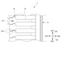
- FIG. 2 is an enlarged front view showing the front retainer of the substrate storage container according to the embodiment of the present invention.
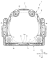
- FIG. 3 is a cross-sectional view showing the positional relationship between the substrates stored in the substrate storage container and the front retainer according to the embodiment of the present invention.
- the direction from the container body 2 to the lid 3 (direction from the upper right to the lower left in FIG. 1) will be defined as the front direction D11, and the opposite direction will be defined as the rear direction D12. are collectively defined as the front-rear direction D1.
- the direction from the lower wall 24 to the upper wall 23 (upward direction in FIG. 1), which will be described later, is defined as an upward direction D21, and the opposite direction is defined as a downward direction D22, and these are collectively referred to as the upward and downward direction D2.
- the direction from the second side wall 26 to the first side wall 25 is defined as a left direction D31, and the opposite direction is defined as a right direction D32. are collectively defined as the left-right direction D3. Arrows indicating these directions are illustrated in the main drawings.
- the substrate W (see FIG. 1) stored in the substrate storage container 1 is a disk-shaped silicon wafer, glass wafer, sapphire wafer, etc. thinned by polishing or the like, and is a thin substrate used in industry.
- the substrate W in this embodiment is a silicon wafer with a diameter of 300 mm.
- the substrate storage container 1 is used as an in-process container for storing and transporting substrates W made of silicon wafers as described above in a process within a factory, or is used as an in-process container for transporting substrates W made of silicon wafers as described above. It is used as a shipping container for transporting substrates W by transportation means such as shipping means and shipping means, and is composed of a container body 2 and a lid body 3.
- the container body 2 includes a substrate support plate-like portion 5 as a side substrate support portion and a back substrate support portion 6.
- the lid 3 includes a front retainer 7 (see FIGS. 4 to 6) having a lid-side substrate support portion 73.
- the container body 2 has a cylindrical wall portion 20 with a container body opening 21 formed at one end and closed at the other end.
- a substrate storage space 27 is formed within the container body 2.
- the substrate storage space 27 is surrounded by the wall portion 20 .
- a substrate support plate-shaped portion 5 is disposed in a portion of the wall portion 20 that forms the substrate storage space 27.
- the substrate storage space 27 can accommodate a plurality of substrates W.
- the substrate support plate-like portions 5 are provided on the wall portion 20 so as to form a pair within the substrate storage space 27.
- the substrate support plate-shaped portion 5 contacts the edges of the plurality of substrates W, thereby supporting the adjacent substrates W. It is possible to support the edges of a plurality of substrates W in a state in which they are spaced apart from each other at a predetermined interval and arranged in parallel.
- a rear substrate support section 6 is provided on the rear side of the substrate support plate-like section 5.
- the back substrate support portion 6 (see FIG. 2, etc.) is provided on the wall portion 20 in the substrate storage space 27 so as to form a pair with a front retainer 7 (see FIG. 3, etc.), which will be described later.
- the back side substrate support part 6 supports the plurality of substrates W by abutting against the edges of the plurality of substrates W when the container main body opening 21 is closed by the lid 3 (in the closed state). The rear of the edge can be supported.
- the lid 3 is attachable to and detachable from the opening peripheral portion 28 (see FIG. 1, etc.) that forms the container main body opening 21, and is capable of closing the container main body opening 21.
- the front retainer 7 is provided in a portion of the lid 3 that faces the substrate storage space 27 when the container main body opening 21 is closed by the lid 3.
- the front retainer 7 is arranged inside the board storage space 27 so as to form a pair with the back board support section 6 .
- the front retainer 7 can support the front edges of the plurality of substrates W by coming into contact with the edges of the plurality of substrates W when the container main body opening 21 is closed by the lid 3.
- the front retainer 7 supports a plurality of substrates W in cooperation with the back substrate support section 6 when the container main body opening 21 is closed by the lid 3, thereby keeping adjacent substrates W in a predetermined position. They are held in parallel and spaced apart from each other.
- the substrate storage container 1 is made of resin such as a plastic material, and examples of the resin material include polycarbonate, cycloolefin polymer, polyetherimide, polyether ketone, polybutylene terephthalate, polyether ether ketone, and liquid crystal.
- the resin material include polycarbonate, cycloolefin polymer, polyetherimide, polyether ketone, polybutylene terephthalate, polyether ether ketone, and liquid crystal.
- thermoplastic resins such as polymers and alloys thereof.
- electrically conductive substances such as carbon fibers, carbon powder, carbon nanotubes, and electrically conductive polymers are selectively added. It is also possible to add glass fiber, carbon fiber, etc. to increase rigidity.
- the wall portion 20 of the container body 2 includes a back wall 22, an upper wall 23, a lower wall 24, a first side wall 25, and a second side wall 26.
- the back wall 22, the upper wall 23, the lower wall 24, the first side wall 25, and the second side wall 26 are made of the above-mentioned materials and are integrally molded.
- the first side wall 25 and the second side wall 26 are opposed to each other, and the upper wall 23 and lower wall 24 are opposed to each other.
- the rear end of the upper wall 23 , the rear end of the lower wall 24 , the rear end of the first side wall 25 , and the rear end of the second side wall 26 are all connected to the back wall 22 .
- the front end of the upper wall 23, the front end of the lower wall 24, the front end of the first side wall 25, and the front end of the second side wall 26 have a positional relationship facing the back wall 22, and the container main body opening 21 has a substantially rectangular shape.
- An opening peripheral portion 28 is formed.
- the opening peripheral portion 28 is provided at one end of the container body 2, and the back wall 22 is located at the other end of the container body 2.
- the outer shape of the container body 2 formed by the outer surface of the wall portion 20 is box-shaped.
- the inner surface of the wall portion 20, that is, the inner surface of the back wall 22, the inner surface of the upper wall 23, the inner surface of the lower wall 24, the inner surface of the first side wall 25, and the inner surface of the second side wall 26 is a substrate storage space surrounded by these. 27 is formed.
- the container main body opening 21 formed in the opening peripheral portion 28 is surrounded by the wall portion 20 and communicates with a substrate storage space 27 formed inside the container main body 2 .
- the substrate storage space 27 can accommodate up to 13 substrates W.
- the substrate storage structure is capable of storing 13 substrates W, but by removing the substrate support plate portion 5, a substrate support plate portion (not shown) capable of storing 25 substrates W is provided. may be fixed to the container body 2 to form a structure of a substrate storage container capable of storing 25 substrates W.
- latch engagement recesses 231A and 231B recessed toward the outside of the board storage space 27 are provided in the upper wall 23 and the lower wall 24 near the opening periphery 28. , 241A, and 241B are formed. A total of four latch engagement recesses 231A, 231B, 241A, and 241B are formed, one each near the left and right ends of the upper wall 23 and the lower wall 24.
- a top flange 236 is fixed to the center of the upper wall 23.
- the top flange 236 is a member that becomes a part of the substrate storage container 1 that is hung and suspended when the substrate storage container 1 is suspended in an AMHS (automatic wafer transfer system), a PGV (wafer substrate transfer vehicle), or the like.
- the substrate support plate-like portions 5 are provided on the first side wall 25 and the second side wall 26, respectively, and are arranged in the substrate storage space 27 so as to form a pair in the left-right direction D3.
- substrate support plate-shaped part 5 may be integrally molded with the 1st side wall 25 and the 2nd side wall 26, and may be provided.
- the substrate support plate-shaped portion 5 has a plate-like substantially arc shape.
- a total of 26 substrate support plate-shaped portions 5 are provided, 13 of which are provided in the vertical direction D2 on each of the first side wall 25 side and the second side wall 26 side.
- Adjacent substrate support plate-like portions 5 are arranged parallel to each other and spaced apart from each other at intervals of 10 mm to 30 mm in the vertical direction D2.
- another plate-shaped member is arranged above the uppermost substrate support plate-shaped part 5 in parallel with the substrate support plate-shaped part 5. This is a member that serves as a guide for the uppermost board W to be inserted into the board storage space 27 during insertion.
- the 13 substrate support plate-like portions 5 disposed on the first side wall 25 and the 13 substrate support plate-like portions 5 disposed on the second side wall 26 have a positional relationship in which they face each other in the left-right direction D3.
- the thirteen substrate support plate-like portions 5 and a member serving as a plate-like guide parallel to the substrate support plate-like portion 5 have a positional relationship parallel to the inner surface of the lower wall 24 .
- a convex portion is provided on the upper surface of the substrate support plate-like portion 5.
- the substrate W supported by the substrate support plate-like part 5 contacts only the protruding end of the convex part, and does not contact the substrate support plate-like part 5 in a planar manner.
- the substrate support plate-shaped portion 5 supports the edges of the plurality of substrates W in a state in which adjacent substrates W among the plurality of substrates W are spaced apart from each other by a predetermined interval and are positioned parallel to each other. It is possible.
- the back substrate support section 6 has a back end edge support section 60.
- the rear edge support portion 60 is integrally formed with the rear end portion of the substrate support plate-like portion 5 .
- the back substrate support section 6 may be provided integrally with the first side wall 25, the second side wall 26, and the back wall 22.
- the number of rear edge support portions 60 corresponding to each substrate W that can be stored in the substrate storage space 27, specifically thirteen, is provided.
- the rear edge support portions 60 disposed on the first side wall 25 side and the second side wall 26 side have a positional relationship such that they form a pair with a front retainer 7, which will be described later, in the front-rear direction D1.
- the back edge support portion 60 supports the edge of the substrate W by sandwiching it.
- the lid 3 has a substantially rectangular shape that substantially matches the shape of the opening peripheral portion 28 of the container body 2, as shown in FIG. 1 and the like.
- the lid 3 is removable from the opening periphery 28 of the container main body 2, and by attaching the lid 3 to the opening periphery 28, the lid 3 can close the container main opening 21.
- An annular sealing member 4 is attached to the inner surface of the lid 3 (the back surface of the lid 3 shown in FIG. 1).
- the sealing member 4 is made of various thermoplastic elastomers such as elastically deformable polyester and polyolefin, fluororubber, silicone rubber, and the like.
- the seal member 4 is arranged so as to go around the outer peripheral edge of the lid body 3.
- the sealing member 4 When the lid 3 is attached to the opening periphery 28 , the sealing member 4 is sandwiched between the opening periphery 28 and the inner surface of the lid 3 and elastically deforms, and the lid 3 closes the container body opening 21 . Closed in a sealed state. By removing the lid 3 from the opening peripheral portion 28, the substrate W can be taken in and out of the substrate storage space 27 within the container body 2.
- the lid body 3 has a lid body that forms the outer shape of the lid body 3, and the lid body is provided with a latch mechanism.
- the latch mechanism is provided near both left and right ends of the lid body, and as shown in FIG. It includes two lower latch parts 32B that can protrude from the lower side in the downward direction D22.
- the two upper latch parts 32A are arranged near both left and right ends of the upper side of the lid body, and the two lower latch parts 32B are arranged near both left and right ends of the lower side of the lid body.
- An operating section 33 is provided on the outer surface of the lid body.
- the upper latch portion 32A and the lower latch portion 32B can be made to protrude from the upper and lower sides of the lid body, or can be prevented from protruding from the upper and lower sides. can do.
- the upper latch portion 32A protrudes from the upper side of the lid body in the upward direction D21 and engages with the latch engagement recesses 231A and 231B of the container body 2
- the lower latch portion 32B protrudes downward from the lower side of the lid body.
- a recess 34 is formed which is recessed toward the outside of the substrate storage space 27 (in the front direction D11).
- a front retainer 7 is fixedly provided in a portion of the lid main body inside the recess 34.
- the front retainer 7 includes a lid-side substrate support portion 73, leg portions 72, and a vertical frame body 71. Twenty-five lid-side substrate support sections 73 are provided in the vertical direction D2, and one each is supported by an elastically deformable leg section 72. The leg portion 72 extends in the right direction D32 so as to be separated from the lid body side substrate support portion 73. As shown in FIGS. 4 to 6, a vertical frame body 71 extending along the vertical direction D2 is provided at the end of the leg portion 72 and integrally formed with the leg portion 72. As shown in FIGS.
- the lid-side substrate support section 73 is located at the free end of a cantilever spring that configures the leg section 72 as a cantilever beam.
- the lid side substrate support section 73 uses the elastic force of the legs 72 to move the frontmost edge of the edge of the substrate W into the substrate storage space. It is held and supported while being biased towards the center of the space 27.
- the rear surface of the lid-side substrate support section 73 has a support flat surface 731 that supports the substrate W by coming into contact with the substrate W at one point on the peripheral surface of the edge of each of the plurality of substrates W.
- a plurality of support flat surfaces 731 are provided in one-to-one correspondence on the circumferential surfaces of the respective edges of the plurality of substrates W, and are constituted by vertical planes.
- the support flat surface 731 comes into contact with the edge of the front surface (upper surface) of the substrate W when the container main body opening 21 is closed by the lid 3 .
- the lid body side substrate support part 73 is elastically displaceable in a direction from the other end of the container body 2 to one end (forward direction D11) when the container body opening 21 is closed by the lid 3. It is.
- the lid side substrate support section 73 has a rectangular half connected to the leg section 72 at a center position in the left-right direction D3, and a rectangular half on the tip side. It has a shape that is shifted downward D22. Therefore, the lower end portion on the left side of the support flat surface 731 of one lid-side substrate support portion 73 and the upper end portion on the right side of the support flat surface 731 of the lid-side substrate support portion 73 one below. constitute overlapping portions 733 that face each other in the left-right direction D3, which is a direction parallel to the upper surface of the substrate W, as shown in FIG.
- the length H1 of the free end edge of the support flat surface 731 of the lid-side substrate support portion 73 in the parallel direction of the plurality of substrates W stored in the substrate storage space 27, that is, the vertical direction D2, is 5 mm or more and 9 mm. It is as follows.
- the area S1 of the support flat surface 731 is 50 mm 2 or more and 71.5 mm 2 or less.
- the length H1 of the free end side edge of the support flat surface 731 of the lid side substrate support part 73 in the vertical direction D2 is 5 mm or more, the area S1 in contact with the circumferential surface of the edge of the substrate W is 50 mm 2 Even if the thin substrate W is bent, it is difficult to apply force to the substrate W itself, and it is possible to make the substrate W difficult to break. As a result, it is possible to make the substrate W less likely to be damaged. Furthermore, the length H1 of the free end side edge of the support flat surface 731 of the lid side substrate support part 73 in the vertical direction D2 is more preferably 7 mm or more, which further makes the substrate W less likely to break. becomes possible.
- the length H1 of the free end side edge of the support flat surface 731 of the lid body side substrate support part 73 in the vertical direction D2 is 9 mm or less, the area in contact with the circumferential surface of the edge of the substrate W is 71 mm or less. .5 mm 2 so that the number of boards W that can be stored in the substrate storage container 1 is not less than the number of boards that can be stored in a normal substrate storage container. It is more preferable that the length H1 of the free end side edge of the support flat surface 731 of the lid side substrate support part 73 in the vertical direction D2 is 8.4 mm or less. It is possible to prevent the number of sheets from becoming less than the number of sheets stored.
- the lid side substrate support part 73 has a support flat surface 731 that supports the substrate W by contacting the peripheral surface of the edge of each of the plurality of substrates W, and supports each of the adjacent substrates W among the plurality of substrates W.
- the supporting flat surface 731 that comes into contact with the circumferential surface of the edge of the substrate W has an overlapping portion 733 that faces in a direction parallel to the upper surface of the substrate W.
- a plurality of supporting flat surfaces 731 are provided on the circumferential surface of each edge of the plurality of substrates W in one-to-one correspondence. With this configuration, one support flat surface 731 comes into contact with the peripheral surface of the edge of one substrate W, so that one substrate W can be supported by one support flat surface 731.
- the support flat surface 731 is located at the free end of the cantilever spring. This configuration allows support flat surface 731 to be supported by a cantilever spring. As a result, the substrate W can be supported by the support flat surface 731 with an appropriate biasing force.
- the length H1 of the support flat surface 731 in the parallel direction of the plurality of substrates W is 5 mm or more.
- the area of the edge of the substrate W that comes into contact with the peripheral surface can be increased to 50 mm 2 or more. Therefore, since it is possible to support the substrate W on the support flat surface 731 with a wide area, even if the thin substrate W is bent, force is hardly applied to the substrate W itself, making the substrate W difficult to break. Is possible. As a result, it is possible to make the substrate W less likely to be damaged.
- the configurations of the side substrate support portion (substrate support plate-like portion 5), the lid side substrate support portion 73, and the back substrate support portion 6 are not limited to the configurations of the embodiment.
- the substrate W in this embodiment was a silicon wafer with a diameter of 300 mm, it is not limited to this value.
- Substrate storage container 1 Substrate storage container 2 Container body 3 Lid body 5 Substrate support plate-shaped part (side substrate support part) 6 Back side substrate support part 20 Wall part 21 Container main body opening 27 Substrate storage space 28 Opening peripheral part 73 Lid side substrate support part 731 Support flat surface 733 Overlap part H1 Length W Substrate
Landscapes
- Packaging Frangible Articles (AREA)
- Container, Conveyance, Adherence, Positioning, Of Wafer (AREA)
Priority Applications (6)
| Application Number | Priority Date | Filing Date | Title |
|---|---|---|---|
| US18/870,597 US20260026299A1 (en) | 2022-05-31 | 2022-05-31 | Substrate storing container and lid-body-side substrate support part |
| PCT/JP2022/022223 WO2023233554A1 (ja) | 2022-05-31 | 2022-05-31 | 基板収納容器及び蓋体側基板支持部 |
| JP2024524051A JPWO2023233554A1 (https=) | 2022-05-31 | 2022-05-31 | |
| CN202280096482.8A CN119343766A (zh) | 2022-05-31 | 2022-05-31 | 基板收纳容器以及盖体侧基板支承部 |
| KR1020247037674A KR20250019627A (ko) | 2022-05-31 | 2022-05-31 | 기판수납용기 및 뚜껑측 기판지지부 |
| TW112119628A TW202348529A (zh) | 2022-05-31 | 2023-05-26 | 基板收納容器以及蓋體側基板支承部 |
Applications Claiming Priority (1)
| Application Number | Priority Date | Filing Date | Title |
|---|---|---|---|
| PCT/JP2022/022223 WO2023233554A1 (ja) | 2022-05-31 | 2022-05-31 | 基板収納容器及び蓋体側基板支持部 |
Publications (1)
| Publication Number | Publication Date |
|---|---|
| WO2023233554A1 true WO2023233554A1 (ja) | 2023-12-07 |
Family
ID=89025941
Family Applications (1)
| Application Number | Title | Priority Date | Filing Date |
|---|---|---|---|
| PCT/JP2022/022223 Ceased WO2023233554A1 (ja) | 2022-05-31 | 2022-05-31 | 基板収納容器及び蓋体側基板支持部 |
Country Status (6)
| Country | Link |
|---|---|
| US (1) | US20260026299A1 (https=) |
| JP (1) | JPWO2023233554A1 (https=) |
| KR (1) | KR20250019627A (https=) |
| CN (1) | CN119343766A (https=) |
| TW (1) | TW202348529A (https=) |
| WO (1) | WO2023233554A1 (https=) |
Citations (6)
| Publication number | Priority date | Publication date | Assignee | Title |
|---|---|---|---|---|
| JPH01129836U (https=) * | 1988-02-25 | 1989-09-04 | ||
| JPH07307379A (ja) * | 1994-05-12 | 1995-11-21 | Kakizaki Seisakusho:Kk | 薄板用支持容器 |
| JP2005508814A (ja) * | 2001-11-14 | 2005-04-07 | エンテグリス・インコーポレーテッド | ウエハ保持システムを備えたウエハ・キャリア |
| JP2007153414A (ja) * | 2005-12-07 | 2007-06-21 | Shin Etsu Polymer Co Ltd | リテーナ及び基板収納容器 |
| JP2016018961A (ja) * | 2014-07-10 | 2016-02-01 | ミライアル株式会社 | 基板収納容器及びリテーナ |
| WO2018185894A1 (ja) * | 2017-04-05 | 2018-10-11 | ミライアル株式会社 | 基板収納容器 |
Family Cites Families (23)
| Publication number | Priority date | Publication date | Assignee | Title |
|---|---|---|---|---|
| JPH069850Y2 (ja) * | 1987-06-15 | 1994-03-16 | 日本板硝子株式会社 | 車両用窓ガラス |
| JP3145252B2 (ja) * | 1994-07-29 | 2001-03-12 | 淀川化成株式会社 | 基板支承用側板およびそれを用いたカセット |
| JP3180693B2 (ja) * | 1996-11-21 | 2001-06-25 | 三菱マテリアル株式会社 | ウェーハ収納容器のウェーハ押え部材 |
| JPH11121601A (ja) * | 1997-10-20 | 1999-04-30 | Dainippon Ink & Chem Inc | ウエハ収納容器 |
| JP3938293B2 (ja) * | 2001-05-30 | 2007-06-27 | 信越ポリマー株式会社 | 精密基板収納容器及びその押さえ部材 |
| KR100615761B1 (ko) * | 2002-09-11 | 2006-08-28 | 신에츠 폴리머 가부시키가이샤 | 기판 수납 용기 |
| JP4667769B2 (ja) * | 2004-06-11 | 2011-04-13 | 信越ポリマー株式会社 | 基板収納容器 |
| US7523830B2 (en) * | 2004-11-23 | 2009-04-28 | Entegris, Inc. | Wafer container with secondary wafer restraint system |
| JP2006269771A (ja) * | 2005-03-24 | 2006-10-05 | Miraial Kk | 気密容器 |
| US8528738B2 (en) * | 2006-06-13 | 2013-09-10 | Entegris, Inc. | Reusable resilient cushion for wafer container |
| JP5270668B2 (ja) * | 2008-04-25 | 2013-08-21 | 信越ポリマー株式会社 | リテーナ、及びリテーナを備えた基板収納容器 |
| TWI384577B (zh) * | 2008-07-31 | 2013-02-01 | 家登精密工業股份有限公司 | 門上凹陷區域兩旁配置有晶圓限制件模組之前開式晶圓盒 |
| TWD176128S (zh) * | 2010-03-11 | 2016-06-01 | 安堤格里斯公司 | 用於晶圓載運器之襯墊 |
| JP6114193B2 (ja) * | 2010-10-20 | 2017-04-12 | インテグリス・インコーポレーテッド | ドア・ガイドおよびシールを備えたウェーハ容器 |
| KR20150066540A (ko) * | 2012-10-12 | 2015-06-16 | 미라이얼 가부시키가이샤 | 기판 수납 용기 |
| KR102062672B1 (ko) * | 2012-11-20 | 2020-01-06 | 미라이얼 가부시키가이샤 | 기판 수납 용기 |
| KR20140092548A (ko) * | 2013-01-16 | 2014-07-24 | 삼성전자주식회사 | 웨이퍼 보관 장치 |
| US9887116B2 (en) * | 2014-03-26 | 2018-02-06 | Miraial Co., Ltd. | Substrate storing container |
| SG11201707411QA (en) * | 2015-04-10 | 2017-10-30 | Shinetsu Polymer Co | Substrate storage container |
| KR102363033B1 (ko) * | 2015-07-03 | 2022-02-15 | 미라이얼 가부시키가이샤 | 기판 수납 용기 |
| JP7445741B2 (ja) * | 2019-07-19 | 2024-03-07 | インテグリス・インコーポレーテッド | ウェハクッション、ウェハキャリアおよびウェハを支持する方法 |
| JP7414982B2 (ja) * | 2020-05-19 | 2024-01-16 | ミライアル株式会社 | 基板収納容器 |
| TWI855914B (zh) * | 2023-05-04 | 2024-09-11 | 家登精密工業股份有限公司 | 基板容器保護裝置 |
-
2022
- 2022-05-31 KR KR1020247037674A patent/KR20250019627A/ko active Pending
- 2022-05-31 US US18/870,597 patent/US20260026299A1/en active Pending
- 2022-05-31 WO PCT/JP2022/022223 patent/WO2023233554A1/ja not_active Ceased
- 2022-05-31 CN CN202280096482.8A patent/CN119343766A/zh active Pending
- 2022-05-31 JP JP2024524051A patent/JPWO2023233554A1/ja active Pending
-
2023
- 2023-05-26 TW TW112119628A patent/TW202348529A/zh unknown
Patent Citations (6)
| Publication number | Priority date | Publication date | Assignee | Title |
|---|---|---|---|---|
| JPH01129836U (https=) * | 1988-02-25 | 1989-09-04 | ||
| JPH07307379A (ja) * | 1994-05-12 | 1995-11-21 | Kakizaki Seisakusho:Kk | 薄板用支持容器 |
| JP2005508814A (ja) * | 2001-11-14 | 2005-04-07 | エンテグリス・インコーポレーテッド | ウエハ保持システムを備えたウエハ・キャリア |
| JP2007153414A (ja) * | 2005-12-07 | 2007-06-21 | Shin Etsu Polymer Co Ltd | リテーナ及び基板収納容器 |
| JP2016018961A (ja) * | 2014-07-10 | 2016-02-01 | ミライアル株式会社 | 基板収納容器及びリテーナ |
| WO2018185894A1 (ja) * | 2017-04-05 | 2018-10-11 | ミライアル株式会社 | 基板収納容器 |
Also Published As
| Publication number | Publication date |
|---|---|
| US20260026299A1 (en) | 2026-01-22 |
| KR20250019627A (ko) | 2025-02-10 |
| JPWO2023233554A1 (https=) | 2023-12-07 |
| TW202348529A (zh) | 2023-12-16 |
| CN119343766A (zh) | 2025-01-21 |
Similar Documents
| Publication | Publication Date | Title |
|---|---|---|
| JP7414982B2 (ja) | 基板収納容器 | |
| CN110574152B (zh) | 基板收纳容器 | |
| JP6177248B2 (ja) | 基板収納容器 | |
| KR102677319B1 (ko) | 기판 수납 용기 | |
| JP6106271B2 (ja) | 基板収納容器 | |
| JP7562657B2 (ja) | 基板収納容器 | |
| CN106796904A (zh) | 基板收纳容器 | |
| JP6067129B2 (ja) | 基板収納容器 | |
| JP2016149492A (ja) | 基板収納容器 | |
| JP2016048757A (ja) | 基板収納容器 | |
| WO2023248464A1 (ja) | 基板収納容器及びリアリテーナ | |
| WO2023233554A1 (ja) | 基板収納容器及び蓋体側基板支持部 | |
| TW202032700A (zh) | 基板收納容器 | |
| KR102930874B1 (ko) | 기판수납용기, 그 제조방법 및 뚜껑체측 기판지지부 | |
| TWI652211B (zh) | Substrate storage container and holding member | |
| JP2017147365A (ja) | 基板収納容器 | |
| TWI781205B (zh) | 基板收納容器 | |
| KR102942671B1 (ko) | 기판수납용기 및 그 뚜껑 | |
| WO2025074498A1 (ja) | 基板収納容器 | |
| WO2026047841A1 (ja) | 基板収納容器 | |
| WO2024105879A1 (ja) | 収納容器及びアダプター部材 | |
| WO2025109707A1 (ja) | 基板収納容器 | |
| JP2016058629A (ja) | 基板収納容器 |
Legal Events
| Date | Code | Title | Description |
|---|---|---|---|
| 121 | Ep: the epo has been informed by wipo that ep was designated in this application |
Ref document number: 22944841 Country of ref document: EP Kind code of ref document: A1 |
|
| DPE1 | Request for preliminary examination filed after expiration of 19th month from priority date (pct application filed from 20040101) | ||
| WWE | Wipo information: entry into national phase |
Ref document number: 202280096482.8 Country of ref document: CN |
|
| WWE | Wipo information: entry into national phase |
Ref document number: 2024524051 Country of ref document: JP |
|
| WWE | Wipo information: entry into national phase |
Ref document number: 18870597 Country of ref document: US |
|
| NENP | Non-entry into the national phase |
Ref country code: DE |
|
| WWP | Wipo information: published in national office |
Ref document number: 202280096482.8 Country of ref document: CN |
|
| WWP | Wipo information: published in national office |
Ref document number: 1020247037674 Country of ref document: KR |
|
| 122 | Ep: pct application non-entry in european phase |
Ref document number: 22944841 Country of ref document: EP Kind code of ref document: A1 |
|
| WWP | Wipo information: published in national office |
Ref document number: 18870597 Country of ref document: US |