WO2023188649A1 - 電動作業機械 - Google Patents
電動作業機械 Download PDFInfo
- Publication number
- WO2023188649A1 WO2023188649A1 PCT/JP2022/047996 JP2022047996W WO2023188649A1 WO 2023188649 A1 WO2023188649 A1 WO 2023188649A1 JP 2022047996 W JP2022047996 W JP 2022047996W WO 2023188649 A1 WO2023188649 A1 WO 2023188649A1
- Authority
- WO
- WIPO (PCT)
- Prior art keywords
- power supply
- power
- inverter
- control
- supply system
- Prior art date
- Legal status (The legal status is an assumption and is not a legal conclusion. Google has not performed a legal analysis and makes no representation as to the accuracy of the status listed.)
- Ceased
Links
Images

Classifications
-
- E—FIXED CONSTRUCTIONS
- E02—HYDRAULIC ENGINEERING; FOUNDATIONS; SOIL SHIFTING
- E02F—DREDGING; SOIL-SHIFTING
- E02F9/00—Component parts of dredgers or soil-shifting machines, not restricted to one of the kinds covered by groups E02F3/00 - E02F7/00
- E02F9/24—Safety devices, e.g. for preventing overload
-
- B—PERFORMING OPERATIONS; TRANSPORTING
- B60—VEHICLES IN GENERAL
- B60L—PROPULSION OF ELECTRICALLY-PROPELLED VEHICLES; SUPPLYING ELECTRIC POWER FOR AUXILIARY EQUIPMENT OF ELECTRICALLY-PROPELLED VEHICLES; ELECTRODYNAMIC BRAKE SYSTEMS FOR VEHICLES IN GENERAL; MAGNETIC SUSPENSION OR LEVITATION FOR VEHICLES; MONITORING OPERATING VARIABLES OF ELECTRICALLY-PROPELLED VEHICLES; ELECTRIC SAFETY DEVICES FOR ELECTRICALLY-PROPELLED VEHICLES
- B60L50/00—Electric propulsion with power supplied within the vehicle
- B60L50/50—Electric propulsion with power supplied within the vehicle using propulsion power supplied by batteries or fuel cells
- B60L50/60—Electric propulsion with power supplied within the vehicle using propulsion power supplied by batteries or fuel cells using power supplied by batteries
-
- E—FIXED CONSTRUCTIONS
- E02—HYDRAULIC ENGINEERING; FOUNDATIONS; SOIL SHIFTING
- E02F—DREDGING; SOIL-SHIFTING
- E02F3/00—Dredgers; Soil-shifting machines
- E02F3/04—Dredgers; Soil-shifting machines mechanically-driven
- E02F3/28—Dredgers; Soil-shifting machines mechanically-driven with digging tools mounted on a dipper- or bucket-arm, i.e. there is either one arm or a pair of arms, e.g. dippers, buckets
- E02F3/30—Dredgers; Soil-shifting machines mechanically-driven with digging tools mounted on a dipper- or bucket-arm, i.e. there is either one arm or a pair of arms, e.g. dippers, buckets with a dipper-arm pivoted on a cantilever beam, i.e. boom
- E02F3/32—Dredgers; Soil-shifting machines mechanically-driven with digging tools mounted on a dipper- or bucket-arm, i.e. there is either one arm or a pair of arms, e.g. dippers, buckets with a dipper-arm pivoted on a cantilever beam, i.e. boom working downwardly and towards the machine, e.g. with backhoes
- E02F3/325—Backhoes of the miniature type
-
- E—FIXED CONSTRUCTIONS
- E02—HYDRAULIC ENGINEERING; FOUNDATIONS; SOIL SHIFTING
- E02F—DREDGING; SOIL-SHIFTING
- E02F9/00—Component parts of dredgers or soil-shifting machines, not restricted to one of the kinds covered by groups E02F3/00 - E02F7/00
- E02F9/08—Superstructures; Supports for superstructures
- E02F9/0858—Arrangement of component parts installed on superstructures not otherwise provided for, e.g. electric components, fenders, air-conditioning units
- E02F9/0866—Engine compartment, e.g. heat exchangers, exhaust filters, cooling devices, silencers, mufflers, position of hydraulic pumps in the engine compartment
-
- E—FIXED CONSTRUCTIONS
- E02—HYDRAULIC ENGINEERING; FOUNDATIONS; SOIL SHIFTING
- E02F—DREDGING; SOIL-SHIFTING
- E02F9/00—Component parts of dredgers or soil-shifting machines, not restricted to one of the kinds covered by groups E02F3/00 - E02F7/00
- E02F9/16—Cabins, platforms, or the like, for drivers
- E02F9/166—Cabins, platforms, or the like, for drivers movable, tiltable or pivoting, e.g. movable seats, dampening arrangements of cabins
-
- E—FIXED CONSTRUCTIONS
- E02—HYDRAULIC ENGINEERING; FOUNDATIONS; SOIL SHIFTING
- E02F—DREDGING; SOIL-SHIFTING
- E02F9/00—Component parts of dredgers or soil-shifting machines, not restricted to one of the kinds covered by groups E02F3/00 - E02F7/00
- E02F9/20—Drives; Control devices
- E02F9/2058—Electric or electro-mechanical or mechanical control devices of vehicle sub-units
- E02F9/2062—Control of propulsion units
- E02F9/207—Control of propulsion units of the type electric propulsion units, e.g. electric motors or generators
-
- E—FIXED CONSTRUCTIONS
- E02—HYDRAULIC ENGINEERING; FOUNDATIONS; SOIL SHIFTING
- E02F—DREDGING; SOIL-SHIFTING
- E02F9/00—Component parts of dredgers or soil-shifting machines, not restricted to one of the kinds covered by groups E02F3/00 - E02F7/00
- E02F9/20—Drives; Control devices
- E02F9/2058—Electric or electro-mechanical or mechanical control devices of vehicle sub-units
- E02F9/2091—Control of energy storage means for electrical energy, e.g. battery or capacitors
-
- E—FIXED CONSTRUCTIONS
- E02—HYDRAULIC ENGINEERING; FOUNDATIONS; SOIL SHIFTING
- E02F—DREDGING; SOIL-SHIFTING
- E02F9/00—Component parts of dredgers or soil-shifting machines, not restricted to one of the kinds covered by groups E02F3/00 - E02F7/00
- E02F9/20—Drives; Control devices
- E02F9/2058—Electric or electro-mechanical or mechanical control devices of vehicle sub-units
- E02F9/2095—Control of electric, electro-mechanical or mechanical equipment not otherwise provided for, e.g. ventilators, electro-driven fans
-
- B—PERFORMING OPERATIONS; TRANSPORTING
- B60—VEHICLES IN GENERAL
- B60L—PROPULSION OF ELECTRICALLY-PROPELLED VEHICLES; SUPPLYING ELECTRIC POWER FOR AUXILIARY EQUIPMENT OF ELECTRICALLY-PROPELLED VEHICLES; ELECTRODYNAMIC BRAKE SYSTEMS FOR VEHICLES IN GENERAL; MAGNETIC SUSPENSION OR LEVITATION FOR VEHICLES; MONITORING OPERATING VARIABLES OF ELECTRICALLY-PROPELLED VEHICLES; ELECTRIC SAFETY DEVICES FOR ELECTRICALLY-PROPELLED VEHICLES
- B60L2200/00—Type of vehicles
- B60L2200/40—Working vehicles
Definitions
- the present invention relates to electric working machines such as hydraulic excavators.
- Construction machines such as hydraulic excavators are configured so that the cab can be tilted up relative to the revolving frame, making it easier to maintain parts such as hydraulic equipment and wiring located below the cab.
- parts such as hydraulic equipment and wiring located below the cab.
- Patent Document 1 One is known that has a function of prohibiting the operation of an engine or a hydraulic actuator when it is detected that the driver's cab is tilted up.
- An object of the present invention is to provide an electric working machine that can sufficiently reduce the voltage of the electrical system during maintenance.
- the present invention includes an electric motor as a prime mover, an inverter that controls the electric motor, a power supply system that supplies power to the inverter, and a system that stores the power supplied from the power supply system.
- Electric work comprising: a drive battery device that supplies the inverter; a control battery that supplies control power to the inverter, the power supply system, and the drive battery device; and an opening/closing cover that covers the power supply system.
- the present invention provides an electric working machine including a control power cutoff device that cuts off the supply of control power to the inverter, the power supply system, and the drive battery device in conjunction with opening of the opening/closing cover.
- the voltage of the electrical system can be sufficiently lowered during maintenance of an electric working machine.
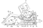
- a side view of an electric working machine according to an embodiment of the present invention Diagram showing the state in which the cab of the electric working machine in Figure 1 is tilted.
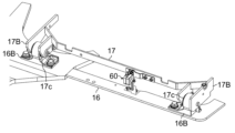
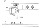
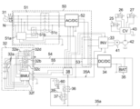
- Configuration diagram of a sensor that detects the tilt-up state of the cab installed in the electric working machine shown in Figure 1 Circuit diagram of the main parts of the electric system of the electric working machine shown in Figure 1
- FIG. 1 is a side view of an electric working machine according to an embodiment of the present invention
- FIG. 2 is a diagram showing a state in which the driver's cab of the electric working machine shown in FIG. 1 is tilted.
- the direction in which the operator sitting in the driver's seat faces (the left direction in FIG. 1) will be defined as the front of the revolving structure 12.
- a hydraulic excavator will be described as an example of an electric working machine, but the present invention is also applicable to other electric working machines such as a wheel loader and a bulldozer.
- the electric working machine shown in FIG. 1 is a hydraulic excavator, and includes a vehicle body 10 and a front working machine 20 connected to the vehicle body 10.
- the vehicle body 10 includes a running body 11 and a rotating body 12.
- the traveling body 11 forms the base structure of the electric working machine, and is a crawler-type traveling body provided with left and right crawler tracks 13.
- the left and right crawler belts 13 are driven by left and right travel drive devices 14, respectively.
- the travel drive device 14 includes a travel motor (hydraulic motor) and a reduction gear.
- a blade (earth removal device) 11a is attached to the front part of the frame (truck frame) of the traveling body 11. The blade 11a is moved up and down by a blade cylinder (not shown).
- a revolving body 12 is provided above the traveling body 11 via a turning wheel 15, and by driving the rotating wheel 15 with a turning motor (not shown), the rotating body 12 is vertically aligned with respect to the traveling body 11. Rotate around an axis.
- the swing motor is a hydraulic motor, but if an electric motor is used, the hydraulic motor and the electric motor may be used together.
- a crawler-type traveling body 11 is illustrated, but the traveling body 11 may be a wheel-type traveling body 11.
- the revolving body 12 includes a revolving frame 16, a cab (driver's cab) 17, an exterior cover 18, a counterweight 19, and the like.
- the revolving frame 16 is a base frame of the revolving body 12. This swing frame 16 is connected to the traveling body 11 via a swing wheel 15. A swing post 16a is connected to the front portion of the swing frame 16 via a vertically extending shaft (not shown). The swing post 16a swings left and right by a swing cylinder (not shown).
- the driver's cab 17 is mounted on the revolving frame 16.
- the driver's cab 17 includes a driver's seat 17a where an operator sits, a control lever device 17b which is operated by the operator, and the like.
- the operating lever devices 17b are, for example, electric lever devices, and are provided on the left and right sides of the driver's seat 17a. For example, tilting the lever of the right operating lever device 17b forward will lower the boom, tilting it backwards will raise the boom, tilting it to the left will instruct bucket crowding, and tilting it to the right will instruct bucket dumping.
- the driver's cab 17 is also equipped with a controller 38, a key switch 39, and the like.
- the exterior cover 18 is interposed between the rotating frame 16 and the driver's cab 17, and surrounds devices such as a power supply system 50 (FIG. 5), a power source 31, an electric motor 41 (prime mover), a hydraulic pump 42, and a control valve 43.
- a machine room is configured to accommodate these power supply systems 50 and the like.
- the machine room surrounded by the exterior cover 18 includes a drive battery device 32, an inverter 33, a DC/DC converter 34, a control battery 35, a control power cutoff device (controller relay) 36, and a key switch relay 37. is accommodated.
- the power supply system 50 includes an AC box 51, a power converter 52, a junction box 53, power transmission lines 54 and 55 (FIG. 5), and the like.
- the counterweight 19 is a weight that balances the weight with the front working machine 20, and is supported at the rear end of the swing frame 16.
- the front working machine 20 is a multi-jointed working device, and includes a working arm 21 and a bucket 22.
- the working arm 21 includes a boom 23, an arm 24, a boom cylinder 25, an arm cylinder 26, and a bucket cylinder 27.
- the boom cylinder 25, the arm cylinder 26, and the bucket cylinder 27 are all double-acting hydraulic cylinders and drive the front working machine 20.
- the boom cylinder 25 is arranged on the ventral side of the boom 23, the arm cylinder 26 on the back side of the boom 23, and the bucket cylinder 27 on the back side of the arm 24.
- the ventral side is the lower side of the working arm 21 in a posture with the tip of the arm 24 facing forward, and the dorsal side is the upper side of the working arm 21 in the same posture.
- the boom 23 is connected to the vehicle body 10 (swing post 16a) via a pin so that it can rotate up and down.
- the arm 24 is connected to the tip of the boom 23 via a pin so as to be rotatable back and forth.
- the bucket 22 is rotatably connected to the tip of the arm 24 via a pin.
- the bucket 22 is an attachment and can be replaced with another attachment such as a grapple.
- the boom cylinder 25 has a base end connected to the vehicle body 10 (swing post 16a), and a tip end connected to the boom 23.
- the arm cylinder 26 has a base end connected to the boom 23 and a distal end connected to the arm 24.
- the bucket cylinder 27 has a base end connected to the arm 24, and a distal end connected to the bucket 22 via a bucket link 22a.
- FIG. 3 is a diagram showing the main parts of the tilt mechanism provided in the electric working machine of FIG. 1, and FIG. 4 is a configuration diagram of a sensor that detects the tilt-up state of the driver's cab.
- the driver's cab 17 is connected to the rotating frame 16 via a rotating shaft 17c that extends in the horizontal direction (in the present embodiment, in the left-right direction). It is configured so that it can be tilted.
- the rotating shaft 17c is coaxially provided at two places on the left and right of the front part of the base frame of the driver's cab 17, and connects the brackets 16B and 17B provided on the rotating frame 16 and the driver's cab 17, respectively. ing.
- the rear part of the driver's cab 17 moves up and down using these rotating shafts 17c as fulcrums.
- FIG. 2 shown above shows a state in which the driver's cab 17 is tilted up.
- the upper opening of the machine room defined by the exterior cover 18 is opened and closed.
- the machine room accommodates various equipment such as the power supply system 50, and the driver's cab 17 is seated on the exterior cover 18 to close the upper opening of the machine room and cover the upper opening of the machine room.
- This also serves as an opening/closing cover that covers each device such as the power supply system 50 housed in the machine room.
- the junction box 53, inverter 33, etc. which are generally expected to have many maintenance opportunities, are placed in the rear area of the machine room (that is, the area that opens widely in the upper and lower directions opposite to the rotating shaft 17c). ( Figure 2).
- the positional relationship between maintenance target equipment such as the junction box 53 and inverter 33 and the rotating shaft 17c is set so that the operator can easily access equipment that requires frequent maintenance when the cab 17 is tilted up. There is.
- the electric working machine of this embodiment is equipped with a sensor 60 that detects the opening of the opening/closing cover that covers the power supply system 50 and the like, that is, the tilt-up state of the driver's cab 17.
- the sensor 60 is mounted on the rotating frame 16 or the driver's cab 17 (main body) so as to be located near the rotating shaft 17c (a position closer to the rotating shaft 17c than the driver's seat 17a) when viewed in the axial direction of the rotating shaft 17c of the driver's cab 17. In the embodiment, it is attached to the driver's cab 17).
- the sensor 60 may be of any type as long as it can detect a change in the distance between the two members, and may be of a contact type or a non-contact type. In this embodiment, a configuration in which a type of limit switch is used as the sensor 60 is illustrated.
- the sensor 60 includes a body 61 and a lever 62.
- the body 61 accommodates contacts (for example, microswitches) and is fixed to the frame of the driver's cab 17 via a bracket 63.
- the lever 62 is rotatably attached to the body 61 and is configured to rotate relative to the body 61 to open and close contacts inside the body 61.
- the center of rotation of the lever 62 coincides (or almost coincides) with the center line of the rotating shaft 17c of the driver's cab 17.
- a bracket 64 is attached to the swing frame 16 so as to face the rear side of the lever 62 of the sensor 60.
- the lever 62 of the sensor 60 is pressed against the bracket 64 by a spring (not shown) housed inside the body 61.
- the lever 62 engages with the bracket 64 and rotates relative to the body 61 of the sensor 60 .
- the contacts of the sensor 60 are closed in the state shown in FIG. 4 (the driver's cab 17 is in a horizontal state), but when the driver's cab 17 is tilted up (standing up from a horizontal position), the lever 62 rotates and opens.
- the contact point of the sensor 60 closes.
- FIG. 5 is a circuit diagram of the main parts of the electric system of the electric working machine of this embodiment.
- the electric system includes an inverter 33, a drive battery device 32, a power supply system 50, a controller 38, a control battery 35, a control power cutoff device 36, and the like.
- the electric motor 41 is a prime mover of a hydraulic system that drives hydraulic actuators such as the boom cylinder 25 and drives a hydraulic pump 42 .
- Pressure oil discharged from the hydraulic pump 42 is supplied to the hydraulic actuator via the control valve 43 to drive the hydraulic actuator.
- Hydraulic actuators driven by the pressure oil discharged by the hydraulic pump 42 include a boom cylinder 25, an arm cylinder 26, a bucket cylinder 27, and although not shown, a swing motor, a swing cylinder, a travel motor, and a blade cylinder. It will be done.
- the drive battery device 32 is connected to the power supply system 50, the inverter 33, and the control battery 35 via power transmission lines 54 and 55, and stores power supplied from the power supply system 50 and transfers the stored power to the inverter 33. It is also supplied to the control battery 35.
- the driving battery device 32 includes a plurality of battery modules 32a, battery relays 32b and 32c, a precharge relay 32d, a precharge resistor 32e, a BMU 32f, and the like.
- the positive terminal and negative terminal of the battery module 32a are connected to power transmission lines 54 and 55 via battery relays 32b and 32c, respectively.
- the positive terminal of the battery module 32a and the power transmission line 54 are disconnected and connected by opening and closing the contacts of the battery relay 32b.
- the negative terminal of the battery module 32a and the power transmission line 55 are disconnected and connected by opening and closing the contacts of the battery relay 32c.
- Precharge relay 32d and precharge resistor 32e serve to prevent excessive current from flowing through power transmission lines 54 and 55 when the contacts of battery relays 32b and 32c are closed.
- Precharge relay 32d and battery relays 32b and 32c are opened and closed by control signals from BMU 32f.
- BMU 32f transmits monitoring data such as the voltage and temperature of each battery module 32a to controller 38, and outputs control signals to precharge relay 32d and battery relays 32b and 32c in accordance with commands based on the monitoring data received from controller 38.
- the power supply system 50 supplies power supplied from the power source 31 to the inverter 33, the drive battery device 32, and the control battery 35 via power transmission lines 54 and 55.
- a configuration in which a vehicle-mounted three-phase AC power source is used as the power source 31 is exemplified. Electric power supplied to the drive battery device 32 and the control battery 35 is stored in the drive battery device 32 and the control battery 35, respectively.
- the power supplied to inverter 33 drives the inverter.
- the power supply system 50 includes the AC box 51, the power converter 52, the junction box 53, the power transmission lines 54 and 55, and the like.
- the AC box 51 is provided on a path that leads the three phases (L1, L2, L3 phases) of the power supply 31 and the neutral line N to the power conversion device 52.
- power from a power source 31 supplied via an AC box 51 is converted from AC (alternating current) to DC (direct current) by a power conversion device 52 and output via a junction box 53 .
- the AC box 51 is equipped with a voltage monitoring device 51a, a voltage monitoring relay 51b, and a power relay 51c.
- the voltage monitoring device 51a monitors each voltage between the L1, L2, and L3 phases and the neutral line N.
- the power monitoring device 51a operates using power from the control battery 35 supplied via the control power cutoff device 36 as a power source.
- the contacts of the voltage monitoring relay 51b close when power is being supplied to the voltage monitoring device 51a and the output of the voltage monitoring device 51a is normal. When power is not supplied to the voltage monitoring device 51a, or when the output of the voltage monitoring device 51a is abnormal, the contacts of the power monitoring relay 51b are opened.
- the power relay 51c has three contacts provided in each of the power supply paths of the L1, L2, and L3 phases that supply power from the power source 31 to the power conversion device 52, and opens and closes the three contacts to connect the power source 31 and the power.
- the power supply path connecting to the conversion device 52 is cut off and connected.
- the coil of the power supply relay 51c is connected in series to any one of the L1, L2, and L3 phases (the L1 phase in this embodiment) of the power supply 31 via the contact of the voltage monitoring relay 51b.
- the contacts of the power supply monitoring relay 51b are closed (when the voltage monitoring device 51a is energized and the output of the voltage monitoring device 51a is normal), the contacts of the power supply relay 51c are closed, and the power is transferred from the AC box 51 to the power conversion device 52. Power is supplied to the When the contact of the power supply monitoring relay 51b is open (when the voltage monitoring device 51a is not energized or the output of the voltage monitoring device 51a is abnormal), the contact of the power supply relay 51c is opened and the power from the AC box 51 is Power supply to the power conversion device 52 is cut off.
- the power conversion device 52 converts the power supplied from the power supply 31 via the AC box 51 from AC (alternating current) to DC (direct current) and outputs it to the power transmission lines 54 and 55.
- the power output from the power conversion device 52 to the power transmission lines 54 and 55 is distributed via the junction box 53 and supplied to the inverter 33, the driving battery device 32, and the control battery 35. Electric power supplied to the drive battery device 32 and the control battery 35 is stored in the drive battery device 32 and the control battery 35, respectively.
- the power supplied to inverter 33 drives the inverter.
- the control battery 35 is connected to the power transmission lines 54 and 55 via the DC/DC converter 34, and is also connected to the controller 38, the inverter 33, the drive battery device 32, and the power supply system 50 via the control power supply circuit 35A. It is connected.
- the control power supply circuit 35A is wired such that a main line 35a connected to the control battery 35 and the DC/DC converter 34 branches into a plurality of branch lines. Each branch line of the control power supply circuit 35A is connected to the controller 38, the inverter 33, the driving battery device 32 (BMU 32f), and the power supply system 50 (voltage monitoring device 51a and power converter 52).
- the power supplied via the power supply system 50 or the driving battery device 32 is stepped down by the DC/DC converter 34, and the stepped down power is supplied to the control battery 35 and stored.
- the electric power stored in the control battery 35 is output to the control power supply circuit 35A, and is used as control electric power for the controller 38, inverter 33, drive battery device 32, and power supply system 50.
- the controller 38 is connected to the inverter 33, the drive battery device 32 (BMU 32f), and the power supply system 50 (power converter 52) via control lines. This controller 38 operates with control power from the control battery 35, and controls the inverter 33 and the power supply system 50 (power conversion device 52) based on data input from the drive battery device 32 (BMU 32f).
- Control power cutoff device 36 cuts off the supply of control power to the inverter 33, the drive battery device 32, and the power supply system 50 in conjunction with the opening of the driver's cab 17, which serves as an opening/closing cover that covers the power supply system 50 and the like. .
- control power cutoff device 36 is a main line 35a of the control power supply circuit 35A (a portion closer to the control battery 35 than each branch line connected to the inverter 33, power supply system 50, drive battery device 32, and controller 38).
- This is a relay installed in The control power cutoff device 36 has a contact point on the main line 35a of the control power supply circuit 35A, and an electric wire led from the main line 35a is connected to one end of the coil via a sensor 60.
- the other end of the coil of the control power cutoff device 36 is grounded via a key switch relay 37.
- the contacts of the key switch relay 37 close when the key switch 39 is on, and open when the key switch 39 is off.
- the BMU 32f sequentially switches the contacts of the precharge relay 32d and battery relays 32b, 32c from the open position to the closed position, and the electric power stored in the driving battery device 32 is transferred to the power transmission lines 54, 55. supplied to The precharge relay 32d is then switched to the open position by the BMU 32f when a predetermined set time has elapsed after the battery relays 32b and 32c were switched to the closed position.
- the contact of the voltage monitoring relay 51b is switched from the open position to the closed position by the voltage monitoring device 51a, and the coil of the power supply relay 51c is switched from one of the three phases of the power supply 31 (L1 phase in the example of FIG. 5) to the coil of the power supply relay 51c.
- a current flows through.
- the contacts of the power supply relay 51c are closed, and AC power is supplied from the power supply 31 to the power conversion device 52 via the AC box 51.
- the power supplied from the power supply 31 via the AC box 51 is converted from AC (alternating current) to DC (direct current) and output to power transmission lines 54 and 55.
- the electric power of the power transmission lines 54 and 55 is appropriately guided to the inverter 33, the DC/DC converter 34, and the driving battery device 32 via the junction box 53.
- the power supplied to the DC/DC converter 34 is stepped down and supplied to the control battery 35.
- the inverter 33 receives power from the control power supply circuit 35A in a control circuit, controls the power supplied via the junction box 53, and controls the rotation speed of the electric motor 41.
- a hydraulic pump 42 is driven by an electric motor 41, and pressure oil discharged from the hydraulic pump 42 is supplied to hydraulic actuators such as the boom cylinder 25 through a control valve 43, and these hydraulic actuators operate.
- the contacts of the precharge relay 32d and battery relays 32b, 32c are all opened, and the connection between the driving battery device 32 and the power transmission lines 54, 55 is cut off.
- the connections between the power transmission lines 54 and 55, the power source 31, and the driving battery device 32 are cut off, and the power supply to the inverter 33 is also stopped. Furthermore, the inverter 33 itself is also stopped due to the disconnection with the control power supply circuit 35A.
- the electric motor 41, hydraulic pump 42, and hydraulic actuator also stop. Furthermore, power supply from the power transmission lines 54 and 55 to the DC/DC converter 34 and, by extension, the control battery 35 is also stopped.
- control power cutoff device 36 cuts off the supply of control power to the inverter 33, the drive battery device 32, and the power supply system 50 when the sensor 60 detects that the driver's cab 17 is opened. is configured to do so.
- the control power cutoff device 36 is configured with a relay, and its contacts open when the sensor 60 detects that the driver's cab 17 is opened. This contact is provided on the main line 35a of the control power supply circuit 35A, and cuts off the supply of control power not only to the inverter 33, drive battery device 32, and power supply system 50, but also to the controller 38.
- the electric system will surely stop and power will not be supplied to the power transmission lines 54, 55. Therefore, the voltage of the electrical system can be sufficiently lowered when inspecting or repairing electric system-related equipment during maintenance of the electric working machine.
- the control power cutoff device 36 cuts off the supply of control power to the inverter 33, the driving battery device 32, and the power supply system 50 when the sensor 60 detects that the driver's cab 17 is opened.
- the layout etc. of the 36 contacts are restricted.
- a sensor 60 that detects the tilt up of the driver's cab 17 is provided, and a configuration is adopted in which control power is cut off according to the output of this sensor 60, thereby ensuring a degree of freedom in design.
- the equipment layout can be changed flexibly.
- the sensor 60 can be omitted as appropriate.
- the contacts of the control power cutoff device 36 are configured to open and close in direct mechanical connection with the driver's cab 17 without causing any problems with the layout design, then Interlocking contacts can also be employed as the control power cutoff device 36.
- a contact point of the control power cutoff device 36 is provided in the control power supply circuit 35A, and when the cab 17 is tilted up, the control power supply circuit 35A is cut off.
- the configuration is such that the supply of control power to the power supply system 50 is cut off.
- control power to each electrical device can be cut off without relying on control by the controller 38, so even if an abnormality occurs in the controller 38, the power to each electrical device such as the power supply system 50 can be reliably supplied.
- control power can be cut off.
- the controller 38 itself can also be stopped when the driver's cab 17 is tilted up. Therefore, the contact of the control power cutoff device 36 can be provided on the main line 35a of the control power supply circuit 35A, and the control power can be rationally controlled with a single contact.
- the configuration related to effect (3) is not essential.
- control power is supplied to the electrical equipment such as the power supply system 50 via the controller 38 and the sensor 60 is activated.
- a configuration may also be adopted in which the controller 38 controls the control voltage according to the output.
- a contact point of the control power cutoff device 36 is provided individually on each branch line connected to the electrical equipment whose supply of control power is to be cut off, and the contact point of the control power cutoff device 36 is provided individually for controlling the controller 38 and the necessary equipment.
- a configuration may be adopted in which the supply of power is ensured.
- the tilt-up of the driver's cab 17 is detected and the control power is cut off.
- the opening/closing cover that detects opening can be changed as appropriate.
- a limit switch or a proximity sensor may be used to detect the opening of the opening/closing cover when the cover of the junction box 53 separates from the main body.
- the opening of the space near the sensor 60 can be kept narrow and the sensor 60 can be protected. Therefore, while maintaining the junction box 53, the inverter 33, etc., it is possible to prevent an operator from touching the sensor 60 with a tool or the like and damaging the sensor 60 or causing it to malfunction.
- the position of the sensor 60 is not necessarily limited.
- a sensor limit switch, proximity sensor, etc.
- the control power can be cut off as the driver's cab 17 is lifted up, and the above effect (1) can be obtained.
- the rotating shaft 17c is laid out on the front side of the driver's cab 17, and the rear side of the driver's cab 17 moves up and down with the rotating shaft 17c as a fulcrum.
- the opening/closing direction of the driver's cab 17 is limited to this. Not done.
- the rotating shaft 17c may be disposed on the left side, right side, or rear of the driver's cab 17, and the right side, left side, or front of the driver's cab 17 may be moved up and down.
Landscapes
- Engineering & Computer Science (AREA)
- Mining & Mineral Resources (AREA)
- Civil Engineering (AREA)
- General Engineering & Computer Science (AREA)
- Structural Engineering (AREA)
- Mechanical Engineering (AREA)
- Power Engineering (AREA)
- Life Sciences & Earth Sciences (AREA)
- Sustainable Development (AREA)
- Sustainable Energy (AREA)
- Transportation (AREA)
- Operation Control Of Excavators (AREA)
Priority Applications (4)
| Application Number | Priority Date | Filing Date | Title |
|---|---|---|---|
| EP22935775.1A EP4438821A4 (en) | 2022-03-31 | 2022-12-26 | ELECTRIC CONSTRUCTION EQUIPMENT |
| CN202280085625.5A CN118434944A (zh) | 2022-03-31 | 2022-12-26 | 电动作业机械 |
| JP2024511250A JP7733812B2 (ja) | 2022-03-31 | 2022-12-26 | 電動作業機械 |
| US18/724,210 US20250058653A1 (en) | 2022-03-31 | 2022-12-26 | Electrically driven work machine |
Applications Claiming Priority (2)
| Application Number | Priority Date | Filing Date | Title |
|---|---|---|---|
| JP2022060775 | 2022-03-31 | ||
| JP2022-060775 | 2022-03-31 |
Publications (1)
| Publication Number | Publication Date |
|---|---|
| WO2023188649A1 true WO2023188649A1 (ja) | 2023-10-05 |
Family
ID=88200206
Family Applications (1)
| Application Number | Title | Priority Date | Filing Date |
|---|---|---|---|
| PCT/JP2022/047996 Ceased WO2023188649A1 (ja) | 2022-03-31 | 2022-12-26 | 電動作業機械 |
Country Status (5)
| Country | Link |
|---|---|
| US (1) | US20250058653A1 (cg-RX-API-DMAC7.html) |
| EP (1) | EP4438821A4 (cg-RX-API-DMAC7.html) |
| JP (1) | JP7733812B2 (cg-RX-API-DMAC7.html) |
| CN (1) | CN118434944A (cg-RX-API-DMAC7.html) |
| WO (1) | WO2023188649A1 (cg-RX-API-DMAC7.html) |
Citations (7)
| Publication number | Priority date | Publication date | Assignee | Title |
|---|---|---|---|---|
| JPH0518932U (ja) * | 1991-08-22 | 1993-03-09 | 日野自動車工業株式会社 | リターダ付車両のバツテリ装置 |
| JPH11234816A (ja) * | 1998-02-19 | 1999-08-27 | Fuji Electric Co Ltd | 配電盤の電気式ドアインターロック回路 |
| JP2005207065A (ja) * | 2004-01-21 | 2005-08-04 | Hitachi Constr Mach Co Ltd | 建設機械の安全装置 |
| JP2006045955A (ja) | 2004-08-05 | 2006-02-16 | Hitachi Constr Mach Co Ltd | 建設機械の安全装置 |
| JP2011246955A (ja) * | 2010-05-26 | 2011-12-08 | Hitachi Constr Mach Co Ltd | ハイブリッド式建設機械 |
| US20200298713A1 (en) * | 2019-03-22 | 2020-09-24 | Caterpillar Inc. | Configuration for Battery Powered Electric Drive Load Haul Dump |
| JP2022047111A (ja) * | 2020-09-11 | 2022-03-24 | 株式会社日立建機ティエラ | 電動式建設機械 |
Family Cites Families (27)
| Publication number | Priority date | Publication date | Assignee | Title |
|---|---|---|---|---|
| US5520500A (en) * | 1994-08-24 | 1996-05-28 | New Holland North America, Inc. | Method and apparatus for tilting a skid steer loader cab |
| US5551826A (en) * | 1995-04-10 | 1996-09-03 | New Holland North America, Inc. | Skid steer loader cab mounting apparatus |
| JP3809954B2 (ja) * | 2002-10-23 | 2006-08-16 | 株式会社小松製作所 | チルトフロアを備えた作業車両 |
| US6910731B2 (en) * | 2002-12-19 | 2005-06-28 | Clark Equipment Company | Skid steer loader with front pivoting cab having a no tool latch |
| DE602004025364D1 (de) * | 2003-09-10 | 2010-03-18 | Hitachi Construction Machinery | Baumaschine |
| JP2005350911A (ja) * | 2004-06-09 | 2005-12-22 | Komatsu Ltd | 作業車両 |
| WO2006080488A1 (ja) * | 2005-01-31 | 2006-08-03 | Komatsu Ltd. | チルトフロアを備えた作業車両 |
| EP2180100B1 (en) * | 2007-08-13 | 2012-10-24 | Hitachi Construction Machinery Co., Ltd | Construction machine |
| US7806466B2 (en) * | 2008-01-31 | 2010-10-05 | Cnh America Llc | Tether attachment for seat tilting |
| GB2477760B (en) * | 2010-02-11 | 2015-06-03 | Bamford Excavators Ltd | Working machine |
| GB2477759B (en) * | 2010-02-11 | 2015-02-18 | Bamford Excavators Ltd | Working machine |
| NL2004954C2 (nl) * | 2010-05-31 | 2011-12-01 | Hudson Bay Holding B V | Mobiele inrichting. |
| JP2013163946A (ja) * | 2012-02-13 | 2013-08-22 | Hitachi Constr Mach Co Ltd | 建設機械 |
| NL2008634C2 (nl) * | 2012-04-13 | 2013-10-16 | Hudson Bay Holding B V | Mobiele inrichting. |
| JP5837863B2 (ja) * | 2012-08-21 | 2015-12-24 | 日立建機株式会社 | 電動式建設機械 |
| US9193396B2 (en) * | 2014-02-24 | 2015-11-24 | Deere & Company | Vehicle cab tilt apparatus |
| JP6435921B2 (ja) * | 2015-02-27 | 2018-12-12 | 株式会社タダノ | 作業車 |
| JP6496163B2 (ja) * | 2015-03-03 | 2019-04-03 | 日立建機株式会社 | ハイブリッド式建設機械 |
| WO2019017188A1 (ja) * | 2017-07-18 | 2019-01-24 | 株式会社クボタ | 作業機 |
| JP7246209B2 (ja) * | 2019-03-04 | 2023-03-27 | 株式会社小松製作所 | 作業車両の制御装置、及び作業車両 |
| US11339553B2 (en) * | 2020-04-23 | 2022-05-24 | Deere & Company | Cab viscous mount |
| JP7662552B2 (ja) * | 2022-02-08 | 2025-04-15 | 株式会社クボタ | 作業車両 |
| JP7662573B2 (ja) * | 2022-05-23 | 2025-04-15 | 株式会社クボタ | 作業車両 |
| US20240191467A1 (en) * | 2022-12-12 | 2024-06-13 | Great Plains Manufacturing, Inc. | Tilting cab for work machine |
| US12516493B2 (en) * | 2023-07-26 | 2026-01-06 | Great Plains Manufacturing, Inc. | Work machine lifting assembly |
| JP2025099359A (ja) * | 2023-12-21 | 2025-07-03 | 株式会社クボタ | 作業車両 |
| DE102024112919A1 (de) * | 2024-05-08 | 2025-11-13 | Liebherr-Werk Telfs Gmbh | Mobile Arbeitsmaschine mit Energiespeichermodul |
-
2022
- 2022-12-26 WO PCT/JP2022/047996 patent/WO2023188649A1/ja not_active Ceased
- 2022-12-26 JP JP2024511250A patent/JP7733812B2/ja active Active
- 2022-12-26 US US18/724,210 patent/US20250058653A1/en active Pending
- 2022-12-26 EP EP22935775.1A patent/EP4438821A4/en active Pending
- 2022-12-26 CN CN202280085625.5A patent/CN118434944A/zh active Pending
Patent Citations (7)
| Publication number | Priority date | Publication date | Assignee | Title |
|---|---|---|---|---|
| JPH0518932U (ja) * | 1991-08-22 | 1993-03-09 | 日野自動車工業株式会社 | リターダ付車両のバツテリ装置 |
| JPH11234816A (ja) * | 1998-02-19 | 1999-08-27 | Fuji Electric Co Ltd | 配電盤の電気式ドアインターロック回路 |
| JP2005207065A (ja) * | 2004-01-21 | 2005-08-04 | Hitachi Constr Mach Co Ltd | 建設機械の安全装置 |
| JP2006045955A (ja) | 2004-08-05 | 2006-02-16 | Hitachi Constr Mach Co Ltd | 建設機械の安全装置 |
| JP2011246955A (ja) * | 2010-05-26 | 2011-12-08 | Hitachi Constr Mach Co Ltd | ハイブリッド式建設機械 |
| US20200298713A1 (en) * | 2019-03-22 | 2020-09-24 | Caterpillar Inc. | Configuration for Battery Powered Electric Drive Load Haul Dump |
| JP2022047111A (ja) * | 2020-09-11 | 2022-03-24 | 株式会社日立建機ティエラ | 電動式建設機械 |
Non-Patent Citations (1)
| Title |
|---|
| See also references of EP4438821A4 |
Also Published As
| Publication number | Publication date |
|---|---|
| EP4438821A1 (en) | 2024-10-02 |
| JP7733812B2 (ja) | 2025-09-03 |
| CN118434944A (zh) | 2024-08-02 |
| JPWO2023188649A1 (cg-RX-API-DMAC7.html) | 2023-10-05 |
| US20250058653A1 (en) | 2025-02-20 |
| EP4438821A4 (en) | 2025-11-26 |
Similar Documents
| Publication | Publication Date | Title |
|---|---|---|
| JP6944426B2 (ja) | 電動式建設機械 | |
| CN103052754B (zh) | 电动式工程机械 | |
| JP7521147B2 (ja) | 作業機械 | |
| CN102639791B (zh) | 工程机械 | |
| JP2013129976A (ja) | 電動式建設機械 | |
| JPH09144062A (ja) | 建設機械 | |
| JP6244305B2 (ja) | 作業機械の非常停止システム、作業機械および作業機械の非常停止方法 | |
| JP2024011410A (ja) | 建設機械 | |
| US20250250767A1 (en) | Immobilization of electrohydraulic power machine | |
| JP7733812B2 (ja) | 電動作業機械 | |
| JP5215338B2 (ja) | 建設機械のゲートロック回路 | |
| JP2012227001A (ja) | 建設機械用コネクタ端子部の導通不良防止装置 | |
| CN117403731A (zh) | 建筑机械 | |
| JP4174341B2 (ja) | 軌道用作業機 | |
| JP4227607B2 (ja) | 建設機械の操作回路装置 | |
| JP4343055B2 (ja) | 建設機械の安全装置 | |
| JP3902098B2 (ja) | 建設機械の操作装置 | |
| JP6695288B2 (ja) | 建設機械 | |
| JP2003247511A (ja) | 油圧系統の非常用操作回路装置 | |
| JP2005248425A (ja) | 建設機械の非常用操作装置 | |
| JP2024143874A (ja) | 電動式作業機械 | |
| JP2004270363A (ja) | 建設機械の操作パターン切換装置 | |
| JPWO2023188649A5 (cg-RX-API-DMAC7.html) | ||
| JPH0914000A (ja) | 作業機のアクセル操作装置 |
Legal Events
| Date | Code | Title | Description |
|---|---|---|---|
| 121 | Ep: the epo has been informed by wipo that ep was designated in this application |
Ref document number: 22935775 Country of ref document: EP Kind code of ref document: A1 |
|
| DPE1 | Request for preliminary examination filed after expiration of 19th month from priority date (pct application filed from 20040101) | ||
| WWE | Wipo information: entry into national phase |
Ref document number: 2024511250 Country of ref document: JP |
|
| WWE | Wipo information: entry into national phase |
Ref document number: 202280085625.5 Country of ref document: CN Ref document number: 2022935775 Country of ref document: EP |
|
| WWE | Wipo information: entry into national phase |
Ref document number: 18724210 Country of ref document: US |
|
| ENP | Entry into the national phase |
Ref document number: 2022935775 Country of ref document: EP Effective date: 20240624 |
|
| NENP | Non-entry into the national phase |
Ref country code: DE |