WO2023188488A1 - 液体供給装置 - Google Patents
液体供給装置 Download PDFInfo
- Publication number
- WO2023188488A1 WO2023188488A1 PCT/JP2022/039529 JP2022039529W WO2023188488A1 WO 2023188488 A1 WO2023188488 A1 WO 2023188488A1 JP 2022039529 W JP2022039529 W JP 2022039529W WO 2023188488 A1 WO2023188488 A1 WO 2023188488A1
- Authority
- WO
- WIPO (PCT)
- Prior art keywords
- pump
- liquid
- flow path
- valve
- supply device
- Prior art date
- Legal status (The legal status is an assumption and is not a legal conclusion. Google has not performed a legal analysis and makes no representation as to the accuracy of the status listed.)
- Ceased
Links
Images


Classifications
-
- F—MECHANICAL ENGINEERING; LIGHTING; HEATING; WEAPONS; BLASTING
- F04—POSITIVE - DISPLACEMENT MACHINES FOR LIQUIDS; PUMPS FOR LIQUIDS OR ELASTIC FLUIDS
- F04B—POSITIVE-DISPLACEMENT MACHINES FOR LIQUIDS; PUMPS
- F04B23/00—Pumping installations or systems
- F04B23/04—Combinations of two or more pumps
- F04B23/06—Combinations of two or more pumps the pumps being all of reciprocating positive-displacement type
-
- F—MECHANICAL ENGINEERING; LIGHTING; HEATING; WEAPONS; BLASTING
- F04—POSITIVE - DISPLACEMENT MACHINES FOR LIQUIDS; PUMPS FOR LIQUIDS OR ELASTIC FLUIDS
- F04B—POSITIVE-DISPLACEMENT MACHINES FOR LIQUIDS; PUMPS
- F04B49/00—Control, e.g. of pump delivery, or pump pressure of, or safety measures for, machines, pumps, or pumping installations, not otherwise provided for, or of interest apart from, groups F04B1/00 - F04B47/00
- F04B49/007—Installations or systems with two or more pumps or pump cylinders, wherein the flow-path through the stages can be changed, e.g. from series to parallel
-
- F—MECHANICAL ENGINEERING; LIGHTING; HEATING; WEAPONS; BLASTING
- F04—POSITIVE - DISPLACEMENT MACHINES FOR LIQUIDS; PUMPS FOR LIQUIDS OR ELASTIC FLUIDS
- F04B—POSITIVE-DISPLACEMENT MACHINES FOR LIQUIDS; PUMPS
- F04B49/00—Control, e.g. of pump delivery, or pump pressure of, or safety measures for, machines, pumps, or pumping installations, not otherwise provided for, or of interest apart from, groups F04B1/00 - F04B47/00
- F04B49/22—Control, e.g. of pump delivery, or pump pressure of, or safety measures for, machines, pumps, or pumping installations, not otherwise provided for, or of interest apart from, groups F04B1/00 - F04B47/00 by means of valves
-
- F—MECHANICAL ENGINEERING; LIGHTING; HEATING; WEAPONS; BLASTING
- F04—POSITIVE - DISPLACEMENT MACHINES FOR LIQUIDS; PUMPS FOR LIQUIDS OR ELASTIC FLUIDS
- F04B—POSITIVE-DISPLACEMENT MACHINES FOR LIQUIDS; PUMPS
- F04B53/00—Component parts, details or accessories not provided for in, or of interest apart from, groups F04B1/00 - F04B23/00 or F04B39/00 - F04B47/00
- F04B53/10—Valves; Arrangement of valves
-
- F—MECHANICAL ENGINEERING; LIGHTING; HEATING; WEAPONS; BLASTING
- F04—POSITIVE - DISPLACEMENT MACHINES FOR LIQUIDS; PUMPS FOR LIQUIDS OR ELASTIC FLUIDS
- F04B—POSITIVE-DISPLACEMENT MACHINES FOR LIQUIDS; PUMPS
- F04B53/00—Component parts, details or accessories not provided for in, or of interest apart from, groups F04B1/00 - F04B23/00 or F04B39/00 - F04B47/00
- F04B53/20—Filtering
-
- H—ELECTRICITY
- H10—SEMICONDUCTOR DEVICES; ELECTRIC SOLID-STATE DEVICES NOT OTHERWISE PROVIDED FOR
- H10P—GENERIC PROCESSES OR APPARATUS FOR THE MANUFACTURE OR TREATMENT OF DEVICES COVERED BY CLASS H10
- H10P72/00—Handling or holding of wafers, substrates or devices during manufacture or treatment thereof
- H10P72/04—Apparatus for manufacture or treatment
- H10P72/0402—Apparatus for fluid treatment
Definitions
- the present invention relates to a liquid supply device for supplying a liquid such as a chemical to an object to be coated.
- a liquid supply device for supplying liquid contained in a liquid container to an object to be supplied includes a pump.
- the drug solution supply devices described in Patent Document 1 and Patent Document 2 include a pump made of a tube flammable tube, which is a flexible tube that can be expanded and contracted in the radial direction.
- a chemical liquid such as a photoresist liquid or a polyimide liquid contained in a liquid container passes through a filter and is supplied to the surface of a semiconductor wafer as an object to be coated by a pump.
- Pumps that can be applied to liquid supply devices include not only tube-flamm pumps, but also bellows pumps with flexible bellows that can be expanded and contracted in the axial direction, and piston pumps in which a piston is attached to a cylinder so that it can reciprocate. There is. Small piston pumps are also called syringe pumps.
- the chemical liquid supply device described in Patent Document 1 has a return flow path for returning the liquid discharged from a single pump to the upstream side of the liquid supply path or to the liquid container, and the liquid is applied from the applicator. When not, the liquid can be returned upstream via the return channel. In this way, the liquid passes through the filter multiple times and is filtered, so the filter removes foreign substances such as micro particles, particles and bubbles contained in the liquid, and removes foreign substances contained in the liquid applied to the object to be coated. can be reduced.
- the pump In a chemical liquid supply device equipped with a single pump, in order to increase the number of liquid circulations, it is necessary to increase the flow rate of the liquid within a limited time.
- the pump has a structure optimized for the amount of coating applied to the object to be coated or the coating operation, and there is a limit to increasing the flow rate of this type of pump.
- An object of the present invention is to increase the amount of liquid circulating in a liquid supply path provided with a filter, and to increase the amount of foreign matter contained in the liquid reduced.
- the liquid supply device of the present invention is a liquid supply device that supplies a liquid contained in a liquid storage portion to an applicator that applies liquid to an object to be coated, and wherein the liquid contained in the liquid storage portion is applied to the application tool.
- a first pump and a second pump each provided in a liquid supply path that supplies the applicator, a filter that filters the liquid flowing toward the applicator, and a return that returns the liquid that has passed through the filter to the liquid storage section.
- a flow path is provided between the first pump and the second pump, and is in either a closed state in which communication between the first pump and the second pump is cut off, or an open state in which communication is established between the first pump and the second pump.
- a flow path opening/closing valve that switches to a coating mode that supplies liquid to the applicator and stops supplying liquid to the return flow path; and a coating mode that supplies liquid to the return flow path and stops supplying liquid to the applicator.
- a control unit configured to switch to either one of the circulation modes, in which in the application mode, one of the first pump and the second pump discharges the liquid to the object to be coated, and in the circulation mode, One of the first pump and the second pump discharges liquid to the return channel, and the first pump and the second pump continuously discharge liquid.
- the liquid In the circulation mode, the liquid is continuously circulated in the return channel, and the liquid returned to the liquid storage section by the return channel is supplied to the liquid supply channel, so that the liquid passes through the filter multiple times, and the liquid It is possible to reduce foreign substances contained in Since the first and second pumps are provided, the liquid can be constantly circulated in the circulation mode, and the discharge amount can be controlled with high precision in the application mode.
- FIG. 1 is a schematic diagram showing a liquid supply device according to an embodiment.
- FIG. 2 is a partially cutaway side view showing an example of a pump unit constituting the liquid supply device.
- FIG. 3 is an enlarged sectional view showing the main part of FIG. 2;
- FIG. 4 is a cross-sectional view taken along line AA in FIG. 3.
- 3 is a cross-sectional view showing the main parts of the flow path opening/closing solenoid valve shown in FIG. 2, (A) shows the state where the flow path opening/closing solenoid valve is closed, and (B) shows the state where the flow path opening/closing solenoid valve is open. show.
- FIG. 2 is a block diagram showing a control circuit of the liquid supply device.
- FIG. 7 is a schematic diagram showing a liquid supply device according to another embodiment.
- FIG. 7 is a partially cutaway side view showing main parts of a modified example of the pump unit.
- FIG. 7 is a partially cutaway side view showing another modification of the pump unit.
- 11 is a time chart showing an example of a driving mode of the pump unit shown in FIG. 10.
- FIG. It is a sectional view showing a modification of the pump which constitutes a pump unit.
- It is a schematic diagram showing a liquid supply device which is still another embodiment.
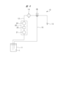
- the liquid supply device 10 shown in FIG. 1 is used to apply a liquid L such as a photoresist liquid stored in a liquid tank 11 serving as a liquid storage portion to an object to be coated such as a semiconductor wafer.
- the liquid supply device 10 has a liquid supply path 12 made of piping, a hose, etc., an applicator 13 such as a nozzle is provided at the tip of the liquid supply path 12, and a base end of the liquid supply path 12 is provided with a liquid supply path 12. It is connected to tank 11.
- a pump unit 20 is provided in the liquid supply path 12, the pump unit 20 has two pumps 21, 22, and the two pumps 21, 22 are provided in series in the liquid supply path 12. .
- the pump 21 installed on the upstream side of the liquid supply path 12 be a first pump
- the pump 22 installed on the downstream side be a second pump. Both pumps 21 and 22 supply the liquid in the liquid tank 11 to the applicator 13.
- a flow path opening/closing valve 23 is provided between the first pump 21 and the second pump 22, and the flow path opening/closing valve 23 has a closed position where communication between the first pump 21 and the second pump is cut off, and a closed position where communication between the first pump 21 and the second pump is interrupted, and a closed position where the communication between the first pump 21 and the second pump is interrupted. It can be switched to the open position.
- a filter 14 for filtering the liquid discharged from the pump 22 is provided in the liquid supply path 12 at a position downstream of the pump 22.
- a return flow path 15 is provided between the liquid supply path 12 and the liquid tank 11 in order to return the liquid that has passed through the filter 14 to the liquid tank 11 .
- a connecting portion 16 that connects the return flow path 15 and the liquid supply path 12 is provided in the liquid supply path 12 located downstream of the filter 14 .
- a coating valve 24 is provided between the connecting portion 16 and the applicator 13, and the coating valve 24 communicates the flow path between the second pump 22 and the applicator 13 via the filter 14 to supply liquid. It opens and closes between an open state in which liquid is supplied to the applicator 13 and a closed state in which communication with the flow path is interrupted to stop the supply of liquid.
- a circulation valve 25 is provided in the return flow path 15, and the circulation valve 25 connects the flow path between the liquid supply path 12 and the liquid tank 11 via the return flow path 15 to supply the liquid to the liquid tank 11. It opens and closes between an open state in which it returns and a closed state in which it blocks the return flow path 15.
- the application valve 24 When the application valve 24 is opened, that is, turned on, and the circulation valve 25 is closed, that is, turned off, the liquid discharged from the second pump 22 and filtered by the filter 14 passes through the application valve 24 and is delivered to the applicator. 13. In this way, supplying the liquid to the applicator 13 and stopping the supply of the liquid to the return channel 15 is defined as the application mode.
- the application valve 24 is closed, ie, turned OFF, and the circulation valve 25 is opened, ie, turned ON, the liquid filtered by the filter 14 flows through the return channel 15 and is returned to the liquid tank 11. Supplying the liquid to the return channel 15 and stopping the supply of the liquid to the applicator 13 in this manner is defined as the circulation mode.
- the liquid supply device 10 can operate in either the application mode or the circulation mode, when the liquid is not being applied from the applicator 13, the liquid can be returned to the liquid tank 11 via the return channel 15. I can do it. As a result, the liquid passes through the filter 14 multiple times and is filtered, so that foreign substances such as microparticles, particles, and air bubbles contained in the liquid are removed by the filter 14, thereby reducing the amount of foreign substances contained in the liquid. can.
- the filter 14 may be arranged between the connection part 16 of the return channel 15 and the circulation valve 25 as shown in FIG. In this case, since it is not affected by the filter 14, it is possible to apply liquid with reduced foreign matter with higher ejection accuracy. When the filter 14 is disposed in the return flow path 15, it is preferable to operate it in the circulation mode for a certain period of time and then operate it in the coating mode, since this allows the liquid with reduced foreign matter to be supplied to the applicator 13.
- FIG. 2 is a partially cutaway side view showing an example of the pump unit 20 that constitutes the liquid supply device 10.
- 3 is an enlarged sectional view showing the main part of FIG. 2
- FIG. 4 is a sectional view taken along the line AA in FIG.
- the pump unit 20 has a pump block 31 in the shape of a rectangular parallelepiped.
- the pump block 31 has six faces, and in FIGS. 2 and 3, the left side is a front face 31a, the opposite side is a back face 31b, the lower face is a lower end face 31c, and the upper face is an upper end face. 31d.
- the left and right surfaces are referred to as side surfaces 31e and 31f.
- the front surface 31a and the back surface 31b are parallel, and the lower end surface 31c and the upper end surface 31d are parallel and perpendicular to the front surface 31a and the back surface 31b.
- a first cylinder hole 32 with a bottom is provided in the pump block 31 and opens on the back surface 31b
- a second cylinder hole 33 with a bottom is provided in the pump block 31 and opens on the back surface 31b. Both cylinder bores 32, 33 are parallel to each other.
- the pump block 31 is an integral type in which the two cylinder holes 32 and 33 are integrally formed in a single block member.
- the front surface 31a and the upper and lower end surfaces 31c and 31d are external surfaces exposed to the outside.
- the back surface 31b of the pump block 31 is a drive mechanism mounting surface, and the pump drive mechanism 34 is mounted on the back surface 31b.
- the pump drive mechanism 34 drives the first pump 21 and the second pump 22.
- the pump 21 has a plunger 35 as a pump member
- the pump 22 has a plunger 36 as a pump member.
- the plunger 35 is attached to the cylinder hole 32 so as to be able to reciprocate.
- the first pump chamber 21a is formed by the cylinder hole 32 and the plunger 35, and the pump chamber 21a is expanded and contracted by the reciprocation of the plunger 35.
- the contraction limit position of the plunger 35 is set by the position where the plunger 35 is closest to the bottom surface of the first cylinder hole 32.
- the plunger 36 is attached to the cylinder hole 33 so as to be able to reciprocate.
- the second pump chamber 22a is formed by the cylinder hole 33 and the plunger 36, and the pump chamber 22a is expanded and contracted by the reciprocation of the plunger 36.
- the contraction limit position of the plunger 36 is set by the position where the plunger 36 is closest to the bottom surface of the cylinder hole 33. 2 and 3, the plunger 36 is shown closest to the bottom surface of the cylinder hole 33.
- a small gap is provided between the plunger 35 and the cylinder hole 32, and the seal member 37 prevents liquid from leaking from the pump chamber 21a. Similarly, the seal member 38 prevents liquid from leaking from the pump chamber 22a.
- a first suction passage 39 is formed in the pump block 31, and the suction passage 39 opens at the lower end surface 31c, which is an opening surface, and communicates with the pump chamber 21a.
- a first discharge passage 41 is formed in the pump block 31, and the discharge passage 41 opens on the front face 31a, which is a valve mounting surface, and communicates with the pump chamber 21a.
- the discharge flow path 41 includes a communication section 41a, which is a first communication section, and a discharge section 41b.
- the communication portion 41a communicates with the pump chamber 21a, is coaxial with the suction passage 39, and is perpendicular to the cylinder hole 32.
- the discharge portion 41b is parallel to the cylinder hole 32 and opens to the front surface 31a.
- a second suction passage 42 is formed in the pump block 31, and the suction passage 42 opens on the front face 31a, which is the mounting surface, and communicates with the pump chamber 22a.
- a second discharge passage 43 is formed in the pump block 31, and the discharge passage 43 opens at the upper end surface 31d, which is an opening surface, and communicates with the pump chamber 22a.
- the suction flow path 42 includes a communication section 42a, which is a second communication section, and a suction section 42b.
- the communication portion 42a communicates with the pump chamber 22a, is coaxial with the discharge passage 43, and is perpendicular to the cylinder hole 33.
- the suction portion 42b is parallel to the cylinder hole 33, parallel to the discharge portion 41b, and opens to the front surface 31a.
- the pump drive mechanism 34 includes a first motor 44 for reciprocating a plunger 35 as a pump member, and a second motor 45 for reciprocating a plunger 36 as a pump member.
- a nut screwed to the plunger 35 is built into the pump drive mechanism 34, and the rotational motion of the main shaft of the motor 44 is converted into linear reciprocating motion of the plunger 35 via the nut.
- the rotational motion of the main shaft of the motor 45 is converted into a linear reciprocating motion of the plunger 36.
- a flow path opening/closing electromagnetic valve 23a as the flow path opening/closing valve 23 shown in FIG. 1 is attached to the front face 31a as a valve mounting surface.
- the flow path opening/closing electromagnetic valve 23a blocks communication between the discharge flow path 41 and the suction flow path 42 when the pump 21 performs a suction operation and the pump 22 performs a discharge operation.
- the flow path opening/closing electromagnetic valve 23a allows the discharge flow path 41 and the suction flow path 42 to communicate with each other when the pump 22 performs a suction operation and the pump 21 performs a discharge operation.
- the liquid is supplied to the pump chamber 22 a by the discharge operation of the pump 21 , and the liquid is discharged from the pump chamber 22 a toward the filter 14 . That is, when the pump 21 performs a discharge operation and the pump 22 performs a suction operation, liquid is supplied from the pump chamber 21a to the pump chamber 22a via the flow path opening/closing electromagnetic valve 23a.
- the flow path opening/closing electromagnetic valve 23a is provided outside the pump block 31, and operates between an open state where the discharge flow path 41 and the suction flow path 42 communicate with each other, and a closed state where the communication is cut off. If the rotation direction of the motors 44, 45 when each pump 21, 22 performs a discharge operation is the forward rotation direction, then the motors 44, 45 are driven in the reverse direction when the pumps 21, 22 perform a suction operation.
- the discharge amount per unit time of the pump 21 is twice the suction amount per unit time of the pump 22, and when the flow path opening/closing solenoid valve 23a is open, the pump 21 discharges At the same time as the operation, the pump 22 performs a suction operation.
- the liquid in the pump chamber 21a flows into the pump chamber 22a and is discharged from the pump chamber 22a toward the filter 14. That is, when the plunger 36 of the pump 22 performs a suction operation and the plunger 35 of the pump 21 performs a discharge operation, the discharge operation of the plunger 35 causes the liquid in the pump chamber 21a to be supplied to the pump chamber 22a. It is discharged into the discharge flow path 43 through the discharge channel 43 .
- the discharge operation of discharging the liquid from the pump unit 20 includes a discharge pattern in which the liquid is discharged through the pump 22 by the discharge operation of the pump 21, and a discharge pattern in which the liquid is discharged by the discharge operation of the pump 22.
- the liquid flowing into the discharge flow path 43 flows in the flow path from the lower end surface to the upper end surface of the pump block 31, so even if the liquid supplied to the pump unit 20 contains air bubbles, the air bubbles will not flow into the flow path. Air bubbles can be discharged to the outside without remaining in the air.
- FIG. 5 is a sectional view showing a main part of the flow path opening/closing electromagnetic valve 23a shown in FIG. 2.
- the flow path opening/closing electromagnetic valve 23 a has a valve housing case 47 provided with a solenoid case 46 , and a port plate 48 is attached to the valve housing case 47 .
- the flow path opening/closing electromagnetic valve 23a has a valve driving section that opens and closes the valve member 49 to switch between an open state and a closed state based on a control signal from the outside.
- a movable core 50 serving as a valve drive unit is installed in the solenoid case 46 so as to be able to reciprocate in the axial direction, and a coil spring 51 applies a spring force to the movable core 50 in the direction of protruding toward the port plate 48.
- a coil (not shown) is incorporated in the solenoid case 46, and when a drive current as a control signal is applied to the coil, the movable iron core 50 is driven in a backward direction against the spring force.
- the port plate 48 is removably attached to the front surface 31a of the pump block 31 by a screw member 52, as shown in FIGS. 2 and 3.
- a screw attachment hole 52a into which the screw member 52 is attached is formed in the port plate 48.
- the swing arm 53 is arranged within the valve housing case 47, and the swing arm 53 extends in front of the movable core 50 in a direction that crosses the movable core 50.
- a base end portion of the swing arm 53 is swingably supported by the valve housing case 47 by a support shaft 54 .
- a valve drive lever 55 is disposed between the swing arm 53 and the port plate 48, and the valve drive lever 55 extends along the swing arm 53.
- a central portion in the longitudinal direction of the valve drive lever 55 is swingably supported within the valve housing case 47 by a support shaft 56, and the valve drive lever 55 swings around the support shaft 56.
- the valve member 49 is made of rubber and is provided on the valve drive lever 55, and a liquid flow path 57 is formed by the valve member 49 and the port plate 48.
- An inflow hole 58 and an outflow hole 59 are formed in the port plate 48 , and the inflow hole 58 and the outflow hole 59 are communicated with each other by a liquid flow path 57 .
- the inflow hole 58 communicates with the first discharge flow path 41
- the outflow hole 59 communicates with the second suction flow path 42 .
- An opening/closing part 49a is provided on the valve member 49 corresponding to the outflow hole 59, and the opening/closing part 49a opens and closes the outflow hole 59.
- a coil spring 60 is disposed between the base end of the swing arm 53 and one end of the valve drive lever 55, and the coil spring 60 applies a spring force to the valve drive lever 55 in the direction in which the opening/closing portion 49a opens the outflow hole 59.
- An actuating portion 53a is provided at the tip of the swing arm 53, and the actuating portion 53a is in contact with the other end of the valve drive lever 55.
- a force point portion 53b is provided at the center in the longitudinal direction of the swing arm 53, the force point portion 53b protrudes toward the movable iron core 50, and the tip end surface of the movable iron core 50 is in contact with the force point portion 53b. Since the movable core 50 is in contact with the central portion in the longitudinal direction of the swing arm 53, the swing stroke of the actuating portion 53a is expanded more than the axial stroke of the movable core 50, and the expanded swing of the actuating portion 53a The opening/closing portion 49a is opened/closed by the stroke. Therefore, the opening/closing portion 49a can open and close the outflow hole 59 at high speed while ensuring the degree of communication opening between the liquid flow path 57 and the outflow hole 59 using the small flow path opening/closing electromagnetic valve 23a.
- FIG. 5(A) shows a state in which the opening/closing portion 49a closes the outflow hole 59 and blocks communication between the inflow hole 58 and the outflow hole 59 due to the spring force of the coil spring 51, that is, the closed state.
- FIG. 5(B) shows that when a drive current is applied to the coil and the movable iron core 50 is driven backward, the opening/closing part 49a is separated from the outflow hole 59 by the spring force of the coil spring 60, and the inflow hole 58 and the outflow hole 59 are communicated with each other. In other words, it shows the open state.
- the flow path opening/closing solenoid valve 23a is provided outside the pump block 31 without being incorporated into the pump block 31, the flow path opening/closing solenoid valve 23a can be easily removed from the pump block 31 by loosening the screw member 52. This makes it possible to improve maintenance efficiency such as inspection and replacement of the flow path opening/closing electromagnetic valve 23a.
- a suction side valve 61 is provided on the lower end surface 31c as the first opening surface.
- the suction side valve 61 shown in FIG. 3 is a check valve.
- the suction side valve 61 has a valve case 62 attached to the lower end surface 31c, and a valve chamber 63 communicating with the first suction flow path 39 is provided in the valve case 62.
- a suction port 62a is provided in the valve case 62, and a suction side portion 12a of the liquid supply path 12 connected to the liquid tank 11 is connected to the suction port 62a.
- a valve body 64 made of a ball is provided in the valve chamber 63.
- the suction side valve 61 guides the liquid L contained in the liquid tank 11 to the pump chamber 21a during the suction operation of the plunger 35, and the valve body 64 closes the valve chamber 63 when the plunger 35 discharges the liquid L to the liquid tank 11. Prevent backflow of liquid.
- a discharge side valve 65 is provided on the upper end surface 31d as an opening surface.
- the discharge side valve 65 shown in FIG. 3 is a check valve like the suction side valve 61.
- the discharge side valve 65 has a valve case 66 attached to the upper end surface 31d, and the valve case 66 is provided with a valve chamber 67 that communicates with the discharge side portion 12b of the liquid supply path 12.
- a discharge port 66a is provided in the valve case 66, and the discharge side portion 12b is connected to the discharge port 66a.
- a valve body 68 made of a ball is provided within the valve chamber 67. In the discharge side valve 65, when the liquid supply device 10 is stopped, the valve body 68 closes the valve chamber 67 to prevent liquid dripping from the applicator 13.
- FIG. 6 is a block diagram showing a control circuit of the liquid supply device 10, in which the motor 44 of the first pump 21, the motor 45 of the second pump 22, the flow path opening/closing electromagnetic valve 23a, the application valve 24, and the circulation
- the operation of the valve 25 is controlled by a control section 70.
- the control unit 70 is connected to an operation panel 69, and operation of the liquid supply device 10 is started by a command key (not shown) provided on the operation panel 69.
- the control unit 70 includes a microprocessor that calculates control signals, a memory that stores a control program, and the like.
- the control unit 70 controls the operations of the pumps 21, 22 and the valves 23a, 24, 25, and sets the liquid supply device 10 to a coating mode and a circulation mode.
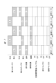
- FIG. 7 is a time chart showing an example of a driving mode of the pump for supplying liquid to the applicator 13 by the liquid supply device 10.
- three application modes 1, 2, and 3 and two circulation modes 1 and 2 are shown.
- the liquid discharge operation from the pump unit 20 to the filter 14 includes a first discharge pattern based on the discharge operation of the first pump 21 and a second discharge pattern based on the discharge operation of the second pump 22.
- first discharge pattern liquid is supplied to the pump chamber 22a of the second pump 22. This discharge operation is common to both application mode and circulation mode.
- liquid is continuously supplied to the applicator 13 via the filter 14 by the second discharge pattern by the pump 22.
- the circulation mode 1 after the application mode 1 ends, the application mode 1 ends with the second ejection pattern, so in the circulation mode 1, the circulation mode 1 is executed using the first ejection pattern.
- circulation mode 2 is performed subsequent to circulation mode 1, the ejection pattern is switched to the second ejection pattern.
- coating mode 3 is performed after circulation mode 2, the coating pattern is switched to the first coating pattern. In this way, in the circulation mode, one of the first pump 21 and the second pump 22 performs the discharge operation, and the liquid of the return flow rate is continuously caused to flow into the return flow path 15.
- the coating mode 3 is further performed following the coating mode 2, since the liquid was applied by the second discharge pattern in the coating mode 2, the liquid is applied to the applicator 13 by the first discharge pattern as shown in FIG. Supplied.
- the application mode is repeated multiple times, the first discharge pattern and the second discharge pattern are alternately performed.
- the circulation mode 2 is performed next to the application mode 3 in the first discharge pattern, it is switched to the second discharge pattern.
- the coating mode a predetermined amount of liquid is discharged onto the object to be coated from either the first pump 21 or the second pump 22.
- the circulation mode one of the first pump 21 and the second pump 22 causes the liquid to flow continuously into the return channel 15 .
- the first pump 21 and the second pump 2 alternately return the liquid and continuously flow the liquid into the channel. Further, it is also possible to switch to the circulation mode after repeating the coating mode a plurality of times, and it is also possible to perform the circulation mode once or multiple times after executing the coating mode once.
- the times in the application mode and circulation mode shown in FIG. 7 are the time during which the plunger 35 moves by a stroke S1, and the time during which the plunger 36 moves by a stroke S2, and are the same time.
- the circulation mode is repeated twice, but it may be repeated three or more times, or the application mode and circulation mode may be switched every time.
- FIG. 8 is a schematic diagram showing a liquid supply device 10 according to another embodiment.
- This liquid supply device 10 is not provided with the application valve 24 and the circulation valve 25 shown in FIG.
- a three-way valve 26 is provided at the connection between the return channel 15 and the liquid supply channel 12. It constitutes a switching means for switching to one of the circulation modes.
- the filter 14 may be arranged in the return channel 15.
- FIG. 9 is a sectional view showing the main parts of a pump unit 20 that is a modified example.
- the cross-sectional area of the first cylinder hole 32 formed in the pump block 31 in FIG. 9 is set to be twice the cross-sectional area of the second cylinder hole 33. Therefore, by making the reciprocating stroke S1 of the plunger 35 and the reciprocating stroke S2 of the plunger 36 the same, the amount of liquid discharged from the pump chamber 21a by the plunger 35 is equal to that of the pump unit 20 shown in FIGS. 2 and 3. Similarly, the amount of liquid discharged from the pump chamber 22a is set by the plunger 36 to be twice the amount of liquid discharged from the pump chamber 22a.
- the liquid supply device 10 equipped with the pump unit 20 shown in FIG. 9 can also operate in a coating mode and a circulation mode, as shown in FIG.
- FIG. 10 is a sectional view showing a pump unit 20 that is another modification.
- the suction side port block 71 is attached to the lower end surface 31c, which is the opening surface of the pump block 31, and the discharge side port block 72 is attached to the upper end surface 31d, which is the opening surface of the pump block 31.
- the port block 71 has a discharge passage 73 communicating with the suction passage 39 and a suction passage 74 communicating with the suction port 71a, and similarly to the liquid supply device 10 shown in FIG.
- the suction side portion 12a of the suction side portion 12a is connected to the suction port 71a.
- a suction side electromagnetic valve 61 a serving as the suction side valve 61 is attached to the port block 71 .
- the suction side electromagnetic valve 61a has the same structure as the passage opening/closing electromagnetic valve 23a, and the suction passage 74 communicates with the inflow hole of the suction side electromagnetic valve 61a, and the discharge passage 73 communicates with the outflow hole.
- the suction-side electromagnetic valve 61a has an open state in which the suction flow path 74 and the discharge flow path 73 communicate with each other and the first suction flow path 39 and the suction port 71a, and a closed state in which communication is interrupted. It is operated by a drive signal applied from the outside.
- the discharge side port block 72 has a suction passage 75 communicating with the discharge passage 43 and a discharge passage 76 communicating with the discharge port 72a, and is similar to the pump unit 20 shown in FIGS. 2 and 3.
- the discharge side portion 12b of the liquid supply path 12 is connected to the discharge port 72a.
- a discharge side electromagnetic valve 65a serving as the discharge side valve 65 is attached to the port block 72.
- the discharge side solenoid valve 65a has the same structure as the passage opening/closing solenoid valve 23a and the suction side solenoid valve 61a, and communicates between the suction passage 75 and the discharge passage 76, and connects the second discharge passage 43 and the discharge passage. It is operated by a drive signal applied from the outside in an open state in which it communicates with the port 72a and in a closed state in which communication is cut off.
- the suction side solenoid valve 61a and the discharge side solenoid valve 65a are solenoid valves that switch between an open state and a closed state based on an external control signal.
- the suction side valve 61 and the discharge side valve 65 are check valves that prevent backflow.
- one of the suction side valve 61 and the discharge side valve 65 may be an electromagnetic valve, and the other may be a check valve.
- FIG. 11 is a time chart showing an example of the driving mode of the pump unit 20, which includes the suction side electromagnetic valve 61a and the discharge side electromagnetic valve 65a, as shown in FIG.
- the suction side electromagnetic valve 61a in both the coating mode and the circulation mode, the suction side electromagnetic valve 61a is turned OFF during the first discharge pattern in which liquid is discharged toward the filter 14 by the discharge operation of the first pump 21. is set to On the other hand, in the second discharge pattern in which liquid is discharged toward the filter 14 by the discharge operation of the second pump 22, the suction side electromagnetic valve 61a is set to ON.
- FIG. 12 is a sectional view showing a modification of the pump that forms the pump unit 20.
- FIG. 12 shows a tube flamm pump 81, and the tube flamm pump 81 can be used in place of the first pump 21 and second pump 22, which are piston pumps described above.
- the discharge capacities are different from each other such that the discharge volume of the tube phragm pump 81 constituting the first pump 21 is twice the discharge volume of the tube phram pump 81 constituting the second pump 22.
- the tube flamm pump 81 includes a cylindrical storage container 82 as a storage member, an inflow side joint member 83 provided at one end of the container, and an outflow side joint member 84 provided at the other end. There is.
- the suction side portion 12a of the liquid supply path 12 is connected to the inflow side joint member 83, and the discharge side portion 12b is connected to the outflow side joint member 84.
- a flexible tube, that is, a tube flammable 85, is provided in the container 82, and the tube flammable 85 has an inflow-side fixed end 85a fixed to the inflow-side joint member 83, and an outflow-side joint member 84.
- the joint members 83 and 84 and the tube flamm 85 are each made of synthetic resin such as fluororesin.
- the tube flamm 85 is partitioned into a pump chamber 86 on the inside and a liquid storage chamber 87 on the outside, and the liquid storage chamber 87 is formed between the tube flamm 85 and the storage container 82 .
- the liquid storage chamber 87 is filled with an incompressible liquid as a liquid medium M, and the liquid medium M is supplied from the outside to the liquid storage chamber 87 through a supply/discharge port 88 formed in the storage container 82.
- a supply/discharge pump 89 is connected to the supply/discharge port 88 .
- This supply/discharge pump 89 has a bellows 92 attached to a rod 91 that reciprocates linearly, and the rod 91 is driven in the axial direction by a driving member such as an electric motor or a pneumatic cylinder.
- a liquid storage chamber 93 outside the bellows 92 is also filled with a liquid medium, and the liquid medium M communicates the liquid storage chamber 93 with the liquid storage chamber 87 of the tube flamm pump 81 .
- the elastic deformation portion 85c of the tube flammable 85 is deformed in the radial direction by the liquid medium in the liquid storage chamber 87.
- the pump chamber 86 contracts.
- the elastic deformation portion 85c expands in the radial direction, and the pump chamber 86 expands.
- a check valve 94 is provided on the suction side 12a of the liquid supply path 12, and a check valve 95 is provided on the discharge side 12b.
- the pump chamber 86 contracts, the liquid L flows out from the pump chamber 86 toward the discharge side portion 12b. At this time, backflow of liquid to the suction side portion 12a is prevented. It is also possible to incorporate the check valve 94 into the joint member 83 and the check valve 95 into the joint member 84. Further, the liquid medium M may be supplied to and discharged from the liquid storage chamber 87 by the rod 91 without providing the bellows 92 in the supply and discharge pump 89.
- the liquid supply device 10 can be driven as shown in FIGS. 7 and 11.
- FIG. 13 is a schematic diagram showing a liquid supply device according to still another embodiment.
- the filter 14 is arranged in the return channel 15, as described above.
- each pump may be not only a piston pump, a tube flamm pump, but also a bellows pump.
- the filter 14 When the filter 14 is disposed in the return flow path 15, the filter 14 may be provided downstream of the circulation valve 25 or upstream thereof.
- the times in the coating mode and the circulation mode are the same, the times in the coating mode and the circulation mode may be different depending on the flow rate suitable for coating or the flow rate suitable for circulation.
- This liquid supply device is applied to supply a liquid to an object to be coated, such as when applying a chemical liquid such as a photoresist liquid to a semiconductor wafer.
Landscapes
- Engineering & Computer Science (AREA)
- Mechanical Engineering (AREA)
- General Engineering & Computer Science (AREA)
- Coating Apparatus (AREA)
- Details Of Reciprocating Pumps (AREA)
- Nozzles (AREA)
Priority Applications (3)
| Application Number | Priority Date | Filing Date | Title |
|---|---|---|---|
| CN202280093537.XA CN118871669A (zh) | 2022-03-30 | 2022-10-24 | 液体供给装置 |
| JP2024511183A JPWO2023188488A1 (https=) | 2022-03-30 | 2022-10-24 | |
| KR1020247030410A KR20240165345A (ko) | 2022-03-30 | 2022-10-24 | 액체 공급 장치 |
Applications Claiming Priority (2)
| Application Number | Priority Date | Filing Date | Title |
|---|---|---|---|
| JP2022-056396 | 2022-03-30 | ||
| JP2022056396 | 2022-03-30 |
Publications (1)
| Publication Number | Publication Date |
|---|---|
| WO2023188488A1 true WO2023188488A1 (ja) | 2023-10-05 |
Family
ID=88200605
Family Applications (1)
| Application Number | Title | Priority Date | Filing Date |
|---|---|---|---|
| PCT/JP2022/039529 Ceased WO2023188488A1 (ja) | 2022-03-30 | 2022-10-24 | 液体供給装置 |
Country Status (5)
| Country | Link |
|---|---|
| JP (1) | JPWO2023188488A1 (https=) |
| KR (1) | KR20240165345A (https=) |
| CN (1) | CN118871669A (https=) |
| TW (1) | TW202337568A (https=) |
| WO (1) | WO2023188488A1 (https=) |
Citations (5)
| Publication number | Priority date | Publication date | Assignee | Title |
|---|---|---|---|---|
| JP2000120530A (ja) * | 1998-10-13 | 2000-04-25 | Koganei Corp | 薬液供給方法および薬液供給装置 |
| JP2008018310A (ja) * | 2006-07-11 | 2008-01-31 | Koganei Corp | 薬液供給装置および薬液供給方法 |
| JP2011101851A (ja) * | 2009-11-11 | 2011-05-26 | Koganei Corp | 薬液供給装置および薬液供給方法 |
| JP2014001663A (ja) * | 2012-06-18 | 2014-01-09 | Koganei Corp | 液体供給装置 |
| JP2020002881A (ja) * | 2018-06-28 | 2020-01-09 | 株式会社コガネイ | 液体供給装置および液体供給方法 |
Family Cites Families (1)
| Publication number | Priority date | Publication date | Assignee | Title |
|---|---|---|---|---|
| JP4124712B2 (ja) | 2003-09-11 | 2008-07-23 | 株式会社コガネイ | 薬液供給用の可撓性チューブ |
-
2022
- 2022-10-24 KR KR1020247030410A patent/KR20240165345A/ko active Pending
- 2022-10-24 CN CN202280093537.XA patent/CN118871669A/zh active Pending
- 2022-10-24 WO PCT/JP2022/039529 patent/WO2023188488A1/ja not_active Ceased
- 2022-10-24 JP JP2024511183A patent/JPWO2023188488A1/ja active Pending
- 2022-11-01 TW TW111141506A patent/TW202337568A/zh unknown
Patent Citations (5)
| Publication number | Priority date | Publication date | Assignee | Title |
|---|---|---|---|---|
| JP2000120530A (ja) * | 1998-10-13 | 2000-04-25 | Koganei Corp | 薬液供給方法および薬液供給装置 |
| JP2008018310A (ja) * | 2006-07-11 | 2008-01-31 | Koganei Corp | 薬液供給装置および薬液供給方法 |
| JP2011101851A (ja) * | 2009-11-11 | 2011-05-26 | Koganei Corp | 薬液供給装置および薬液供給方法 |
| JP2014001663A (ja) * | 2012-06-18 | 2014-01-09 | Koganei Corp | 液体供給装置 |
| JP2020002881A (ja) * | 2018-06-28 | 2020-01-09 | 株式会社コガネイ | 液体供給装置および液体供給方法 |
Also Published As
| Publication number | Publication date |
|---|---|
| KR20240165345A (ko) | 2024-11-22 |
| TW202337568A (zh) | 2023-10-01 |
| JPWO2023188488A1 (https=) | 2023-10-05 |
| CN118871669A (zh) | 2024-10-29 |
Similar Documents
| Publication | Publication Date | Title |
|---|---|---|
| KR102591031B1 (ko) | 액체공급장치 및 액체공급방법 | |
| JP4566955B2 (ja) | 薬液供給装置および薬液供給方法 | |
| JP7578535B2 (ja) | 液体供給装置 | |
| JP5038378B2 (ja) | 薬液供給装置および薬液供給方法 | |
| US5807085A (en) | Liquid medicine supplying system with valve devices | |
| JP5114527B2 (ja) | 液体供給装置 | |
| KR101391070B1 (ko) | 약액 공급 장치 | |
| JP4422040B2 (ja) | 弁装置 | |
| WO2023188488A1 (ja) | 液体供給装置 | |
| JP4454350B2 (ja) | 薬液供給装置 | |
| JP3619616B2 (ja) | 薬液供給装置の駆動方法 | |
| JPH1047234A (ja) | 定量吐出ポンプ | |
| JP7527669B2 (ja) | ダイアフラムポンプ | |
| JP4701257B2 (ja) | 液体ポンプシステム | |
| JP2001234849A (ja) | 往復動型ポンプ | |
| CN120592853A (zh) | 喷涂设备液压缸的往复运动控制机构及喷涂设备 | |
| JP2017031881A (ja) | 液体供給装置 | |
| JPWO2005088129A1 (ja) | 薬液供給装置 | |
| JP4610582B2 (ja) | 液体ポンプシステム | |
| JP4756008B2 (ja) | 液体ポンプ装置の駆動方法 | |
| JP2001153034A (ja) | 液体吐出ポンプ | |
| JPH1193830A (ja) | 超磁歪式液体ポンプ | |
| JP2005147095A (ja) | 薬液供給装置 | |
| JPH0396669A (ja) | エアハイドロ出力圧制御ポンプ |
Legal Events
| Date | Code | Title | Description |
|---|---|---|---|
| 121 | Ep: the epo has been informed by wipo that ep was designated in this application |
Ref document number: 22935619 Country of ref document: EP Kind code of ref document: A1 |
|
| ENP | Entry into the national phase |
Ref document number: 2024511183 Country of ref document: JP Kind code of ref document: A |
|
| WWE | Wipo information: entry into national phase |
Ref document number: 202280093537.X Country of ref document: CN |
|
| NENP | Non-entry into the national phase |
Ref country code: DE |
|
| 122 | Ep: pct application non-entry in european phase |
Ref document number: 22935619 Country of ref document: EP Kind code of ref document: A1 |