WO2023188488A1 - 液体供給装置 - Google Patents
液体供給装置 Download PDFInfo
- Publication number
- WO2023188488A1 WO2023188488A1 PCT/JP2022/039529 JP2022039529W WO2023188488A1 WO 2023188488 A1 WO2023188488 A1 WO 2023188488A1 JP 2022039529 W JP2022039529 W JP 2022039529W WO 2023188488 A1 WO2023188488 A1 WO 2023188488A1
- Authority
- WO
- WIPO (PCT)
- Prior art keywords
- pump
- liquid
- flow path
- valve
- supply device
- Prior art date
Links
- 239000007788 liquid Substances 0.000 title claims abstract description 246
- 230000004087 circulation Effects 0.000 claims description 50
- 239000011248 coating agent Substances 0.000 claims description 24
- 238000000576 coating method Methods 0.000 claims description 24
- 238000007599 discharging Methods 0.000 claims description 2
- 239000000126 substance Substances 0.000 description 10
- 238000010586 diagram Methods 0.000 description 7
- XEEYBQQBJWHFJM-UHFFFAOYSA-N Iron Chemical group [Fe] XEEYBQQBJWHFJM-UHFFFAOYSA-N 0.000 description 4
- 238000012986 modification Methods 0.000 description 4
- 230000004048 modification Effects 0.000 description 4
- 238000011144 upstream manufacturing Methods 0.000 description 4
- 229920002120 photoresistant polymer Polymers 0.000 description 3
- 239000004065 semiconductor Substances 0.000 description 3
- 230000008602 contraction Effects 0.000 description 2
- 230000005489 elastic deformation Effects 0.000 description 2
- 238000012423 maintenance Methods 0.000 description 2
- 239000011859 microparticle Substances 0.000 description 2
- 239000002245 particle Substances 0.000 description 2
- 239000004642 Polyimide Substances 0.000 description 1
- 239000003570 air Substances 0.000 description 1
- 239000003814 drug Substances 0.000 description 1
- 229940079593 drug Drugs 0.000 description 1
- 238000001914 filtration Methods 0.000 description 1
- 238000007689 inspection Methods 0.000 description 1
- 229920001721 polyimide Polymers 0.000 description 1
- 229920003002 synthetic resin Polymers 0.000 description 1
- 239000000057 synthetic resin Substances 0.000 description 1
Images


Classifications
-
- F—MECHANICAL ENGINEERING; LIGHTING; HEATING; WEAPONS; BLASTING
- F04—POSITIVE - DISPLACEMENT MACHINES FOR LIQUIDS; PUMPS FOR LIQUIDS OR ELASTIC FLUIDS
- F04B—POSITIVE-DISPLACEMENT MACHINES FOR LIQUIDS; PUMPS
- F04B23/00—Pumping installations or systems
- F04B23/04—Combinations of two or more pumps
- F04B23/06—Combinations of two or more pumps the pumps being all of reciprocating positive-displacement type
Definitions
- the present invention relates to a liquid supply device for supplying a liquid such as a chemical to an object to be coated.
- a liquid supply device for supplying liquid contained in a liquid container to an object to be supplied includes a pump.
- the drug solution supply devices described in Patent Document 1 and Patent Document 2 include a pump made of a tube flammable tube, which is a flexible tube that can be expanded and contracted in the radial direction.
- a chemical liquid such as a photoresist liquid or a polyimide liquid contained in a liquid container passes through a filter and is supplied to the surface of a semiconductor wafer as an object to be coated by a pump.
- Pumps that can be applied to liquid supply devices include not only tube-flamm pumps, but also bellows pumps with flexible bellows that can be expanded and contracted in the axial direction, and piston pumps in which a piston is attached to a cylinder so that it can reciprocate. There is. Small piston pumps are also called syringe pumps.
- the chemical liquid supply device described in Patent Document 1 has a return flow path for returning the liquid discharged from a single pump to the upstream side of the liquid supply path or to the liquid container, and the liquid is applied from the applicator. When not, the liquid can be returned upstream via the return channel. In this way, the liquid passes through the filter multiple times and is filtered, so the filter removes foreign substances such as micro particles, particles and bubbles contained in the liquid, and removes foreign substances contained in the liquid applied to the object to be coated. can be reduced.
- the pump In a chemical liquid supply device equipped with a single pump, in order to increase the number of liquid circulations, it is necessary to increase the flow rate of the liquid within a limited time.
- the pump has a structure optimized for the amount of coating applied to the object to be coated or the coating operation, and there is a limit to increasing the flow rate of this type of pump.
- An object of the present invention is to increase the amount of liquid circulating in a liquid supply path provided with a filter, and to increase the amount of foreign matter contained in the liquid reduced.
- the liquid supply device of the present invention is a liquid supply device that supplies a liquid contained in a liquid storage portion to an applicator that applies liquid to an object to be coated, and wherein the liquid contained in the liquid storage portion is applied to the application tool.
- a first pump and a second pump each provided in a liquid supply path that supplies the applicator, a filter that filters the liquid flowing toward the applicator, and a return that returns the liquid that has passed through the filter to the liquid storage section.
- a flow path is provided between the first pump and the second pump, and is in either a closed state in which communication between the first pump and the second pump is cut off, or an open state in which communication is established between the first pump and the second pump.
- a flow path opening/closing valve that switches to a coating mode that supplies liquid to the applicator and stops supplying liquid to the return flow path; and a coating mode that supplies liquid to the return flow path and stops supplying liquid to the applicator.
- a control unit configured to switch to either one of the circulation modes, in which in the application mode, one of the first pump and the second pump discharges the liquid to the object to be coated, and in the circulation mode, One of the first pump and the second pump discharges liquid to the return channel, and the first pump and the second pump continuously discharge liquid.
- the liquid In the circulation mode, the liquid is continuously circulated in the return channel, and the liquid returned to the liquid storage section by the return channel is supplied to the liquid supply channel, so that the liquid passes through the filter multiple times, and the liquid It is possible to reduce foreign substances contained in Since the first and second pumps are provided, the liquid can be constantly circulated in the circulation mode, and the discharge amount can be controlled with high precision in the application mode.
- FIG. 1 is a schematic diagram showing a liquid supply device according to an embodiment.
- FIG. 2 is a partially cutaway side view showing an example of a pump unit constituting the liquid supply device.
- FIG. 3 is an enlarged sectional view showing the main part of FIG. 2;
- FIG. 4 is a cross-sectional view taken along line AA in FIG. 3.
- 3 is a cross-sectional view showing the main parts of the flow path opening/closing solenoid valve shown in FIG. 2, (A) shows the state where the flow path opening/closing solenoid valve is closed, and (B) shows the state where the flow path opening/closing solenoid valve is open. show.
- FIG. 2 is a block diagram showing a control circuit of the liquid supply device.
- FIG. 7 is a schematic diagram showing a liquid supply device according to another embodiment.
- FIG. 7 is a partially cutaway side view showing main parts of a modified example of the pump unit.
- FIG. 7 is a partially cutaway side view showing another modification of the pump unit.
- 11 is a time chart showing an example of a driving mode of the pump unit shown in FIG. 10.
- FIG. It is a sectional view showing a modification of the pump which constitutes a pump unit.
- It is a schematic diagram showing a liquid supply device which is still another embodiment.
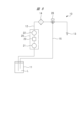
- the liquid supply device 10 shown in FIG. 1 is used to apply a liquid L such as a photoresist liquid stored in a liquid tank 11 serving as a liquid storage portion to an object to be coated such as a semiconductor wafer.
- the liquid supply device 10 has a liquid supply path 12 made of piping, a hose, etc., an applicator 13 such as a nozzle is provided at the tip of the liquid supply path 12, and a base end of the liquid supply path 12 is provided with a liquid supply path 12. It is connected to tank 11.
- a pump unit 20 is provided in the liquid supply path 12, the pump unit 20 has two pumps 21, 22, and the two pumps 21, 22 are provided in series in the liquid supply path 12. .
- the pump 21 installed on the upstream side of the liquid supply path 12 be a first pump
- the pump 22 installed on the downstream side be a second pump. Both pumps 21 and 22 supply the liquid in the liquid tank 11 to the applicator 13.
- a flow path opening/closing valve 23 is provided between the first pump 21 and the second pump 22, and the flow path opening/closing valve 23 has a closed position where communication between the first pump 21 and the second pump is cut off, and a closed position where communication between the first pump 21 and the second pump is interrupted, and a closed position where the communication between the first pump 21 and the second pump is interrupted. It can be switched to the open position.
- a filter 14 for filtering the liquid discharged from the pump 22 is provided in the liquid supply path 12 at a position downstream of the pump 22.
- a return flow path 15 is provided between the liquid supply path 12 and the liquid tank 11 in order to return the liquid that has passed through the filter 14 to the liquid tank 11 .
- a connecting portion 16 that connects the return flow path 15 and the liquid supply path 12 is provided in the liquid supply path 12 located downstream of the filter 14 .
- a coating valve 24 is provided between the connecting portion 16 and the applicator 13, and the coating valve 24 communicates the flow path between the second pump 22 and the applicator 13 via the filter 14 to supply liquid. It opens and closes between an open state in which liquid is supplied to the applicator 13 and a closed state in which communication with the flow path is interrupted to stop the supply of liquid.
- a circulation valve 25 is provided in the return flow path 15, and the circulation valve 25 connects the flow path between the liquid supply path 12 and the liquid tank 11 via the return flow path 15 to supply the liquid to the liquid tank 11. It opens and closes between an open state in which it returns and a closed state in which it blocks the return flow path 15.
- the application valve 24 When the application valve 24 is opened, that is, turned on, and the circulation valve 25 is closed, that is, turned off, the liquid discharged from the second pump 22 and filtered by the filter 14 passes through the application valve 24 and is delivered to the applicator. 13. In this way, supplying the liquid to the applicator 13 and stopping the supply of the liquid to the return channel 15 is defined as the application mode.
- the application valve 24 is closed, ie, turned OFF, and the circulation valve 25 is opened, ie, turned ON, the liquid filtered by the filter 14 flows through the return channel 15 and is returned to the liquid tank 11. Supplying the liquid to the return channel 15 and stopping the supply of the liquid to the applicator 13 in this manner is defined as the circulation mode.
- the liquid supply device 10 can operate in either the application mode or the circulation mode, when the liquid is not being applied from the applicator 13, the liquid can be returned to the liquid tank 11 via the return channel 15. I can do it. As a result, the liquid passes through the filter 14 multiple times and is filtered, so that foreign substances such as microparticles, particles, and air bubbles contained in the liquid are removed by the filter 14, thereby reducing the amount of foreign substances contained in the liquid. can.
- the filter 14 may be arranged between the connection part 16 of the return channel 15 and the circulation valve 25 as shown in FIG. In this case, since it is not affected by the filter 14, it is possible to apply liquid with reduced foreign matter with higher ejection accuracy. When the filter 14 is disposed in the return flow path 15, it is preferable to operate it in the circulation mode for a certain period of time and then operate it in the coating mode, since this allows the liquid with reduced foreign matter to be supplied to the applicator 13.
- FIG. 2 is a partially cutaway side view showing an example of the pump unit 20 that constitutes the liquid supply device 10.
- 3 is an enlarged sectional view showing the main part of FIG. 2
- FIG. 4 is a sectional view taken along the line AA in FIG.
- the pump unit 20 has a pump block 31 in the shape of a rectangular parallelepiped.
- the pump block 31 has six faces, and in FIGS. 2 and 3, the left side is a front face 31a, the opposite side is a back face 31b, the lower face is a lower end face 31c, and the upper face is an upper end face. 31d.
- the left and right surfaces are referred to as side surfaces 31e and 31f.
- the front surface 31a and the back surface 31b are parallel, and the lower end surface 31c and the upper end surface 31d are parallel and perpendicular to the front surface 31a and the back surface 31b.
- a first cylinder hole 32 with a bottom is provided in the pump block 31 and opens on the back surface 31b
- a second cylinder hole 33 with a bottom is provided in the pump block 31 and opens on the back surface 31b. Both cylinder bores 32, 33 are parallel to each other.
- the pump block 31 is an integral type in which the two cylinder holes 32 and 33 are integrally formed in a single block member.
- the front surface 31a and the upper and lower end surfaces 31c and 31d are external surfaces exposed to the outside.
- the back surface 31b of the pump block 31 is a drive mechanism mounting surface, and the pump drive mechanism 34 is mounted on the back surface 31b.
- the pump drive mechanism 34 drives the first pump 21 and the second pump 22.
- the pump 21 has a plunger 35 as a pump member
- the pump 22 has a plunger 36 as a pump member.
- the plunger 35 is attached to the cylinder hole 32 so as to be able to reciprocate.
- the first pump chamber 21a is formed by the cylinder hole 32 and the plunger 35, and the pump chamber 21a is expanded and contracted by the reciprocation of the plunger 35.
- the contraction limit position of the plunger 35 is set by the position where the plunger 35 is closest to the bottom surface of the first cylinder hole 32.
- the plunger 36 is attached to the cylinder hole 33 so as to be able to reciprocate.
- the second pump chamber 22a is formed by the cylinder hole 33 and the plunger 36, and the pump chamber 22a is expanded and contracted by the reciprocation of the plunger 36.
- the contraction limit position of the plunger 36 is set by the position where the plunger 36 is closest to the bottom surface of the cylinder hole 33. 2 and 3, the plunger 36 is shown closest to the bottom surface of the cylinder hole 33.
- a small gap is provided between the plunger 35 and the cylinder hole 32, and the seal member 37 prevents liquid from leaking from the pump chamber 21a. Similarly, the seal member 38 prevents liquid from leaking from the pump chamber 22a.
- a first suction passage 39 is formed in the pump block 31, and the suction passage 39 opens at the lower end surface 31c, which is an opening surface, and communicates with the pump chamber 21a.
- a first discharge passage 41 is formed in the pump block 31, and the discharge passage 41 opens on the front face 31a, which is a valve mounting surface, and communicates with the pump chamber 21a.
- the discharge flow path 41 includes a communication section 41a, which is a first communication section, and a discharge section 41b.
- the communication portion 41a communicates with the pump chamber 21a, is coaxial with the suction passage 39, and is perpendicular to the cylinder hole 32.
- the discharge portion 41b is parallel to the cylinder hole 32 and opens to the front surface 31a.
- a second suction passage 42 is formed in the pump block 31, and the suction passage 42 opens on the front face 31a, which is the mounting surface, and communicates with the pump chamber 22a.
- a second discharge passage 43 is formed in the pump block 31, and the discharge passage 43 opens at the upper end surface 31d, which is an opening surface, and communicates with the pump chamber 22a.
- the suction flow path 42 includes a communication section 42a, which is a second communication section, and a suction section 42b.
- the communication portion 42a communicates with the pump chamber 22a, is coaxial with the discharge passage 43, and is perpendicular to the cylinder hole 33.
- the suction portion 42b is parallel to the cylinder hole 33, parallel to the discharge portion 41b, and opens to the front surface 31a.
- the pump drive mechanism 34 includes a first motor 44 for reciprocating a plunger 35 as a pump member, and a second motor 45 for reciprocating a plunger 36 as a pump member.
- a nut screwed to the plunger 35 is built into the pump drive mechanism 34, and the rotational motion of the main shaft of the motor 44 is converted into linear reciprocating motion of the plunger 35 via the nut.
- the rotational motion of the main shaft of the motor 45 is converted into a linear reciprocating motion of the plunger 36.
- a flow path opening/closing electromagnetic valve 23a as the flow path opening/closing valve 23 shown in FIG. 1 is attached to the front face 31a as a valve mounting surface.
- the flow path opening/closing electromagnetic valve 23a blocks communication between the discharge flow path 41 and the suction flow path 42 when the pump 21 performs a suction operation and the pump 22 performs a discharge operation.
- the flow path opening/closing electromagnetic valve 23a allows the discharge flow path 41 and the suction flow path 42 to communicate with each other when the pump 22 performs a suction operation and the pump 21 performs a discharge operation.
- the liquid is supplied to the pump chamber 22 a by the discharge operation of the pump 21 , and the liquid is discharged from the pump chamber 22 a toward the filter 14 . That is, when the pump 21 performs a discharge operation and the pump 22 performs a suction operation, liquid is supplied from the pump chamber 21a to the pump chamber 22a via the flow path opening/closing electromagnetic valve 23a.
- the flow path opening/closing electromagnetic valve 23a is provided outside the pump block 31, and operates between an open state where the discharge flow path 41 and the suction flow path 42 communicate with each other, and a closed state where the communication is cut off. If the rotation direction of the motors 44, 45 when each pump 21, 22 performs a discharge operation is the forward rotation direction, then the motors 44, 45 are driven in the reverse direction when the pumps 21, 22 perform a suction operation.
- the discharge amount per unit time of the pump 21 is twice the suction amount per unit time of the pump 22, and when the flow path opening/closing solenoid valve 23a is open, the pump 21 discharges At the same time as the operation, the pump 22 performs a suction operation.
- the liquid in the pump chamber 21a flows into the pump chamber 22a and is discharged from the pump chamber 22a toward the filter 14. That is, when the plunger 36 of the pump 22 performs a suction operation and the plunger 35 of the pump 21 performs a discharge operation, the discharge operation of the plunger 35 causes the liquid in the pump chamber 21a to be supplied to the pump chamber 22a. It is discharged into the discharge flow path 43 through the discharge channel 43 .
- the discharge operation of discharging the liquid from the pump unit 20 includes a discharge pattern in which the liquid is discharged through the pump 22 by the discharge operation of the pump 21, and a discharge pattern in which the liquid is discharged by the discharge operation of the pump 22.
- the liquid flowing into the discharge flow path 43 flows in the flow path from the lower end surface to the upper end surface of the pump block 31, so even if the liquid supplied to the pump unit 20 contains air bubbles, the air bubbles will not flow into the flow path. Air bubbles can be discharged to the outside without remaining in the air.
- FIG. 5 is a sectional view showing a main part of the flow path opening/closing electromagnetic valve 23a shown in FIG. 2.
- the flow path opening/closing electromagnetic valve 23 a has a valve housing case 47 provided with a solenoid case 46 , and a port plate 48 is attached to the valve housing case 47 .
- the flow path opening/closing electromagnetic valve 23a has a valve driving section that opens and closes the valve member 49 to switch between an open state and a closed state based on a control signal from the outside.
- a movable core 50 serving as a valve drive unit is installed in the solenoid case 46 so as to be able to reciprocate in the axial direction, and a coil spring 51 applies a spring force to the movable core 50 in the direction of protruding toward the port plate 48.
- a coil (not shown) is incorporated in the solenoid case 46, and when a drive current as a control signal is applied to the coil, the movable iron core 50 is driven in a backward direction against the spring force.
- the port plate 48 is removably attached to the front surface 31a of the pump block 31 by a screw member 52, as shown in FIGS. 2 and 3.
- a screw attachment hole 52a into which the screw member 52 is attached is formed in the port plate 48.
- the swing arm 53 is arranged within the valve housing case 47, and the swing arm 53 extends in front of the movable core 50 in a direction that crosses the movable core 50.
- a base end portion of the swing arm 53 is swingably supported by the valve housing case 47 by a support shaft 54 .
- a valve drive lever 55 is disposed between the swing arm 53 and the port plate 48, and the valve drive lever 55 extends along the swing arm 53.
- a central portion in the longitudinal direction of the valve drive lever 55 is swingably supported within the valve housing case 47 by a support shaft 56, and the valve drive lever 55 swings around the support shaft 56.
- the valve member 49 is made of rubber and is provided on the valve drive lever 55, and a liquid flow path 57 is formed by the valve member 49 and the port plate 48.
- An inflow hole 58 and an outflow hole 59 are formed in the port plate 48 , and the inflow hole 58 and the outflow hole 59 are communicated with each other by a liquid flow path 57 .
- the inflow hole 58 communicates with the first discharge flow path 41
- the outflow hole 59 communicates with the second suction flow path 42 .
- An opening/closing part 49a is provided on the valve member 49 corresponding to the outflow hole 59, and the opening/closing part 49a opens and closes the outflow hole 59.
- a coil spring 60 is disposed between the base end of the swing arm 53 and one end of the valve drive lever 55, and the coil spring 60 applies a spring force to the valve drive lever 55 in the direction in which the opening/closing portion 49a opens the outflow hole 59.
- An actuating portion 53a is provided at the tip of the swing arm 53, and the actuating portion 53a is in contact with the other end of the valve drive lever 55.
- a force point portion 53b is provided at the center in the longitudinal direction of the swing arm 53, the force point portion 53b protrudes toward the movable iron core 50, and the tip end surface of the movable iron core 50 is in contact with the force point portion 53b. Since the movable core 50 is in contact with the central portion in the longitudinal direction of the swing arm 53, the swing stroke of the actuating portion 53a is expanded more than the axial stroke of the movable core 50, and the expanded swing of the actuating portion 53a The opening/closing portion 49a is opened/closed by the stroke. Therefore, the opening/closing portion 49a can open and close the outflow hole 59 at high speed while ensuring the degree of communication opening between the liquid flow path 57 and the outflow hole 59 using the small flow path opening/closing electromagnetic valve 23a.
- FIG. 5(A) shows a state in which the opening/closing portion 49a closes the outflow hole 59 and blocks communication between the inflow hole 58 and the outflow hole 59 due to the spring force of the coil spring 51, that is, the closed state.
- FIG. 5(B) shows that when a drive current is applied to the coil and the movable iron core 50 is driven backward, the opening/closing part 49a is separated from the outflow hole 59 by the spring force of the coil spring 60, and the inflow hole 58 and the outflow hole 59 are communicated with each other. In other words, it shows the open state.
- the flow path opening/closing solenoid valve 23a is provided outside the pump block 31 without being incorporated into the pump block 31, the flow path opening/closing solenoid valve 23a can be easily removed from the pump block 31 by loosening the screw member 52. This makes it possible to improve maintenance efficiency such as inspection and replacement of the flow path opening/closing electromagnetic valve 23a.
- a suction side valve 61 is provided on the lower end surface 31c as the first opening surface.
- the suction side valve 61 shown in FIG. 3 is a check valve.
- the suction side valve 61 has a valve case 62 attached to the lower end surface 31c, and a valve chamber 63 communicating with the first suction flow path 39 is provided in the valve case 62.
- a suction port 62a is provided in the valve case 62, and a suction side portion 12a of the liquid supply path 12 connected to the liquid tank 11 is connected to the suction port 62a.
- a valve body 64 made of a ball is provided in the valve chamber 63.
- the suction side valve 61 guides the liquid L contained in the liquid tank 11 to the pump chamber 21a during the suction operation of the plunger 35, and the valve body 64 closes the valve chamber 63 when the plunger 35 discharges the liquid L to the liquid tank 11. Prevent backflow of liquid.
- a discharge side valve 65 is provided on the upper end surface 31d as an opening surface.
- the discharge side valve 65 shown in FIG. 3 is a check valve like the suction side valve 61.
- the discharge side valve 65 has a valve case 66 attached to the upper end surface 31d, and the valve case 66 is provided with a valve chamber 67 that communicates with the discharge side portion 12b of the liquid supply path 12.
- a discharge port 66a is provided in the valve case 66, and the discharge side portion 12b is connected to the discharge port 66a.
- a valve body 68 made of a ball is provided within the valve chamber 67. In the discharge side valve 65, when the liquid supply device 10 is stopped, the valve body 68 closes the valve chamber 67 to prevent liquid dripping from the applicator 13.
- FIG. 6 is a block diagram showing a control circuit of the liquid supply device 10, in which the motor 44 of the first pump 21, the motor 45 of the second pump 22, the flow path opening/closing electromagnetic valve 23a, the application valve 24, and the circulation
- the operation of the valve 25 is controlled by a control section 70.
- the control unit 70 is connected to an operation panel 69, and operation of the liquid supply device 10 is started by a command key (not shown) provided on the operation panel 69.
- the control unit 70 includes a microprocessor that calculates control signals, a memory that stores a control program, and the like.
- the control unit 70 controls the operations of the pumps 21, 22 and the valves 23a, 24, 25, and sets the liquid supply device 10 to a coating mode and a circulation mode.
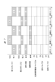
- FIG. 7 is a time chart showing an example of a driving mode of the pump for supplying liquid to the applicator 13 by the liquid supply device 10.
- three application modes 1, 2, and 3 and two circulation modes 1 and 2 are shown.
- the liquid discharge operation from the pump unit 20 to the filter 14 includes a first discharge pattern based on the discharge operation of the first pump 21 and a second discharge pattern based on the discharge operation of the second pump 22.
- first discharge pattern liquid is supplied to the pump chamber 22a of the second pump 22. This discharge operation is common to both application mode and circulation mode.
- liquid is continuously supplied to the applicator 13 via the filter 14 by the second discharge pattern by the pump 22.
- the circulation mode 1 after the application mode 1 ends, the application mode 1 ends with the second ejection pattern, so in the circulation mode 1, the circulation mode 1 is executed using the first ejection pattern.
- circulation mode 2 is performed subsequent to circulation mode 1, the ejection pattern is switched to the second ejection pattern.
- coating mode 3 is performed after circulation mode 2, the coating pattern is switched to the first coating pattern. In this way, in the circulation mode, one of the first pump 21 and the second pump 22 performs the discharge operation, and the liquid of the return flow rate is continuously caused to flow into the return flow path 15.
- the coating mode 3 is further performed following the coating mode 2, since the liquid was applied by the second discharge pattern in the coating mode 2, the liquid is applied to the applicator 13 by the first discharge pattern as shown in FIG. Supplied.
- the application mode is repeated multiple times, the first discharge pattern and the second discharge pattern are alternately performed.
- the circulation mode 2 is performed next to the application mode 3 in the first discharge pattern, it is switched to the second discharge pattern.
- the coating mode a predetermined amount of liquid is discharged onto the object to be coated from either the first pump 21 or the second pump 22.
- the circulation mode one of the first pump 21 and the second pump 22 causes the liquid to flow continuously into the return channel 15 .
- the first pump 21 and the second pump 2 alternately return the liquid and continuously flow the liquid into the channel. Further, it is also possible to switch to the circulation mode after repeating the coating mode a plurality of times, and it is also possible to perform the circulation mode once or multiple times after executing the coating mode once.
- the times in the application mode and circulation mode shown in FIG. 7 are the time during which the plunger 35 moves by a stroke S1, and the time during which the plunger 36 moves by a stroke S2, and are the same time.
- the circulation mode is repeated twice, but it may be repeated three or more times, or the application mode and circulation mode may be switched every time.
- FIG. 8 is a schematic diagram showing a liquid supply device 10 according to another embodiment.
- This liquid supply device 10 is not provided with the application valve 24 and the circulation valve 25 shown in FIG.
- a three-way valve 26 is provided at the connection between the return channel 15 and the liquid supply channel 12. It constitutes a switching means for switching to one of the circulation modes.
- the filter 14 may be arranged in the return channel 15.
- FIG. 9 is a sectional view showing the main parts of a pump unit 20 that is a modified example.
- the cross-sectional area of the first cylinder hole 32 formed in the pump block 31 in FIG. 9 is set to be twice the cross-sectional area of the second cylinder hole 33. Therefore, by making the reciprocating stroke S1 of the plunger 35 and the reciprocating stroke S2 of the plunger 36 the same, the amount of liquid discharged from the pump chamber 21a by the plunger 35 is equal to that of the pump unit 20 shown in FIGS. 2 and 3. Similarly, the amount of liquid discharged from the pump chamber 22a is set by the plunger 36 to be twice the amount of liquid discharged from the pump chamber 22a.
- the liquid supply device 10 equipped with the pump unit 20 shown in FIG. 9 can also operate in a coating mode and a circulation mode, as shown in FIG.
- FIG. 10 is a sectional view showing a pump unit 20 that is another modification.
- the suction side port block 71 is attached to the lower end surface 31c, which is the opening surface of the pump block 31, and the discharge side port block 72 is attached to the upper end surface 31d, which is the opening surface of the pump block 31.
- the port block 71 has a discharge passage 73 communicating with the suction passage 39 and a suction passage 74 communicating with the suction port 71a, and similarly to the liquid supply device 10 shown in FIG.
- the suction side portion 12a of the suction side portion 12a is connected to the suction port 71a.
- a suction side electromagnetic valve 61 a serving as the suction side valve 61 is attached to the port block 71 .
- the suction side electromagnetic valve 61a has the same structure as the passage opening/closing electromagnetic valve 23a, and the suction passage 74 communicates with the inflow hole of the suction side electromagnetic valve 61a, and the discharge passage 73 communicates with the outflow hole.
- the suction-side electromagnetic valve 61a has an open state in which the suction flow path 74 and the discharge flow path 73 communicate with each other and the first suction flow path 39 and the suction port 71a, and a closed state in which communication is interrupted. It is operated by a drive signal applied from the outside.
- the discharge side port block 72 has a suction passage 75 communicating with the discharge passage 43 and a discharge passage 76 communicating with the discharge port 72a, and is similar to the pump unit 20 shown in FIGS. 2 and 3.
- the discharge side portion 12b of the liquid supply path 12 is connected to the discharge port 72a.
- a discharge side electromagnetic valve 65a serving as the discharge side valve 65 is attached to the port block 72.
- the discharge side solenoid valve 65a has the same structure as the passage opening/closing solenoid valve 23a and the suction side solenoid valve 61a, and communicates between the suction passage 75 and the discharge passage 76, and connects the second discharge passage 43 and the discharge passage. It is operated by a drive signal applied from the outside in an open state in which it communicates with the port 72a and in a closed state in which communication is cut off.
- the suction side solenoid valve 61a and the discharge side solenoid valve 65a are solenoid valves that switch between an open state and a closed state based on an external control signal.
- the suction side valve 61 and the discharge side valve 65 are check valves that prevent backflow.
- one of the suction side valve 61 and the discharge side valve 65 may be an electromagnetic valve, and the other may be a check valve.
- FIG. 11 is a time chart showing an example of the driving mode of the pump unit 20, which includes the suction side electromagnetic valve 61a and the discharge side electromagnetic valve 65a, as shown in FIG.
- the suction side electromagnetic valve 61a in both the coating mode and the circulation mode, the suction side electromagnetic valve 61a is turned OFF during the first discharge pattern in which liquid is discharged toward the filter 14 by the discharge operation of the first pump 21. is set to On the other hand, in the second discharge pattern in which liquid is discharged toward the filter 14 by the discharge operation of the second pump 22, the suction side electromagnetic valve 61a is set to ON.
- FIG. 12 is a sectional view showing a modification of the pump that forms the pump unit 20.
- FIG. 12 shows a tube flamm pump 81, and the tube flamm pump 81 can be used in place of the first pump 21 and second pump 22, which are piston pumps described above.
- the discharge capacities are different from each other such that the discharge volume of the tube phragm pump 81 constituting the first pump 21 is twice the discharge volume of the tube phram pump 81 constituting the second pump 22.
- the tube flamm pump 81 includes a cylindrical storage container 82 as a storage member, an inflow side joint member 83 provided at one end of the container, and an outflow side joint member 84 provided at the other end. There is.
- the suction side portion 12a of the liquid supply path 12 is connected to the inflow side joint member 83, and the discharge side portion 12b is connected to the outflow side joint member 84.
- a flexible tube, that is, a tube flammable 85, is provided in the container 82, and the tube flammable 85 has an inflow-side fixed end 85a fixed to the inflow-side joint member 83, and an outflow-side joint member 84.
- the joint members 83 and 84 and the tube flamm 85 are each made of synthetic resin such as fluororesin.
- the tube flamm 85 is partitioned into a pump chamber 86 on the inside and a liquid storage chamber 87 on the outside, and the liquid storage chamber 87 is formed between the tube flamm 85 and the storage container 82 .
- the liquid storage chamber 87 is filled with an incompressible liquid as a liquid medium M, and the liquid medium M is supplied from the outside to the liquid storage chamber 87 through a supply/discharge port 88 formed in the storage container 82.
- a supply/discharge pump 89 is connected to the supply/discharge port 88 .
- This supply/discharge pump 89 has a bellows 92 attached to a rod 91 that reciprocates linearly, and the rod 91 is driven in the axial direction by a driving member such as an electric motor or a pneumatic cylinder.
- a liquid storage chamber 93 outside the bellows 92 is also filled with a liquid medium, and the liquid medium M communicates the liquid storage chamber 93 with the liquid storage chamber 87 of the tube flamm pump 81 .
- the elastic deformation portion 85c of the tube flammable 85 is deformed in the radial direction by the liquid medium in the liquid storage chamber 87.
- the pump chamber 86 contracts.
- the elastic deformation portion 85c expands in the radial direction, and the pump chamber 86 expands.
- a check valve 94 is provided on the suction side 12a of the liquid supply path 12, and a check valve 95 is provided on the discharge side 12b.
- the pump chamber 86 contracts, the liquid L flows out from the pump chamber 86 toward the discharge side portion 12b. At this time, backflow of liquid to the suction side portion 12a is prevented. It is also possible to incorporate the check valve 94 into the joint member 83 and the check valve 95 into the joint member 84. Further, the liquid medium M may be supplied to and discharged from the liquid storage chamber 87 by the rod 91 without providing the bellows 92 in the supply and discharge pump 89.
- the liquid supply device 10 can be driven as shown in FIGS. 7 and 11.
- FIG. 13 is a schematic diagram showing a liquid supply device according to still another embodiment.
- the filter 14 is arranged in the return channel 15, as described above.
- each pump may be not only a piston pump, a tube flamm pump, but also a bellows pump.
- the filter 14 When the filter 14 is disposed in the return flow path 15, the filter 14 may be provided downstream of the circulation valve 25 or upstream thereof.
- the times in the coating mode and the circulation mode are the same, the times in the coating mode and the circulation mode may be different depending on the flow rate suitable for coating or the flow rate suitable for circulation.
- This liquid supply device is applied to supply a liquid to an object to be coated, such as when applying a chemical liquid such as a photoresist liquid to a semiconductor wafer.
Landscapes
- Engineering & Computer Science (AREA)
- Mechanical Engineering (AREA)
- General Engineering & Computer Science (AREA)
- Coating Apparatus (AREA)
- Nozzles (AREA)
Abstract
液体タンク11に収容された液体を塗布具13に供給する液体供給装置10は、液体供給路12に設けられた第1のポンプ21と第2のポンプ22とを有し、塗布具13に向けて流れる液体はフィルタ14により濾過される。フィルタ14を通過した液体を液体タンク11に戻す戻し流路15が設けられ、第1のポンプ21と第2のポンプ22の間には、流路開閉バルブ23が設けられ、塗布具13に液体を供給し戻し流路15への液体の供給を停止する塗布モードと戻し流路15に液体を供給し塗布具13への液体の供給を停止する循環モードのいずれかに切り換えられる。
Description
本発明は、薬液等の液体を被塗布物に供給するための液体供給装置に関する。
液体容器に収容された液体を被供給物に供給するための液体供給装置は、ポンプを有している。特許文献1および特許文献2に記載された薬液供給装置は、径方向に膨張収縮自在の可撓性チューブであるチューブフラムからなるポンプを備えている。液体容器に収容されたフォトレジスト液やポリイミド液等の薬液は、フィルタを通過してポンプにより被塗布物の半導体ウエハの表面に供給される。
液体供給装置に適用されるポンプとしては、チューブフラムポンプのみならず、軸方向に伸縮自在の可撓性のベローズを備えたベローズポンプ、およびピストンがシリンダに往復動自在に装着されたピストンポンプ等がある。小型のピストンポンプはシリンジポンプとも言われる。
特許文献1に記載された薬液供給装置は、単一のポンプから吐出された液体を液体供給路の上流側や液体容器に戻すための戻し流路を有しており、塗布具から液体が塗布されていないときには、戻し流路を介して液体を上流部に戻すことができる。これにより、液体はフィルタを複数回通過して濾過されるので、液体に含まれている微小粒子つまりパーティクルや気泡等の異物をフィルタにより除去し、被塗布物に塗布される液体に含まれる異物を低減することができる。
単一のポンプを備えた薬液供給装置において、液体の循環回数を増加させるには、限られた時間内での液体の流量を増加させる必要がある。しかしながら、ポンプは、被塗布物への塗布量ないし塗布動作に最適化された構造となっており、このタイプのポンプの流量を増加させるには限界がある。
本発明の目的は、フィルタが設けられた液体供給路内を循環する液体量を増加させ、液体に含まれる異物の低減量を高めることにある。
本発明の液体供給装置は、被塗布物に液体を塗布する塗布具に、液体収容部に収容された液体を供給する液体供給装置であって、前記液体収容部に収容された液体を前記塗布具に供給する液体供給路にそれぞれ設けられる第1のポンプおよび第2のポンプと、前記塗布具に向けて流れる液体を濾過するフィルタと、前記フィルタを通過した液体を前記液体収容部に戻す戻し流路と、前記第1のポンプと前記第2のポンプの間に設けられ、前記第1のポンプと前記第2のポンプとの連通を遮断する閉状態と、連通させる開状態とのいずれかに切り換える流路開閉バルブと、前記塗布具に液体を供給し前記戻し流路への液体の供給を停止する塗布モードおよび前記戻し流路に液体を供給し前記塗布具への液体の供給を停止する循環モードのいずれかに切り換える制御部と、を有し、前記塗布モードにおいて、前記第1のポンプと前記第2のポンプの一方は、被塗布物へ液体を吐出し、前記循環モードにおいて、前記第1のポンプと前記第2のポンプの一方は、前記戻し流路へ液体を吐出し、前記第1のポンプと前記第2のポンプは連続的に液体を吐出する。
循環モードにおいては戻し流路に液体が連続的に循環し、戻し流路により液体収容部に向けて戻された液体が液体供給路に供給されるので、液体はフィルタを複数回通過し、液体に含まれる異物を低減させることができる。第1と第2のポンプを備えているので、循環モードにおいて液体を常に循環させるとともに、塗布モードにおいて吐出量を高精度に制御できる。
以下、本発明の実施の形態を図面に基づいて詳細に説明する。それぞれの図面においては、共通性を有する部材には同一の符号が付されている。
図1に示す液体供給装置10は、液体収容部としての液体タンク11に収容されたフォトレジスト液等の液体Lを、半導体ウエハ等の被塗布物に塗布するために使用される。液体供給装置10は、配管やホース等からなる液体供給路12を有し、液体供給路12の先端にはノズル等の塗布具13が設けられており、液体供給路12の基端部は液体タンク11に接続されている。
ポンプユニット20が液体供給路12に設けられており、ポンプユニット20は2台のポンプ21、22を有し、2台のポンプ21、22は液体供給路12に直列となって設けられている。液体供給路12の上流側に設置されるポンプ21を第1のポンプとし、下流側に設置されるポンプ22を第2のポンプとする。両方のポンプ21、22により液体タンク11内の液体は塗布具13に供給される。流路開閉バルブ23が第1のポンプ21と第2のポンプ22の間に設けられ、流路開閉バルブ23は第1のポンプ21と第2のポンプとの連通を遮断する閉位置と、連通させる開位置とに切り換えられる。
ポンプ22から吐出された液体を濾過するためのフィルタ14がポンプ22よりも下流側に位置させて液体供給路12に設けられている。フィルタ14を通過した液体を液体タンク11に戻すために、戻し流路15が液体供給路12と液体タンク11との間に設けられている。フィルタ14の下流側に位置させて液体供給路12には、戻し流路15と液体供給路12とを接続する接続部16が設けられている。
塗布バルブ24が接続部16と塗布具13との間に設けられており、塗布バルブ24はフィルタ14を介して第2のポンプ22と塗布具13との間の流路を連通させて液体を塗布具13に供給する開状態と、流路の連通を遮断して液体の供給を停止する閉状態とに開閉作動する。
循環バルブ25が戻し流路15に設けられており、循環バルブ25は、戻し流路15を介して液体供給路12と液体タンク11との間の流路を連通させて液体を液体タンク11に戻す開状態と、戻し流路15を遮断する閉状態とに開閉作動する。
塗布バルブ24を開状態つまりON状態とし、循環バルブ25を閉状態つまりOFF状態とすると、第2のポンプ22から吐出してフィルタ14で濾過された液体は、塗布バルブ24を通過して塗布具13に供給される。このように、塗布具13に液体を供給し戻し流路15への液体の供給を停止することを塗布モードと定義する。一方、塗布バルブ24を閉状態つまりOFF状態とし、循環バルブ25を開状態つまりON状態とすると、フィルタ14で濾過された液体は、戻し流路15を流れて液体タンク11に戻される。このように、戻し流路15に液体を供給し塗布具13への液体の供給を停止することを循環モードと定義する。
液体供給装置10は、塗布モードと循環モードとのいずれかで作動することができるので、塗布具13から液体が塗布されていないときには、戻し流路15を介して液体を液体タンク11に戻すことができる。これにより、液体はフィルタ14を複数回通過して濾過されるので、液体に含まれている微小粒子、パーティクル、気泡等の異物がフィルタ14により除去され、液体に含まれる異物を低減することができる。なお、図13に示すようにフィルタ14を戻し流路15の接続部16と循環バルブ25の間に配置してもよい。その場合、フィルタ14の影響を受けることがないので、より高い吐出精度で異物が低減された液体を塗布することができる。フィルタ14を戻し流路15に配置する場合は、一定時間循環モードで作動させた後、塗布モードで作動させるようにすると、異物を低減した液体を塗布具13に供給することができて好ましい。
図2は液体供給装置10を構成するポンプユニット20の一例を示す一部切欠き側面図である。図3は図2の要部を示す拡大断面図であり、図4は図3におけるA-A線断面図である。
ポンプユニット20は、直方体形状のポンプブロック31を有している。ポンプブロック31は6つの面を有しており、図2および図3において左側の面を正面31aとし、反対側面を背面31bとし、下側の面を下端面31cとし、上側の面を上端面31dとする。図4において左右の面を側面31e、31fとする。正面31aと背面31bは平行であり、下端面31cと上端面31dは平行であるとともに正面31aと背面31bに対して直角である。
底付きの第1のシリンダ孔32が背面31bに開口してポンプブロック31に設けられ、底付きの第2のシリンダ孔33が背面31bに開口してポンプブロック31に設けられている。両方のシリンダ孔32、33は相互に平行である。このように、ポンプブロック31は、2つのシリンダ孔32、33が単一のブロック部材に一体形成された一体型である。正面31aおよび上下の端面31c、31dは外部に露出した外面である。
ポンプブロック31の背面31bは駆動機構取付面であり、ポンプ駆動機構34が背面31bに装着される。ポンプ駆動機構34は第1のポンプ21と第2のポンプ22とを駆動する。ポンプ21はポンプ部材としてのプランジャ35を有し、ポンプ22はポンプ部材としてのプランジャ36を有している。
プランジャ35はシリンダ孔32に往復動自在に装着される。第1のポンプ室21aがシリンダ孔32とプランジャ35により形成され、ポンプ室21aはプランジャ35の往復動により膨張収縮される。プランジャ35の収縮限位置は、プランジャ35が第1のシリンダ孔32の底面に最接近した位置により設定される。プランジャ36はシリンダ孔33に往復動自在に装着される。第2のポンプ室22aがシリンダ孔33とプランジャ36により形成され、ポンプ室22aはプランジャ36の往復動により膨張収縮される。プランジャ36の収縮限位置は、プランジャ36がシリンダ孔33の底面に最接近した位置により設定される。図2および図3においては、プランジャ36がシリンダ孔33の底面に最接近した状態を示す。
プランジャ35とシリンダ孔32の間には僅かな隙間が設けられており、ポンプ室21aからの液体の漏出はシール部材37により防止される。同様に、ポンプ室22aからの液体の漏出はシール部材38により防止される。
第1の吸入流路39がポンプブロック31に形成され、吸入流路39は開口面である下端面31cに開口し、ポンプ室21aに連通する。第1の吐出流路41がポンプブロック31に形成され、吐出流路41は弁取付面である正面31aに開口し、ポンプ室21aに連通する。吐出流路41は、第1の連通部である連通部41aと吐出部41bとを備える。連通部41aは、ポンプ室21aに連通し、吸入流路39に同軸状であって、シリンダ孔32に垂直である。吐出部41bは、シリンダ孔32と平行であり、正面31aに開口している。
第2の吸入流路42がポンプブロック31に形成され、吸入流路42は取付面である正面31aに開口し、ポンプ室22aに連通する。第2の吐出流路43がポンプブロック31に形成され、吐出流路43は開口面である上端面31dに開口し、ポンプ室22aに連通する。吸入流路42は、第2の連通部である連通部42aと吸入部42bとを備える。連通部42aは、ポンプ室22aに連通し、吐出流路43と同軸状であり、シリンダ孔33に垂直である。吸入部42bは、シリンダ孔33と平行であり、吐出部41bと平行となって正面31aに開口している。
ポンプ駆動機構34は、ポンプ部材としてのプランジャ35を往復動するための第1のモータ44と、ポンプ部材としてのプランジャ36を往復動するための第2のモータ45とを備えている。プランジャ35にねじ結合されるナットがポンプ駆動機構34の内部に組み込まれており、モータ44の主軸の回転運動は、ナットを介してプランジャ35の直線往復運動に変換される。同様に、モータ45の主軸の回転運動は、プランジャ36の直線往復運動に変換される。
プランジャ35がポンプ室21aを膨張させる方向に駆動されてポンプ21が吸入動作を行うときには、吸入流路39からポンプ室21aに液体が吸入される。一方、プランジャ36がポンプ室22aを収縮させる方向駆動されてポンプ22が吐出動作を行うときには、ポンプ室22aから吐出流路43に液体が吐出される。
図1に示した流路開閉バルブ23としての流路開閉電磁バルブ23aが弁取付面としての正面31aに取り付けられている。流路開閉電磁バルブ23aは、ポンプ21が吸入動作し、ポンプ22が吐出動作するときに、吐出流路41と吸入流路42との連通を遮断する。さらに、流路開閉電磁バルブ23aは、ポンプ22が吸入動作し、ポンプ21が吐出動作するときに、吐出流路41と吸入流路42とを連通させる。このときには、ポンプ21の吐出動作により、ポンプ室22aに液体が供給されるとともに、フィルタ14に向けてポンプ室22aから液体が吐出される。つまり、ポンプ21が吐出動作を行うとともに、ポンプ22が吸入動作を行うときには、流路開閉電磁バルブ23aを介してポンプ室21aからポンプ室22aに液体が供給される。
このように、流路開閉電磁バルブ23aは、ポンプブロック31の外側に設けられ、吐出流路41と吸入流路42とを連通させる開状態と、連通を遮断する閉状態とに動作する。それぞれのポンプ21、22が吐出動作を行うときのモータ44、45の回転方向を正転方向とすると、吸入動作するときにはモータ44、45は逆転方向に駆動される。
図2および図3に示されるポンプブロック31においては、シリンダ孔32の径D1とシリンダ孔33の径D2は同一径(D1=D2)であり、両方のシリンダ孔32、33の横断面積は同一である。また、ポンプ21のプランジャ35の往復動ストロークS1は、ポンプ22のプランジャ36の往復動ストロークS2の2倍(S1=2S2)であり、プランジャ35の往復動時の速度は、プランジャ36の往復動時の速度の2倍に設定されている。これにより、ポンプ22の吐出量と吸入量を単位時間当たりLとすると、ポンプ21の単位時間当たりの吐出量と吸入量は2Lとなる。つまり、ポンプ21の吐出量はポンプ22の吐出量の2倍である。
上述のように、ポンプ21の単位時間当たりの吐出量は、ポンプ22の単位時間当たりの吸入量の2倍であり、流路開閉電磁バルブ23aが開いた状態のもとでは、ポンプ21が吐出動作するとともにポンプ22が吸入動作する。これにより、ポンプ室21a内の液体がポンプ室22aに流入するとともにポンプ室22aからフィルタ14に向けて吐出される。つまり、ポンプ22のプランジャ36が吸入動作し、ポンプ21のプランジャ35が吐出動作するときには、プランジャ35の吐出動作により、ポンプ室21a内の液体は、ポンプ室22aに供給されるとともにポンプ室22aを介して吐出流路43に吐出される。
したがって、ポンプユニット20から液体を吐出する吐出動作には、ポンプ21の吐出動作によりポンプ22を通過させて吐出する吐出パターンと、ポンプ22の吐出動作により吐出する吐出パターンとがある。
吐出流路43に流れる液体は、ポンプブロック31の下端面から上端面に向けて流路内を流れるので、ポンプユニット20に供給される液体に気泡が含まれていても、気泡が流路内に留まることなく、気泡を外部に排出することができる。
図5は図2に示された流路開閉電磁バルブ23aの要部を示す断面図である。流路開閉電磁バルブ23aは、ソレノイドケース46が設けられた弁収容ケース47を有し、ポートプレート48が弁収容ケース47に取り付けられる。流路開閉電磁バルブ23aは、外部からの制御信号に基づいて弁部材49を開閉動作させ開状態と閉状態を切り換える弁駆動部を有している。弁駆動部としての可動鉄心50がソレノイドケース46内に軸方向に往復動自在に装着され、コイルばね51により、ポートプレート48に向けて突出する方向のばね力が可動鉄心50に加えられている。図示しないコイルがソレノイドケース46に組み込まれており、コイルに制御信号としての駆動電流が印加されると、可動鉄心50はばね力に抗して後退する方向に駆動される。ポートプレート48は、図2および図3に示されるように、ねじ部材52によりポンプブロック31の正面31aに取り外し自在に装着される。ねじ部材52が取り付けられるねじ取付孔52aがポートプレート48に形成されている。
図5に示されるように、揺動アーム53が弁収容ケース47内に配置され、揺動アーム53は可動鉄心50の前方を可動鉄心50を横切る方向に延びている。揺動アーム53の基端部は支持軸54により弁収容ケース47に揺動自在に支持される。弁駆動レバー55が揺動アーム53とポートプレート48との間に配置され、弁駆動レバー55は揺動アーム53に沿って延びている。弁駆動レバー55の長手方向中央部は支持軸56により弁収容ケース47内に揺動自在に支持され、弁駆動レバー55は支持軸56を中心に揺動する。
弁部材49はゴム製であり、弁駆動レバー55に設けられており、弁部材49とポートプレート48とにより液体流路57が形成される。流入孔58と流出孔59がポートプレート48に形成され、流入孔58と流出孔59は液体流路57により連通される。流入孔58は第1の吐出流路41に連通され、流出孔59は第2の吸入流路42に連通される。開閉部49aが流出孔59に対応して弁部材49に設けられており、開閉部49aは流出孔59を開閉する。コイルばね60が揺動アーム53の基端部と弁駆動レバー55の一端部との間に配置され、コイルばね60は開閉部49aが流出孔59を開く方向のばね力を弁駆動レバー55に加える。
作動部53aが揺動アーム53の先端部に設けられ、作動部53aは弁駆動レバー55の他端部に接触している。力点部53bが揺動アーム53の長手方向中央部に設けられ、力点部53bは可動鉄心50に向けて突出し、可動鉄心50の先端面が力点部53bに接触している。可動鉄心50は揺動アーム53の長手方向中央部に接触しているので、作動部53aの揺動ストロークは、可動鉄心50の軸方向ストロークよりも拡大され、拡大された作動部53aの揺動ストロークにより、開閉部49aは開閉作動される。したがって、小型の流路開閉電磁バルブ23aにより、液体流路57と流出孔59との連通開度を確保しつつ、開閉部49aは高速で流出孔59を開閉することができる。
図5(A)はコイルばね51のばね力により、開閉部49aが流出孔59を塞いで流入孔58と流出孔59の連通を遮断した状態、つまり閉じた状態を示す。図5(B)はコイルに駆動電流が印加されて可動鉄心50が後退駆動されてコイルばね60のばね力により開閉部49aが流出孔59から離れて流入孔58と流出孔59とを連通させた状態、つまり開いた状態を示す。
流路開閉電磁バルブ23aはポンプブロック31の内部に組み込まれることなく、外部に設けられているので、ねじ部材52を緩めることにより、流路開閉電磁バルブ23aを容易にポンプブロック31から取り外すことができ、流路開閉電磁バルブ23aの点検や交換等のメンテナンス性を向上させることができる。
吸入側バルブ61が第1の開口面としての下端面31cに設けられている。図3に示される吸入側バルブ61は逆止弁である。吸入側バルブ61は、図3に示されるように、下端面31cに取り付けられる弁ケース62を有し、第1の吸入流路39に連通する弁室63が弁ケース62に設けられている。吸入ポート62aが弁ケース62に設けられ、液体タンク11に接続される液体供給路12の吸入側部12aが吸入ポート62aに接続される。ボールからなる弁体64が弁室63に設けられている。吸入側バルブ61は、プランジャ35の吸入動作時に液体タンク11に収容された液体Lをポンプ室21aに案内し、プランジャ35の吐出動作時には弁体64が弁室63を閉じて液体タンク11への液体の逆流を阻止する。
吐出側バルブ65が開口面としての上端面31dに設けられている。図3に示される吐出側バルブ65は吸入側バルブ61と同様に逆止弁である。吐出側バルブ65は、上端面31dに取り付けられる弁ケース66を有し、液体供給路12の吐出側部12bに連通する弁室67が弁ケース66に設けられている。吐出ポート66aが弁ケース66に設けられ、吐出側部12bが吐出ポート66aに接続される。ボールからなる弁体68が弁室67内に設けられている。吐出側バルブ65は、液体供給装置10の停止時に、弁体68が弁室67を閉じて塗布具13からの液ダレを防止する。
図6は、液体供給装置10の制御回路を示すブロック図であり、上述した第1のポンプ21のモータ44、第2のポンプ22のモータ45、流路開閉電磁バルブ23a、塗布バルブ24および循環バルブ25は、制御部70により作動が制御される。制御部70は操作盤69に接続されており、操作盤69に設けられた図示しない指令キーにより液体供給装置10の作動が開始される。制御部70は制御信号を演算するマイクロプロセッサや制御プログラムが格納されるメモリ等を有している。制御部70によってポンプ21、22とバルブ23a、24、25の作動が制御され、液体供給装置10は塗布モードと循環モードに設定される。
図7は、液体供給装置10により塗布具13に液体を供給するためのポンプの駆動形態の一例を示すタイムチャートである。図7においては、3回の塗布モード1、2,3と2回の循環モード1、2を示す。
ポンプユニット20からフィルタ14への液体の吐出動作は、第1のポンプ21の吐出動作による第1吐出パターンと、第2のポンプ22の吐出動作による第2吐出パターンとがある。第1吐出パターンにおいては第2のポンプ22のポンプ室22aに液体が供給される。この吐出動作は塗布モードと循環モードのいずれでも共通である。
図7における塗布モード1においては、ポンプ22による第2吐出パターンによりフィルタ14を介して塗布具13に液体が連続的に供給される。塗布モード1が終了した後の循環モード1においては、塗布モード1が第2吐出パターンで終了したので、循環モード1においては第1吐出パターンにより循環モード1が実行される。循環モード1に引き続いて、さらに循環モード2が行われるときには、第2の吐出パターンに切り換えられる。循環モード2の後に塗布モード3が行われるときは、第1の塗布パターンに切り換えられる。このように、循環モードにおいては、第1のポンプ21と第2のポンプ22の一方が吐出動作を行い、戻し流路15に戻し流量の液体を連続して流す。
塗布モード2に引き続いてさらに塗布モード3が行われるときには、塗布モード2が第2吐出パターンにより液体が塗布されたので、図7に示されるように、第1吐出パターンにより液体が塗布具13に供給される。複数回の塗布モードが繰り返されるときには、第1吐出パターンと第2吐出パターンとが交互に行われる。第1吐出パターンでの塗布モード3の次に循環モード2が行われるときには、第2吐出パターンに切り換えられる。
このように、塗布モードにおいては、第1のポンプ21と第2のポンプ22の一方から被塗布物に所定の塗布量の液体が吐出される。一方、循環モードにおいては、第1のポンプ21と第2のポンプ22の一方が液体を戻し流路15に連続的に流す。循環モードの時間の方が塗布モードの時間より長い場合は、第1のポンプ21と第2のポンプ2が交互に液体を戻し流路に連続的に流す。また、塗布モードを複数回繰り返した後に、循環モードに切り換えることも可能であり、1回の塗布モードが実行された後に循環モード1回または複数回を行うことも可能である。
図7に示した塗布モードと循環モードの時間は、プランジャ35がストロークS1だけ移動する時間であり、プランジャ36がストロークS2だけ移動する時間であり、相互に同一時間である。図7においては、循環モードを2回繰り返しているが、3回以上繰り返してもよいし塗布モードと循環モードを1回ごとに切り換えてもよい。
図8は他の実施の形態である液体供給装置10を示す概略図である。この液体供給装置10においては、図1に示した塗布バルブ24と循環バルブ25が設けられていない。三方弁26が戻し流路15と液体供給路12との接続部に設けられており、三方弁26は、フィルタ14を通過した液体を塗布具13に供給する塗布モードと、液体を液体タンク11に戻す循環モードのいずれかに切り換える切換手段を構成している。なお、図8の液体供給装置10において、フィルタ14は戻し流路15に配置してもよい。
図9は、変形例であるポンプユニット20の要部を示す断面図である。図9のポンプブロック31に形成された第1のシリンダ孔32の断面積は、第2のシリンダ孔33の断面積の2倍に設定されている。したがって、プランジャ35の往復動ストロークS1とプランジャ36の往復動ストロークS2を同一とすることにより、プランジャ35によるポンプ室21aからの液体の吐出量は、図2および図3に示したポンプユニット20と同様に、プランジャ36によりポンプ室22aからの液体の吐出量の2倍に設定される。図9に示すポンプユニット20を備えた液体供給装置10においても、図7に示すように、塗布モードと循環モードとを行うことができる。
図10は、他の変形例であるポンプユニット20を示す断面図である。吸入側のポートブロック71がポンプブロック31の開口面である下端面31c取り付けられ、吐出側のポートブロック72がポンプブロック31の開口面である上端面31dに取り付けられる。
ポートブロック71は、吸入流路39に連通される吐出流路73と、吸入ポート71aに連通する吸入流路74とを有し、図1に示した液体供給装置10と同様に、液体供給路の吸入側部12aが吸入ポート71aに接続される。吸入側バルブ61としての吸入側電磁バルブ61aがポートブロック71に取り付けられる。吸入側電磁バルブ61aは、流路開閉電磁バルブ23aと同様の構造であり、吸入流路74は吸入側電磁バルブ61aの流入孔に連通され、吐出流路73は流出孔に連通される。吸入側電磁バルブ61aは、吸入流路74と吐出流路73とを連通させて、第1の吸入流路39と吸入ポート71aとを連通させる開いた状態と、連通を遮断する閉じた状態とに、外部から印加される駆動信号により作動する。
吐出側のポートブロック72は、吐出流路43に連通される吸入流路75と、吐出ポート72aに連通する吐出流路76とを有し、図2および図3に示したポンプユニット20と同様に、液体供給路12の吐出側部12bが吐出ポート72aに接続される。吐出側バルブ65としての吐出側電磁バルブ65aがポートブロック72に取り付けられる。吐出側電磁バルブ65aは、流路開閉電磁バルブ23aおよび吸入側電磁バルブ61aと同様の構造であり、吸入流路75と吐出流路76とを連通させて、第2の吐出流路43と吐出ポート72aとを連通させる開いた状態と、連通を遮断する閉じた状態とに、外部から印加される駆動信号により作動する。
図10に示されるように、流路開閉電磁バルブ23aと吸入側電磁バルブ61aと吐出側電磁バルブ65aがポンプブロック31の正面31a側に配置されると、それぞれの電磁バルブの交換等のメンテナンスを容易に行うことができる。
図10に示されるポンプユニット20においては、吸入側電磁バルブ61aと吐出側電磁バルブ65aが外部からの制御信号に基づいて開状態と閉状態とを切り換える電磁バルブであり、図2および図3に示したポンプユニット20においては、吸入側バルブ61と吐出側バルブ65が逆流を阻止する逆止弁である。これに対し、それぞれのポンプユニット20において、吸入側バルブ61と吐出側バルブ65の一方を、電磁バルブとし、他方を逆止弁としても良い。
図11は、図10に示すように吸入側電磁バルブ61aと吐出側電磁バルブ65aとを備えたポンプユニット20の駆動形態の一例を示すタイムチャートである。
図11に示す場合には、塗布モードと循環モードのいずれにおいても、第1のポンプ21の吐出動作によりフィルタ14に向けて液体を吐出する第1吐出パターンのときには、吸入側電磁バルブ61aはOFFに設定される。一方、フィルタ14に向けて第2のポンプ22の吐出動作により液体を吐出する第2吐出パターンのときには、吸入側電磁バルブ61aはONに設定される。
図11における循環モードにおいては、図7に示した循環モードと同様に、第1のポンプ21と第2のポンプ22の一方が戻し流路15に戻し流量の液体を吐出する。
図12はポンプユニット20を成形するポンプの変形例を示す断面図である。図12はチューブフラムポンプ81を示しており、上述したピストンポンプである第1のポンプ21と第2のポンプ22に代えて、チューブフラムポンプ81を使用することができる。ただし、第1のポンプ21を構成するチューブフラムポンプ81の吐出量が第2のポンプ22を構成するチューブフラムポンプ81の吐出量の2倍となるように、吐出容量は相互に相違する。
チューブフラムポンプ81は、収容部材としての円筒形状の収容容器82と、これの一端部に設けられる流入側の継手部材83と、他端部に設けられる流出側の継手部材84とを有している。流入側の継手部材83には液体供給路12の吸入側部12aが接続され、流出側の継手部材84には吐出側部12bが接続される。可撓性のチューブつまりチューブフラム85が収容容器82内に設けられており、チューブフラム85は、流入側の継手部材83に固定される流入側の固定端部85aと、流出側の継手部材84に固定される流出側の固定端部85bと、両方の固定端部85a、85bの間の弾性変形部85cとを有している。継手部材83,84とチューブフラム85は、それぞれフッ素樹脂等の合成樹脂により形成されている。
チューブフラム85によりその内側のポンプ室86と、外側の液体収容室87とに仕切られており、液体収容室87はチューブフラム85と収容容器82との間に形成されている。液体収容室87には非圧縮性である液体が液媒体Mとして充填されており、収容容器82に形成された給排ポート88を介して外部から液体収容室87に液媒体Mが供給される。給排ポンプ89が給排ポート88に接続されている。この給排ポンプ89は直線往復動するロッド91に取り付けられたベローズ92を有しており、ロッド91は電動モータや空気圧シリンダ等の駆動部材により軸方向に駆動される。ベローズ92の外側の液体収容室93にも液媒体が充填されており、液媒体Mにより液体収容室93はチューブフラムポンプ81の液体収容室87に連通している。
給排ポンプ89を駆動することにより、液体収容室93から液体収容室87に向けて液媒体Mが供給されると、液体収容室87の液媒体によりチューブフラム85の弾性変形部85cは径方向に収縮しポンプ室86が収縮する。一方、液体収容室87から液媒体Mが排出されると、弾性変形部85cは径方向に膨張し、ポンプ室86が膨張する。逆止弁94が液体供給路12の吸入側部12aに設けられ、逆止弁95が吐出側部12bに設けられており、ポンプ室86が膨張すると、吸入側部12aから液体Lがポンプ室86に流入する。このときには、吐出側部12bからの液体の逆流が阻止される。一方、ポンプ室86が収縮すると、ポンプ室86から吐出側部12bに向けて液体Lが流出する。このときには、吸入側部12aへの液体の逆流が阻止される。逆止弁94を継手部材83に組み込み、逆止弁95を継手部材84に組み込むこともできる。また、給排ポンプ89にベローズ92を設けることなく、ロッド91によって液媒体Mを、液体収容室87に給排してもよい。
第1のポンプ21および第2のポンプ22としてチューブフラムポンプ81を使用した場合においても、図7および図11に示すようにして液体供給装置10を駆動することができる。
図13はさらに他の実施の形態である液体供給装置を示す概略図である。この液体供給装置10においては、前述のように、フィルタ14が戻し流路15に配置されている。
本発明は前記実施の形態に限定されるものではなく、その要旨を逸脱しない範囲で種々変更可能である。例えば、それぞれのポンプの形態としては、ピストンポンプ、チューブフラムポンプのみならず、ベローズポンプとしてもよい。戻し流路15にフィルタ14を配置する場合、フィルタ14は循環バルブ25の下流に設けてもよいし、上流に設けてもよい。また、塗布モードと循環モードの時間は同じとしているが、塗布に適した流量や循環に適した流量に合わせて塗布モードと循環モードの時間を相違させてもよい。
この液体供給装置は、半導体ウエハにフォトレジスト液等の薬液を塗布する場合のように、被塗布物に液体を供給するために適用される。
Claims (11)
- 被塗布物に液体を塗布する塗布具に、液体収容部に収容された液体を供給する液体供給装置であって、
前記液体収容部に収容された液体を前記塗布具に供給する液体供給路にそれぞれ設けられる第1のポンプおよび第2のポンプと、
前記塗布具に向けて流れる液体を濾過するフィルタと、
前記フィルタを通過した液体を前記液体収容部に戻す戻し流路と、
前記第1のポンプと前記第2のポンプの間に設けられ、前記第1のポンプと前記第2のポンプとの連通を遮断する閉状態と、連通させる開状態とのいずれかに切り換える流路開閉バルブと、
前記塗布具に液体を供給し前記戻し流路への液体の供給を停止する塗布モードと、前記戻し流路に液体を供給し前記塗布具への液体の供給を停止する循環モードとのいずれかに切り換える制御部と、
を有し、
前記塗布モードにおいて、前記第1のポンプと前記第2のポンプの一方は、被塗布物へ液体を吐出し、
前記循環モードにおいて、前記第1のポンプと前記第2のポンプの一方は、前記戻し流路へ液体を吐出することにより戻し流量の液体を連続して流す、液体供給装置。 - 請求項1記載の液体供給装置において、
前記第1のポンプと前記第2のポンプは直列に接続され、下流側のポンプと前記塗布具との間に前記フィルタが配置され、前記塗布具と前記フィルタの間に前記戻し流路と前記液体供給路を接続する接続部が設けられる、液体供給装置。 - 請求項1記載の液体供給装置において、
前記第1のポンプと前記第2のポンプは直列に接続され、前記戻し流路に前記フィルタが配置され、下流側のポンプと前記塗布具との間に前記戻し流路と前記液体供給路を接続する接続部が設けられる、液体供給装置。 - 請求項2または3に記載の液体供給装置において、
前記接続部と前記塗布具の間に設けられる塗布バルブと、
前記戻し流路に設けられる循環バルブと、を有し、
前記循環モードでは、前記塗布バルブを閉じるとともに前記循環バルブを開き、
前記塗布モードでは、前記塗布バルブを開くとともに前記循環バルブを閉じる、液体供給装置。 - 請求項2または3に記載の液体供給装置において、
前記接続部に、前記塗布モードと前記循環モードを切り換える切換手段を設ける、液体供給装置。 - 請求項1~5のいずれか1項に記載の液体供給装置において、
前記第1のポンプは、第1の吸入流路と第1の吐出流路および前記第1の吸入流路と前記第1の吐出流路に連通する第1のポンプ室とが設けられ、
前記第2のポンプは、第2の吸入流路と第2の吐出流路および前記第2の吸入流路と前記第2の吐出流路に連通する第2のポンプ室とが設けられ、
前記第1の吸入流路から前記第1のポンプ室に液体を吸入する吸入動作および前記第2の吐出流路に前記第2のポンプ室から液体を吐出する吐出動作するときに、前記流路開閉バルブは前記第1の吐出流路と前記第2の吸入流路との連通を遮断し、
前記第2の吸入流路から第2のポンプ室に液体を吸入する吸入動作および前記第1の吐出流路に前記第1のポンプ室から液体を吐出する吐出動作するときに、前記流路開閉バルブは前記第1の吐出流路と前記第2の吸入流路とを連通させる、液体供給装置。 - 請求項1~6のいずれか1項に記載の液体供給装置において、
前記第1のポンプと前記第2のポンプは、ポンプブロックに一体形成され、
前記流路開閉バルブは、前記ポンプブロックの外側に設けられる、液体供給装置。 - 請求項1~7のいずれか1項に記載の液体供給装置において、前記流路開閉バルブは、逆止弁である、液体供給装置。
- 請求項1~7のいずれか1項に記載の液体供給装置において、前記流路開閉バルブは、外部の制御信号に基づいて、開状態と閉状態とを切り換える電磁バルブである、液体供給装置。
- 請求項1~9のいずれか1項に記載の液体供給装置において、前記第1のポンプの吐出量は、前記第2のポンプの吐出量の2倍である、液体供給装置。
- 請求項1~10のいずれか1項に記載の液体供給装置において、前記循環モードにおいて、前記第1のポンプと前記第2のポンプは、前記戻し流路へ液体を交互に吐出することにより戻し流量の液体を連続して流す、液体供給装置。
Applications Claiming Priority (2)
| Application Number | Priority Date | Filing Date | Title |
|---|---|---|---|
| JP2022056396 | 2022-03-30 | ||
| JP2022-056396 | 2022-03-30 |
Publications (1)
| Publication Number | Publication Date |
|---|---|
| WO2023188488A1 true WO2023188488A1 (ja) | 2023-10-05 |
Family
ID=88200605
Family Applications (1)
| Application Number | Title | Priority Date | Filing Date |
|---|---|---|---|
| PCT/JP2022/039529 WO2023188488A1 (ja) | 2022-03-30 | 2022-10-24 | 液体供給装置 |
Country Status (2)
| Country | Link |
|---|---|
| TW (1) | TW202337568A (ja) |
| WO (1) | WO2023188488A1 (ja) |
Citations (5)
| Publication number | Priority date | Publication date | Assignee | Title |
|---|---|---|---|---|
| JP2000120530A (ja) * | 1998-10-13 | 2000-04-25 | Koganei Corp | 薬液供給方法および薬液供給装置 |
| JP2008018310A (ja) * | 2006-07-11 | 2008-01-31 | Koganei Corp | 薬液供給装置および薬液供給方法 |
| JP2011101851A (ja) * | 2009-11-11 | 2011-05-26 | Koganei Corp | 薬液供給装置および薬液供給方法 |
| JP2014001663A (ja) * | 2012-06-18 | 2014-01-09 | Koganei Corp | 液体供給装置 |
| JP2020002881A (ja) * | 2018-06-28 | 2020-01-09 | 株式会社コガネイ | 液体供給装置および液体供給方法 |
-
2022
- 2022-10-24 WO PCT/JP2022/039529 patent/WO2023188488A1/ja unknown
- 2022-11-01 TW TW111141506A patent/TW202337568A/zh unknown
Patent Citations (5)
| Publication number | Priority date | Publication date | Assignee | Title |
|---|---|---|---|---|
| JP2000120530A (ja) * | 1998-10-13 | 2000-04-25 | Koganei Corp | 薬液供給方法および薬液供給装置 |
| JP2008018310A (ja) * | 2006-07-11 | 2008-01-31 | Koganei Corp | 薬液供給装置および薬液供給方法 |
| JP2011101851A (ja) * | 2009-11-11 | 2011-05-26 | Koganei Corp | 薬液供給装置および薬液供給方法 |
| JP2014001663A (ja) * | 2012-06-18 | 2014-01-09 | Koganei Corp | 液体供給装置 |
| JP2020002881A (ja) * | 2018-06-28 | 2020-01-09 | 株式会社コガネイ | 液体供給装置および液体供給方法 |
Also Published As
| Publication number | Publication date |
|---|---|
| TW202337568A (zh) | 2023-10-01 |
Similar Documents
| Publication | Publication Date | Title |
|---|---|---|
| KR102591031B1 (ko) | 액체공급장치 및 액체공급방법 | |
| JP4566955B2 (ja) | 薬液供給装置および薬液供給方法 | |
| WO2011058792A1 (ja) | 薬液供給装置および薬液供給方法 | |
| JP4422040B2 (ja) | 弁装置 | |
| KR860000976B1 (ko) | 왕복 펌프 | |
| KR101630004B1 (ko) | 다이어프램 밸브 | |
| KR101391070B1 (ko) | 약액 공급 장치 | |
| US5807085A (en) | Liquid medicine supplying system with valve devices | |
| JP5114527B2 (ja) | 液体供給装置 | |
| WO2009012083A2 (en) | Precision pump with multiple heads | |
| WO2023188488A1 (ja) | 液体供給装置 | |
| WO2005089955A1 (ja) | 薬液供給装置 | |
| JP3619616B2 (ja) | 薬液供給装置の駆動方法 | |
| US20220331833A1 (en) | Liquid Supplying Device | |
| JP3568866B2 (ja) | 往復動型ポンプ | |
| JP4566989B2 (ja) | 薬液供給装置 | |
| JP4701257B2 (ja) | 液体ポンプシステム | |
| JP2008157027A (ja) | 電磁ポンプ | |
| JPH10308347A (ja) | 基板への処理液供給装置 | |
| JP2017031881A (ja) | 液体供給装置 | |
| JPH11182417A (ja) | プランジャポンプ駆動装置 | |
| JP4610582B2 (ja) | 液体ポンプシステム | |
| JP4756008B2 (ja) | 液体ポンプ装置の駆動方法 | |
| JP2001153034A (ja) | 液体吐出ポンプ | |
| JP2001041201A (ja) | アクチュエータ、ポンプ装置および液体供給システム |
Legal Events
| Date | Code | Title | Description |
|---|---|---|---|
| 121 | Ep: the epo has been informed by wipo that ep was designated in this application |
Ref document number: 22935619 Country of ref document: EP Kind code of ref document: A1 |