WO2023149134A1 - 工作機械 - Google Patents
工作機械 Download PDFInfo
- Publication number
- WO2023149134A1 WO2023149134A1 PCT/JP2022/047803 JP2022047803W WO2023149134A1 WO 2023149134 A1 WO2023149134 A1 WO 2023149134A1 JP 2022047803 W JP2022047803 W JP 2022047803W WO 2023149134 A1 WO2023149134 A1 WO 2023149134A1
- Authority
- WO
- WIPO (PCT)
- Prior art keywords
- tool
- hand
- tools
- transfer
- schedule
- Prior art date
- Legal status (The legal status is an assumption and is not a legal conclusion. Google has not performed a legal analysis and makes no representation as to the accuracy of the status listed.)
- Ceased
Links
Images


Classifications
-
- B—PERFORMING OPERATIONS; TRANSPORTING
- B23—MACHINE TOOLS; METAL-WORKING NOT OTHERWISE PROVIDED FOR
- B23B—TURNING; BORING
- B23B29/00—Holders for non-rotary cutting tools; Boring bars or boring heads; Accessories for tool holders
- B23B29/24—Tool holders for a plurality of cutting tools, e.g. turrets
-
- B—PERFORMING OPERATIONS; TRANSPORTING
- B23—MACHINE TOOLS; METAL-WORKING NOT OTHERWISE PROVIDED FOR
- B23Q—DETAILS, COMPONENTS, OR ACCESSORIES FOR MACHINE TOOLS, e.g. ARRANGEMENTS FOR COPYING OR CONTROLLING; MACHINE TOOLS IN GENERAL CHARACTERISED BY THE CONSTRUCTION OF PARTICULAR DETAILS OR COMPONENTS; COMBINATIONS OR ASSOCIATIONS OF METAL-WORKING MACHINES, NOT DIRECTED TO A PARTICULAR RESULT
- B23Q3/00—Devices holding, supporting, or positioning work or tools, of a kind normally removable from the machine
- B23Q3/155—Arrangements for automatic insertion or removal of tools, e.g. combined with manual handling
-
- B—PERFORMING OPERATIONS; TRANSPORTING
- B23—MACHINE TOOLS; METAL-WORKING NOT OTHERWISE PROVIDED FOR
- B23Q—DETAILS, COMPONENTS, OR ACCESSORIES FOR MACHINE TOOLS, e.g. ARRANGEMENTS FOR COPYING OR CONTROLLING; MACHINE TOOLS IN GENERAL CHARACTERISED BY THE CONSTRUCTION OF PARTICULAR DETAILS OR COMPONENTS; COMBINATIONS OR ASSOCIATIONS OF METAL-WORKING MACHINES, NOT DIRECTED TO A PARTICULAR RESULT
- B23Q41/00—Combinations or associations of metal-working machines not directed to a particular result according to classes B21, B23, or B24
-
- Y—GENERAL TAGGING OF NEW TECHNOLOGICAL DEVELOPMENTS; GENERAL TAGGING OF CROSS-SECTIONAL TECHNOLOGIES SPANNING OVER SEVERAL SECTIONS OF THE IPC; TECHNICAL SUBJECTS COVERED BY FORMER USPC CROSS-REFERENCE ART COLLECTIONS [XRACs] AND DIGESTS
- Y02—TECHNOLOGIES OR APPLICATIONS FOR MITIGATION OR ADAPTATION AGAINST CLIMATE CHANGE
- Y02P—CLIMATE CHANGE MITIGATION TECHNOLOGIES IN THE PRODUCTION OR PROCESSING OF GOODS
- Y02P90/00—Enabling technologies with a potential contribution to greenhouse gas [GHG] emissions mitigation
- Y02P90/02—Total factory control, e.g. smart factories, flexible manufacturing systems [FMS] or integrated manufacturing systems [IMS]
Definitions
- the present invention relates to tool changing technology for machine tools.
- Machine tools include devices that cut workpieces into desired shapes and devices that create workpieces by laminating metal powder.
- Machine tools for cutting include a turning center that processes the workpiece by applying a cutting tool to the rotating workpiece, and a machining center that processes the workpiece by applying a rotating tool to the workpiece. These functions are combined. There is a multitasking machine equipped with.
- a machine tool equipped with a turret may have multiple tools attached to it.
- a machine tool processes a workpiece while moving the tool post three-dimensionally according to a machining program prepared in advance and selecting a tool to be applied to the workpiece from among a plurality of tools mounted on the tool post.
- Some machine tools have a tool storage section that stores a large number of tools. When the required tool is not attached to the tool post, the machine tool attaches the designated tool from the tool storage section to the tool post and then continues machining the workpiece.
- the tool attached to the tool rest will be referred to as the "work tool”
- the tool stored in the tool storage section will be referred to as the "reserve tool”. They are simply referred to as "tools” when they are not distinguished from each other (see Patent Documents 1 to 3).
- the turret has multiple areas called stations, holders are attached to the stations, and tools are attached to the holders.
- a machine tool processes a workpiece while changing working tools at any time.
- a combination of work tools held on the tool post will be referred to as a "tool pattern”.
- internal exchange exchanging the mounting position of one working tool with another
- external exchange exchanging the working tool on the turret with a spare tool stored in the tool storage section
- a machine tool includes a tool post having a plurality of holders capable of holding a plurality of tools, and a machining control unit for controlling the tools held by the tool post and machining a workpiece according to a machining program.
- a tool storage unit for storing a plurality of tools
- a tool transport unit capable of transporting tools
- a schedule generation unit for generating a transport schedule indicating the order of tool transport
- a tool transport unit for controlling the tool transport unit according to the transport schedule.
- a tool transfer control unit that changes the holding position of the tool on the tool rest.
- the schedule generator moves the tools that have been placed on the tool post to empty holders according to pre-placement information that indicates the placement of the tools before replacement on the tool post and target placement information that indicates the placement of the tools after transfer.
- the transfer schedule is generated as a tool transfer order in which the first step and the second step of holding the tool stored in the tool storage section in an empty holder of the tool post are executed in order.
- FIG. 1 is a perspective view of a machine tool
- FIG. FIG. 4 is a perspective view of a tool storage section and a tool changing section
- 4 is an enlarged perspective view of a portion A shown in FIG. 3
- FIG. 3 is an external perspective view of a turret
- FIG. It is a hardware block diagram of a machine tool.
- 3 is a functional block diagram of an information processing device
- FIG. FIG. 5 is a schematic diagram for explaining the straight movement of the tool carrier; It is a schematic diagram for demonstrating turning operation
- FIG. 4 is a flow chart showing a process of generating a transport schedule; It is a flowchart which shows the processing process of a 1st process.
- FIG. 13 is a flow chart showing the details of the first step in S32 of FIG. 12;
- FIG. It is a figure which shows the 1st conveyance order of 1st exchange.
- FIG. 11 is a diagram showing a second transfer order for a second exchange;
- FIG. 11 is a diagram showing the first transport order for the third exchange; It is a figure which shows the 2nd conveyance order of 3rd exchange.
- FIG. 23 is a flow chart showing the details of the second step in S62 of FIG. 22;
- FIG. It is a figure which shows the 1st conveyance order at the time of two conveyance of a 2nd process.
- FIG. It is a figure which shows the 2nd conveyance order at the time of 2 conveyance of a 2nd process.
- FIG. 11 is a diagram showing a transfer schedule before execution of the fifth step in the second example
- FIG. 12 is a diagram showing a transfer schedule after execution of the fifth step in the second example
- the machine tool in this embodiment is a turning center or multitasking machine.
- FIGS. 1 to 5 the structure of the machine tool will be mainly described with reference to FIGS. 1 to 5.
- FIG. Details of the tool change control in this embodiment will be described with reference to FIG. 6 and subsequent figures.
- Exchange in this embodiment means not only exchanging the tool Ta and the tool Tb between the first location where the tool Ta is attached and the second location where another tool Tb is attached, but also the case where the tool Ta and the tool Tb are replaced. It also includes the case where the tool Ta is moved from the first place to the third place where the tool is not attached.
- FIG. 1 is a plan view showing a schematic configuration of a machine tool 100 according to this embodiment.
- the machine tool 100 includes a control device 160 , a processing device 112 , a tool carrier section 114 and a tool storage section 106 .
- the tool storage section 106 is also commonly referred to as a "magazine”.
- the control device 160 corresponds to the information processing device 118 and the processing control section 116, which will be described later with reference to FIG.
- the turret base 102 and turret 164 are movable in the X, Y and Z directions.
- FIG. 1 is a plan view when viewed in the XZ direction plane.
- a turret 164 is mounted on the turret base 102 for rotation about the Z axis.
- the tool storage section 106 (magazine) is provided on the Z-axis positive direction side of the turret base 102 .
- the tool transfer section 114 transfers the tool T.
- FIG. 2 is a perspective view of the machine tool 100.
- the prismatic turret 164 has a plurality of holders 168 configured to hold the tools T on its outer peripheral plane.
- the holder 168 is detachably attached to the turret body.
- the tool T attached to the holder 168 at the attachment/detachment position PT is to be attached/detached.
- each holder 168 can be indexed to the attachment/detachment position PT.
- the tool storage unit 106 includes a holding plate 170 that is rotatable in the direction of arrows DE (the X axis is the rotation axis), holding pots 174 that are arranged along the periphery of the holding plate 170 at equal intervals, and a holding pot.
- a drive motor 176 (see FIG. 3) is provided to rotate the plate 170 .
- the holding pot 174 can hold the tool T.
- the holding pot 174 protrudes in the negative direction of the X-axis.
- the tool T in the holding pot 174 at the attachment/detachment position PM becomes the attachment/detachment target.
- each holding pot 174 can be indexed to the attachment/detachment position PM.
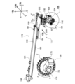
- FIG. 3 is a perspective view of the tool storage section 106 and the tool carrier section 114.
- the tool carrier 114 is provided on the negative side of the X-axis relative to the turret base 102 and the tool storage 106 (see FIG. 1).
- the tool transport section 114 includes a feed mechanism 178 provided along the Z-axis, a carriage 180 that is moved along the Z-axis by the feed mechanism 178, a first hand 182 and a second hand attached to the carriage 180. Including hand 194 and the like.
- the tool conveying section 114 is a mechanism for conveying the tool T including a moving table 180 and a first hand 182 and a second hand 194 attached to the moving table 180 .
- the feed mechanism 178 includes a rail holder 184 arranged parallel to the Z-axis, two guide rails 186 attached to the lower surface of the rail holder 184 in parallel with the Z-axis, and the guide rails 186 engaged with each other.
- a ball screw 190 arranged along the rail holder 184; a ball nut 192 screwed onto the ball screw 190; and a servomotor 196 that rotates the ball screw 190 about its axis.
- a slider 188 is fixed on the upper surface of the moving table 180 .
- a holding member 198 is provided on the lower surface of the moving table 180 so as to be rotatable in the direction of arrows FG (the Y axis is the rotation axis) and movable in the X axis direction.
- the holding member 198 is driven in the X-axis direction by a moving cylinder 200 .
- the holding member 198 is driven by the driving cylinder 202 through a mechanism such as a rack and pinion mechanism, and turns in the directions of arrows FG within an angular range of 90 degrees. That is, the holding member 198 is configured to be planarly movable in the XZ directions and rotatable in the FG directions.
- FIG. 3 shows the state when the holding member 198 rotates in the F direction.
- a rotating shaft 204 is attached through the holding member 198 .
- the rotating shaft 204 is driven by a drive cylinder 206 via a mechanism such as a rack and pinion mechanism, and rotates in the directions of arrows JK within an angular range of 180 degrees.
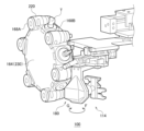
- FIG. 4 is an enlarged perspective view of a portion A shown in FIG. 3.
- FIG. A first hand 182 and a second hand 194 are attached to the ends of the rotating shaft 204 so as to be symmetrical about the axis of the rotating shaft 204 and vertically parallel.
- the first hand 182 and the second hand 194 have the same configuration.
- the first hand 182 has a pair of gripping claws 208 for gripping the tool T, and can grip the tool T with the gripping claws 208 .
- the second hand 194 also has a pair of gripping claws 210 and can grip the tool T with the gripping claws 210 .
- the gripping claws 208 and 210 of the first hand 182 and the second hand 194 move in the Z-axis direction (gripping claws 208 or the like, which is perpendicular to the axial direction of the tool T).
- the grasping claws 208 and 210 of the first hand 182 and the second hand 194 are oriented along the X-axis direction.
- the holding member 198 When the holding member 198 is at the end of movement in the X-axis positive direction (this position is referred to as the "first X position") and at the end of rotation in the F direction, it is held by the holding pot 174 indexed to the attachment/detachment position PM.
- the tool T being held can be gripped by the first hand 182 or the second hand 194 .
- the tool T gripped by the first hand 182 is moved to the holding pot 174 at the attachment/detachment position PM ( empty holding pot).
- the tool transport section 114 is located at an intermediate position between the turret 164 and the tool storage section 106.
- the holding member 198 is moved to the end of movement in the negative direction of the X axis (this position is referred to as the "second X position") and rotated to the end of rotation in the arrow F direction.
- the tool carrier 114 is moved in the Z-axis positive direction to align the axial center (X direction) of the tool T gripped by the first hand 182 with the axial center of the holding pot 174 (the Z coordinate at this time is referred to as the "first Z position").
- the holding member 198 is moved in the positive direction of the X axis to the "first X position", and the tool T of the first hand 182 is attached to the empty holding pot 174 at the attachment/detachment position PM.
- the grip of the tool T by the first hand 182 is released.
- the tool T is not gripped by the gripping claws 208 of the first hand 182, and the tool T is held at the attachment/detachment position PM, the tool T at the attachment/detachment position PM can be taken out by the first hand 182 .
- the tool carrier 114 is positioned between the turret 164 and the tool storage 106 .
- the tool carrier 114 is It is moved to the "first X position", and then the tool carrier 114 is moved to the "first Z position”.
- the tool T attached to the attachment/detachment position PM enters the openings of the pair of gripping claws 208 and is gripped by the gripping claws 208 .
- the holding member 198 is moved to the "second X position”.
- the tool T attached to the holding pot 174 is removed from the holding pot 174 while being gripped by the pair of gripping claws 208 .
- the holding member 198 of the tool transfer section 114 is at the "first X position" and At the end of rotation in the direction of arrow F, the tool T held by the holder 168 can be gripped by the first hand 182 or the second hand 194 positioned below.
- the first hand 182 is positioned on the upper side
- the second hand 194 is positioned on the lower side
- the first hand 182 grips the tool T
- the second hand 194 does not grip the tool T
- the tool T held by the first hand 182 can be exchanged with the tool T held by the holder 168 at the attachment/detachment position PT.
- the tool transport section 114 is located at an intermediate position between the turret 164 and the tool storage section 106.
- the tool carrier 114 is moved to a predetermined position set in the negative direction of the Z axis (this position is (referred to as "3rd Z position").
- the “third Z position” is the position where the lower second hand 194 is located on the Z-axis positive direction side with respect to the tool T held by the holder 168 when the holding member 198 is moved to the "first X position".
- the position, in other words, the second hand 194 is in the front position where the tool T does not interfere.
- the drive cylinder 206 vertically inverts the first hand 182 and the second hand 194, positions the second hand 194 on the upper side, positions the first hand 182 on the lower side, and moves the holding member 198 to the "second hand.” 1X position”.
- the tool T gripped by the first hand 182 is installed at the attachment/detachment position PT.
- the grip of the tool T by the first hand 182 is released.
- the tool T gripped by the first hand 182 is exchanged with the tool T at the attachment/detachment position PT.
- the tool T gripped by the second hand 194 can be stored in the tool storage section 106 by the storage operation described above.
- the holding member 198 is at the rotation end in the direction of arrow G, and the "1st X position", the tool T held by this holder 168 can be gripped by the first hand 182 or the second hand 194 located on the lower side.
- the first hand 182 is positioned on the upper side
- the second hand 194 is positioned on the lower side
- the ball nut 192 grips the tool T
- the second hand 194 does not grip the tool T
- the attachment/detachment When the tool T is held at the position PT, the tool T held by the first hand 182 can be exchanged with the tool T at the attachment/detachment position PT.
- the tool transport section 114 is located at an intermediate position between the turret 164 and the tool storage section 106.
- the holding member 198 is rotated to the rotation end in the direction of arrow G and moved to the "second X position", and the tool carrier 114 is moved to the "third Z position" set in the negative direction of the Z axis.
- the second hand 194 is at a position where it can grip the tool T held by the holder 168 .
- the holding member 198 is moved to the "first X position".
- the tool T at the attachment/detachment position PT enters the openings of the pair of gripping claws 210 and is gripped by the gripping claws 210 .
- the holding member 198 is moved to the “fourth Z position” set in the negative direction of the Z axis, the tool T attached to the holder 168 is taken out from the holder 168 by the grip claws 210 .
- the first hand 182 and the second hand 194 are turned upside down by the drive cylinder 206 so that the second hand 194 is positioned on the upper side and the first hand 182 is positioned on the lower side. Move to "3rd Z position". As a result, the tool T gripped by the first hand 182 is attached to the attachment/detachment position PT. Next, when the holding member 198 is moved to the “second X position”, the grip of the tool T by the first hand 182 is released. Through the second exchange operation described above, the tool T gripped by the ball nut 192 and the tool T at the attachment/detachment position PT are exchanged. The tool T gripped by the second hand 194 can be stored in the tool storage section 106 by the storage operation described above.
- the tool conveying unit 114 is capable of three types of operations: “straight forward”, “turning”, and “rotating”.
- the first “straight forward” is an operation in which the tool carrier 114 moves linearly along the rail holding table 184 (Z-axis).
- Tool transfer between the turret 164 and the tool storage section 106 can be performed by linearly moving the tool transfer section 114 .
- the second “turning” is an operation of turning the tool carrier 114 in the directions indicated by arrows GF. That is, in the present embodiment, the moving table 180, which is a part of the tool carrier 114, has a rotation axis, and rotation around this rotation axis is called "rotation". A turn is a type of rotation, and this turn may be referred to as a first rotation. Either the first holder 168A in the first direction or the second holder 168B in the second direction on the turret 164 is selected as an operation target by the turning motion (details will be described later).
- the third “rotation” is an operation in which the holding member 198 has a rotating shaft 204 and the first hand 182 and the second hand 194 are turned upside down by rotating around this rotating shaft 204 . Since this rotation operation is also one type of rotation, it may be called a second rotation. Either the first hand 182 or the second hand 194 is selected as an operation target by the rotating motion (details will be described later).
- the rotation axis for the first rotation and the rotation axis for the second rotation are in a positional relationship that intersects.
- the rotation axis for the first rotation and the rotation axis for the second rotation may be configured to cross over each other.
- Straight movement, turning movement, and rotation movement each take a certain amount of time, but the time required for straight movement is the longest. In this embodiment, it is assumed that the time required for the turning motion is longer than the time required for the rotating motion.
- Time points are set in advance as numerical values that index the length of time required for each action.
- the time points of straight motion, turning motion, and rotating motion are “5,” “2,” and “1.”
- the time points for straight-ahead movement may be set as 5 points.
- the time point may be a numerical value that indicates the ratio of the time required for each of straight-ahead motion, turning motion, and rotating motion. How to use the time points will be explained later.
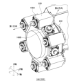
- FIG. 5 is an external perspective view of the turret 164.
- FIG. Turret 164 is rotatably connected to turret base 102 about the Z axis, as described above.
- the turret 164 has a dodecagonal prism shape, and 12 stations 222 (end faces) having insertion holes are formed on its side faces.
- the holder 168 can be inserted into the station 222 as it is, or the cartridge 220 can be inserted. Also, the holder 168 can be inserted into the cartridge 220 .
- the holder 168 is configured to be able to hold a tool T such as an end mill and a drill. Twelve tools T are held by the turret 164 by inserting the shanks of the tools T into the holder 168 .
- the longitudinal direction of the tool T coincides with the "second direction", which is the radial direction of the turret 164.
- the holder 168 directly inserted into the station 222 will be referred to as “second holder 168B”.
- the longitudinal direction of the tool T coincides with the “first direction”, which is the axial direction of the turret 164 .
- the first direction also coincides with the Z-axis negative direction in FIG.
- the holder 168 inserted into the cartridge 220 will be referred to as "first holder 168A”.
- the tool holding direction changes depending on whether they are fixed to the station 222 via the cartridge 220 or not.
- the tool T held by the first holder 168A cuts the inner diameter side of the solid work.
- the second direction tool held by the second holder 168B cuts the outer diameter side of the solid workpiece.
- six tools T are used for inner diameter machining and six tools T are used for outer diameter machining. used for processing.
- a holder 168 to which no tool T is attached is called an "empty holder".
- a cap member may be attached to the holder 168 for covering the hole into which the shank of the tool T is inserted.
- the "empty holder” includes a state in which the tool T is not attached or a case in which the cap member is attached to the hole of the holder.
- FIG. 6 is a hardware configuration diagram of the machine tool 100.
- the machine tool 100 includes an information processor 118 , a machining controller 116 , a machining device 112 , a tool carrier 114 and a tool storage 106 .
- a machining control unit 116 functioning as a numerical controller transmits a control signal to the machining device 112 according to a machining program.
- the processing device 112 moves the turret base 102 according to instructions from the processing control unit 116 to process the workpiece.
- the machining control unit 116 also acquires a “tool pattern” indicating a combination of tools T to be held in the turret 164 from the tool management unit 130 (described later).
- the machining control unit 116 causes the tool transfer unit 114 to perform tool exchange according to the tool pattern instructed by the information processing device 118 .
- the information processing device 118 controls the processing control unit 116 .
- the information processing device 118 provides the operator with a user interface function and manages tool patterns.
- the tool storage section 106 stores spare tools.
- the tool transport section 114 is a mechanism including a moving table 180 and corresponds to a so-called ATC (Automatic Tool Changer).
- the tool transport section 114 takes out the spare tool from the tool storage section 106 according to the replacement instruction from the machining control section 116 and replaces the working tool at the replacement position of the turret 164 with the spare tool.
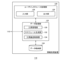
- FIG. 7 is a functional block diagram of the information processing device 118.
- Each component of the information processing device 118 includes computing units such as a CPU (Central Processing Unit) and various co-processors, storage devices such as memory and storage, and hardware including wired or wireless communication lines connecting them. It is implemented by hardware and software stored in a storage device and supplying processing instructions to the computing unit.
- a computer program may consist of a device driver, an operating system, various application programs located in their higher layers, and a library that provides common functions to these programs.
- Each block described below represents a functional block rather than a hardware configuration.
- Each component of the processing control unit 116 also includes a computing unit such as a processor, a storage device such as a memory and a storage, hardware including a wired or wireless communication line connecting them, and processing by the computing unit stored in the storage device. It may be implemented by software providing instructions.
- the processing control unit 116 may be configured as a separate device from the information processing device 118 .
- the information processing device 118 includes a user interface processing unit 120 , a data processing unit 122 and a data storage unit 124 .
- the user interface processing unit 120 is in charge of user interface processing such as image display and audio output, in addition to receiving operations from the user.
- the data processing unit 122 executes various processes based on data acquired by the user interface processing unit 120 and data stored in the data storage unit 124 .
- the data processing section 122 also functions as an interface for the user interface processing section 120 and the data storage section 124 .
- the data storage unit 124 stores various programs and setting data.
- User interface processing section 120 includes an input section 126 and an output section 128 .
- the input unit 126 receives input from the user via a hard device such as a touch panel or a handle.
- the output unit 128 provides various information to the user through image display or audio output.
- the data processing unit 122 includes a tool management unit 130, a schedule generation unit 132 and a tool transfer control unit 134.
- the tool management unit 130 manages tool patterns indicating combinations of working tools to be held by the turret 164 .
- the schedule generator 132 combines the three operations of the tool transporter 114, ie, "straight forward,” “rotation,” and “rotation,” to generate a "transportation schedule” indicating the procedure of tool replacement (described later).
- the tool transfer control unit 134 instructs the machining control unit 116 to control the tool transfer unit 114 according to the transfer schedule, and causes the tool transfer unit 114 (moving table 180) to perform tool exchange.
- the data storage unit 124 stores tool patterns for each machining program.
- the machining control unit 116 appropriately executes tool replacement according to instructions from the tool transfer control unit 134 when executing the machining program.
- the data storage unit 124 also stores spare tool information regarding the types and states (usability) of spare tools stored in the tool storage unit 106 .
- FIG. 8A and 8B are schematic diagrams for explaining straight movement of the tool carrier 114.
- FIG. 8 Since the tool storage section 106 (magazine) and the turret 164 are separated from each other, the tool transport section 114 transports tools by reciprocating (straight forward) between the tool storage section 106 and the turret 164 .
- the second hand 194 has gripping claws on the tool storage section 106 side (hereinafter referred to as "preparation side")
- the first hand 182 has gripping claws on the turret 164 side (hereinafter referred to as "working side”).
- the hand facing the backup side is also called the “preparation hand”
- the hand facing the working side is also called the "working hand”.
- transportation means not only the case where the tool transporter 114 actually carries the tool T, but also the movement between the tool storage unit 106 and the turret 164 in a state where the tool transporter 114 does not hold the tool T. Including cases.
- the tool is indexed to the attachment/detachment position PM of the tool storage section 106 and the second hand 194 (backup hand) does not hold the tool (hereinafter referred to as "empty state").
- the spare tool at the attachment/detachment position PM of the tool storage section 106 is caught by the gripping claws of the second hand 194 (preliminary hand).
- the second hand 194 moves while holding the tool.
- the tool stored in the tool storage section 106 is taken out by the spare hand (the second hand 194 in FIG. 8) of the tool transport section 114 .
- the attachment/detachment position PM of the tool storage section 106 is empty and the second hand 194 (backup hand) holds a tool.
- the tool transport section 114 is moved toward the tool storage section 106 (backup side)
- the tool held by the second hand 194 (backup hand) moves to the attachment/detachment position PM (empty state) of the tool storage section 106.
- the tool carrier 114 is moved toward the turret 164 (working side)
- the tool is left in the holding pot 174 at the attachment/detachment position PM.
- the tool held by the spare hand of the tool conveying section 114 is stored in the tool storage section 106 .
- the second holder 168B is in an empty state at the attachment/detachment position PT of the turret 164, and that the first hand 182 (working hand) of the tool transfer section 114 holds a tool.
- the tool carrier 114 By moving the tool carrier 114 toward the turret 164, the tool held by the first hand 182 (working hand) is attached to the second holder 168B at the attachment/detachment position PT.
- the tool remains in the turret 164 (second holder 168B) when the machining control unit 116 causes the tool transfer unit 114 to move straight toward the tool storage unit 106.
- FIG. 9 is a schematic diagram for explaining the turning motion of the tool carrier 114.
- the machining control unit 116 can axially rotate (rotate about the Y-axis) the tool carrier 114 in the direction of the arrows GF (swivel operation).
- the machining control unit 116 rotates the tool conveying unit 114 to rotate the tool in the first direction held by the first holder 168A (first direction) and the tool in the first direction held by the second holder 168B (second direction). Either of two directional tools can be selected as the object of operation.
- the machining control unit 116 When taking out the tool in the second direction (second holder 168B) from the turret 164, as described above, the machining control unit 116 first rotates the turret 164 and indexes the tool T to the attachment/detachment position PT. Subsequently, the tool in the second direction can be removed from the turret 164 by inserting the tool into the first hand 182 (working hand) and moving the tool transfer section 114 toward the tool storage section 106 .
- the turret 164 When a tool is to be attached to the empty second holder 168B, the turret 164 is rotated to index the empty second holder 168B to the attachment/detachment position PT, and the tool is attached to the second holder 168B from the first hand 182 (working hand). Then, the tool can be attached to the second holder 168B by moving the tool carrier 114 toward the tool storage 106 side.
- the machining control unit 116 rotates the tool conveying unit 114 so that the rotating shaft 204 of the tool conveying unit 114 coincides with the Z-axis direction. Subsequently, the tool T (first holder 168A) indexed to the attachment/detachment position PT is inserted into the first hand 182 (working hand), and the turret 164 is moved toward the tool storage section 106 (Z-axis direction). , the tool that was mounted in the first direction is withdrawn from the turret 164 .
- the turret 164 When attaching a tool to the first holder 168A of the turret 164, after inserting the tool held by the first hand 182 (working hand) into the first holder 168A, the turret 164 is moved to the tool storage section 106 side. , the tool can be removed from the first hand 182 and mounted on the turret 164 in a first orientation.
- the rotation axis 204 of the tool carrier 114 coincides with the axial direction (Z-axis) of the turret 164, and the tool in the first holder 168A (first direction) can be operated.
- the state in which the rotating shaft 204 of the tool carrier 114 is orthogonal to the axial direction of the turret 164 and the tool in the second holder 168B (second direction) can be operated is the state in which the tool is in the "outer turning state”.
- FIG. 8 shows the tool carrier 114 in the outer diameter turning state
- FIG. 9 shows the tool carrier 114 in a state close to the inner diameter turning state.
- FIG. 10A and 10B are schematic diagrams for explaining the rotation operation of the tool carrier 114.
- FIG. The machining control unit 116 drives the rotating shaft 204 to turn the first hand 182 and the second hand 194 upside down.
- one of the first hand 182 and the second hand 194 is on the backup side, and the other is on the working side.
- the first hand 182 holds the tool TA and the second hand 194 is empty.
- the empty second hand 194 can be turned into the working hand by rotating the other hand attached to the turret 164 . can be removed by the second hand 194 .
- FIG. 11 is a flow chart showing the process of generating a transportation schedule.
- a tool change occurs.
- Tool exchange is realized by combining three operations of straight movement, turning, and rotation.
- a tool change is performed when changing the tool arrangement from the pre-change tool pattern in the turret 164 (hereinafter referred to as "current pattern") to the post-change tool pattern (hereinafter referred to as "target pattern").
- the schedule generator 132 In order to minimize the time, the schedule generator 132 generates a transfer schedule in advance before the actual tool change.
- the current pattern is "pre-arrangement information” indicating the arrangement of the tools before the tool change
- the target pattern is “target arrangement information” indicating the arrangement of the tools after the tool change.
- the current pattern as the pre-placement information includes the first hand 182 and the second hand 194 of each station 222 and 114 on the tool post 230 and the placement state of the tool T in each pot that is the mounting position of the tool T in the tool storage section 106. show. Whether or not the tool T is attached at these plurality of attachment positions and which tool is attached are treated as a type of pre-arrangement information. Whether or not the cap member is arranged instead of the tool T as described above is also handled as part of the pre-arrangement information. The same applies to target patterns as target layout information, but the details will be described later with reference to FIG. 14 and subsequent figures.
- the tool management unit 130 sets tool pattern P1 in machining process 1 and sets tool pattern P2 in the next machining process 2 as tool management information in advance. It is registered in the storage unit 124 in advance. That is, before actually machining a workpiece, the tool management unit 130 defines tool patterns P1, P2, P3, . . . for each machining process.
- the schedule generation unit 132 determines the tool transfer order for minimizing the tool change time (work man-hours and work time) when changing from a tool pattern P1 (current pattern) to another tool pattern P2 (target pattern). and registered in the data storage unit 124 as a transfer schedule. For example, the transfer schedule Q (P1, P2) when changing from the tool pattern P1 to the tool pattern P2, the transfer schedule Q (P2, P3) when changing from the tool pattern P2 to the tool pattern P3, . 132 is prepared in advance.
- the tool transfer control unit 134 instructs the machining control unit 116 to control the tool transfer unit 114 according to the transfer schedule Q (P1, P2), thereby executing the tool exchange. be.
- the schedule generator 132 performs a simulation of the first to fifth processes shown below, and then determines a transport schedule with the shortest possible tool change time.
- the schedule generator 132 first moves a tool attached to a certain station 222 (holder 168) to another station 222 (hereinafter referred to as "empty ST") to which no tool is attached.
- the order of transportation is determined (S10). Details of the first step will be described later with reference to FIGS. Note that the empty ST here is synonymous with an empty holder.
- the schedule generation unit 132 determines the tool transfer order for the second step of moving the spare tools stored in the tool storage unit 106 to an empty ST of the turret 164, that is, an empty holder that does not hold the tool T. (S12). Details of the second step will be described later with reference to FIGS.
- the schedule generation unit 132 determines the tool transfer order for the third process of internally exchanging the tools attached to the turret 164 (S14). Details of the third step will be described later with reference to FIGS.
- the schedule generation unit 132 determines the tool transfer order for the fourth step of externally exchanging the work tool on the turret 164 and the spare tool in the tool storage unit 106 (S16). Details of the fourth step will be described later with reference to FIGS.
- the schedule generation unit 132 executes a fifth process for optimizing the transport schedule created through the first to fourth processes (S18). Details of the fifth step will be described later with reference to FIGS. Part of the first to fourth steps may be skipped depending on the current pattern as the pre-placement information and the target pattern as the target placement information (described later).
- the schedule generation unit 132 stores the confirmed transfer schedule in the data storage unit 124 .
- FIG. 12 is a flow chart showing the process of the first step.
- the description will be made on the assumption that the current pattern, which is a tool pattern indicating pre-placement information, is changed to the target pattern, which is another tool pattern indicating target placement information.
- the first step is executed (S32).
- N of S30 When there is no empty ST (N of S30), the first step is skipped.
- FIG. 13 is a flow chart showing the details of the first step in S32 of FIG.
- the schedule generator 132 When the first condition is established between the current pattern and the target pattern (Y in S34), the schedule generator 132 generates a tool transfer order for the first exchange (described later) (S36). After determining the procedure for the first replacement, the schedule generator 132 updates the current pattern as the tool pattern after execution of the first replacement.
- the first condition means that the work tool operable at the current turning position of the tool carrier 114 can be moved to an operable empty ST at the current turning position. For example, when the tool carrier 114 is in the inner diameter turning position, it is necessary to move the work tool held in the first holder 168A (inner diameter) to another first holder 168A (empty ST) (inner diameter). , the first condition is satisfied. After determining the procedure for the first exchange, the process returns to S34.
- the schedule generator 132 When the second condition is established between the current pattern and the target pattern (N in S34, Y in S38), the schedule generator 132 generates a tool transfer order for a second exchange (described later) (S40). After determining the procedure for the second exchange, the schedule generator 132 updates the current pattern.
- the second condition means that the work tool operable at the current turning position of the tool carrier 114 can be moved to an operable empty ST at a turning position different from the current turning position. For example, when the turning position of the tool carrier 114 is at the inner turning position, the working tool held in the first holder 168A (inner diameter) is moved to another second holder 168B (empty ST) (outer diameter). , the second condition is established. After determining the procedure for the second exchange, the process returns to S34.
- the schedule generator 132 When the third condition is established between the current pattern and the target pattern (N in S38, Y in S42), the schedule generator 132 generates a tool transfer order for the third exchange (described later) (S44). After determining the procedure for the third exchange, the schedule generator 132 updates the current pattern.
- the third condition means that a work tool operable at a turning position different from the current turning position of the tool carrier 114 can be moved to an operable empty ST at a turning position different from the current turning position. do. For example, when the turning position of the tool carrier 114 is at the inner turning position, the work tool held by the second holder 168B (outer diameter) is moved to another second holder 168B (empty ST) (outer diameter).
- the third condition is satisfied. After determining the procedure for the third exchange, the process returns to S34.
- the schedule generator 132 When the fourth condition is established between the current pattern and the target pattern (N in S42, Y in S46), the schedule generator 132 generates a tool transfer order for the fourth exchange (described later) (S48). After determining the procedure for the fourth exchange, the schedule generator 132 updates the current pattern.
- the fourth condition means that a work tool operable at a turning position different from the current turning position of the tool carrier 114 can be moved to an operable empty ST at the current turning position. For example, when the turning position of the tool carrier 114 is at the inner turning position, the work tool held in the second holder 168B (outer diameter) is moved to another first holder 168A (empty ST) (inner diameter). , the fourth condition is met. After determining the procedure for the fourth exchange, the process returns to S34.
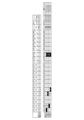
- FIG. 14 is a diagram showing the first transfer order of the first exchange.
- the tool T5 is attached to the station ST1 (outer diameter) and the tool T6 is attached to the station ST2 (outer diameter).
- the target pattern as the target placement information the tool T5 is attached to station ST5 (outer diameter), and the tool T6 is attached to station ST6 (outer diameter). That is, FIG. 14 shows a situation in which two tools attached for outer diameter machining are moved to another holder 168B for outer machining.
- the turning position of the tool conveying unit 114 is in the outer diameter turning state, the first hand 182 is a spare hand, and the second hand 194 is a working hand.
- the tool carrier 114 itself is located on the turret 164 side (working side).
- the schedule generator 132 determines whether the first condition is satisfied in the current pattern and the target pattern, and creates in advance the tool transfer order for changing the tool pattern from the current pattern to the target pattern when the first condition is satisfied. .
- the schedule generator 132 creates two types of tool transfer order, the first transfer order shown in FIG. 14 and the second transfer order shown in FIG. 15, and adopts the better one.
- the tool conveying section 114 is in the outer diameter turning state, the tools T5 and T6 are on the outer diameter side in the current pattern, and the stations ST5 and ST6 to be the destinations are also outside. Since it is on the radial side, the first condition is satisfied.
- the schedule generation unit 132 assumes a case where the tool transfer unit 114 does not simultaneously hold two tools T5 and T6, but transfers the tools one by one.
- the machining control unit 116 executes tool replacement according to the transfer schedule.
- step 1 the second hand 194 (working hand) removes the tool T5 (outer diameter) from the station ST1 (outer diameter). More precisely, the schedule generator 132 simulates the order of tool transfer assuming that the tool T5 (outer diameter) is taken out from the station ST1 (outer diameter) by the second hand 194 in step 1 .
- step 2 the tool T5 (outer diameter) held by the second hand 194 (working hand) is attached to the station ST5 (outer diameter).
- step 3 the second hand 194 (working hand) removes the tool T6 (outer diameter) at station ST2 (outer diameter).
- step 4 the second hand 194 (working hand) attaches the tool T6 (outer diameter) to the station ST6 (outer diameter).
- the schedule generation unit 132 simulates the first transfer order in which the positions of the work tools are changed one by one based on the current pattern, the target pattern, and the initial state of the tool transfer unit 114 . As a result of the simulation, it is found that the number of man-hours (number of steps) required for the first transfer order is 4 steps in total.
- FIG. 15 is a diagram showing the second transfer order of the first exchange.
- the schedule generation unit 132 assumes that the tool transfer unit 114 operates two tools T5 and T6 together.
- Step 1 is the same as the first transport order.
- step 2 the setting of the first hand 182 is changed to the working hand by rotating.
- the second hand 194 becomes the backup hand and the first hand 182 becomes the working hand.
- the second hand 194 (backup hand) holds the tool T5, and the first hand 182 (working hand) is empty.
- step 3 the tool T6 (outer diameter) at station ST2 (outer diameter) is removed by the first hand 182 (working hand).
- the first hand 182 (working hand) holds the tool T6 and the second hand 194 (backup hand) holds the tool T5.
- step 4 the tool T6 is attached to the station ST6 (outer diameter) by the first hand 182 (working hand).
- the second hand 194 holding the tool T5 is changed to a working hand by rotating.
- the second hand 194 (working hand) attaches the tool T5 to the station ST5 (outer diameter).
- the schedule generation unit 132 also simulates a second transfer order in which two tools are moved together based on the current pattern, the target pattern, and the state of the tool transfer unit 114 .
- the work man-hours for the first transfer order were a total of 4 steps, but the work man-hours for the second transfer order were a total of 6 steps. Therefore, the tool change time is shorter in the first transfer order than in the second transfer order. This is because the rotation is performed in steps 2 and 5 in the second transfer order.
- the schedule generation unit 132 When the first condition is satisfied in the current pattern and the target pattern, the schedule generation unit 132 generates a tool transport unit for each of the first transport order in which the tools are moved one by one and the second transport order in which the two tools are moved together. 114 operations are simulated, and the tool transfer order with the smaller number of man-hours (number of steps) is adopted. In the case of the current pattern and the target pattern shown in FIGS. 14 and 15, the first transport order is adopted. After the transfer order is determined, the tool pattern after replacement becomes the next current pattern, and subsequent processing is executed.
- FIG. 16 is a diagram showing the first transport order for the second exchange.
- the tool T7 is attached to station ST1 (outer diameter), and the tool T8 is attached to station ST2 (outer diameter).
- the tool T7 is attached to station ST7 (inner diameter), and the tool T8 is attached to station ST8 (inner diameter).
- the tool conveying section 114 is in the state of outer diameter turning, the first hand 182 is a spare hand, and the second hand 194 is a working hand.
- the tool carrier 114 itself is located on the turret 164 side.
- the second condition is met because the tool carrier 114 is in the outer diameter turning state, the tools T5 and T6 are on the outer diameter side in the current pattern, and the destination stations ST7 and ST8 are on the inner diameter side.
- the tool transfer section 114 transfers the tools T7 and T8 one by one.
- step 1 the tool T7 (outer diameter) at station ST1 (outer diameter) is picked up by the second hand 194 (working hand).
- step 2 the tool carrier 114 is set to the inner diameter turning state by the turning motion.
- step 3 the second hand 194 (working hand) attaches the tool T7 to the station ST7 (inner diameter).
- step 4 the tool carrier 114 is turned again and set to the outer diameter turning state.
- step 5 the second hand 194 (working hand) removes the tool T8 from the station ST2 (outer diameter). is attached.
- the schedule generation unit 132 simulates the first transfer order in which the tool transfer unit 114 changes the positions of the tools one by one based on the current pattern, the target pattern, and the state of the tool transfer unit 114 .
- the work man-hours for the first transfer order shown in FIG. 16 are a total of 7 steps.
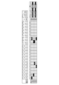
- FIG. 17 is a diagram showing the second transport order for the second exchange.
- the schedule generation unit 132 assumes that the tool transport unit 114 transports two tools T7 and T8 at the same time.
- Step 1 is the same as the first transport order.
- the second hand 194 holding the tool T7 becomes a spare hand and the empty first hand 182 becomes a working hand due to the rotating operation.
- the tool T8 (outer diameter) at station ST2 is picked up by the first hand 182 (working hand).
- step 4 the tool transfer section 114 is set to the inside turning state, and in step 5, the tool T8 is attached from the first hand 182 (working hand) to the station ST8 (inner diameter).
- step 6 the second hand 194 holding the tool T7 becomes the working hand by rotating.
- step 7 the tool T7 is attached from the second hand 194 (working hand) to the station ST7 (inner diameter side).
- both the work man-hours for the first transfer order shown in FIG. 16 and the work man-hours for the second transfer order shown in FIG. 17 total 7 steps.
- the schedule generation unit 132 calculates the total value of the time points for the first order of transportation and the second order of transportation. In the first transport order, three turning motions (two points) occur, so the total number of time points is six. On the other hand, in the second transport order, one turning operation (2 points) and two rotating operations (1 point) occur, so the total number of time points is 4 points. Since the second transfer order is superior when compared at time points, the schedule generator 132 adopts the second transfer order for the second exchange. After the transfer order is determined, the tool pattern after replacement becomes the current pattern for the next process.
- the schedule generator 132 adopts the first transport order shown as the first example.
- FIG. 18 is a diagram showing the first transfer order of the third exchange.
- the tool T10 is attached to station ST7 (inner diameter), and the tool T11 is attached to station ST8 (inner diameter).
- the tool T10 is attached to station ST10 (inner diameter)
- the tool T11 is attached to station ST11 (inner diameter).
- the tool conveying section 114 is in the state of outer diameter turning
- the first hand 182 is a spare hand
- the second hand 194 is a working hand.
- the tool carrier 114 itself is located on the turret 164 side (working side).
- the tool carrier 114 Since the tool carrier 114 is in the outer diameter turning state, the tools T10 and T11 are on the inner diameter side in the current pattern, and the destination stations ST10 and ST11 are also on the inner diameter side, the third condition is satisfied. In the first transfer order shown in FIG. 18, it is assumed that the tool transfer section 114 transfers the tools T10 and T11 one by one.
- step 1 the tool carrier 114 is set to the inner diameter turning state by turning operation.
- step 2 the second hand 194 (working hand) removes the tool T10 from the station ST7 (inner diameter side).
- step 3 the second hand 194 (working hand) attaches the tool T7 to the station ST10 (inner diameter side).
- step 4 the tool T11 of station ST8 (inner diameter) is removed by the second hand 194 (working hand), and in step 5, the tool T11 is attached to station ST11 (inner diameter).
- the schedule generation unit 132 simulates the first transfer order in which the tool transfer unit 114 changes the positions of the tools one by one based on the current pattern, the target pattern, and the state of the tool transfer unit 114 .
- the work man-hours for the first transfer order shown in FIG. 18 are five steps in total.
- FIG. 19 is a diagram showing the second transfer order of the third exchange. In the second carrying order shown in FIG. 19, it is assumed that the tool carrying section 114 carries two tools T10 and T11 at the same time.
- Steps 1 and 2 are the same as in the first transportation order.
- step 3 a rotating operation is performed, and the second hand 194 holding the tool T10 is used as a spare hand, and the empty first hand 182 is used as a working hand.
- step 4 the tool T11 at station ST8 (inner diameter) is removed by the first hand 182 (working hand).
- the tool T11 is attached to the station ST11 by the first hand 182 (working hand).
- the second hand 194 holding the tool T10 is set as the working hand by rotating.
- the second hand 194 (working hand) attaches the tool T10 to the station ST10 (inner diameter side).
- the work man-hours for the first transfer order shown in FIG. 18 are a total of 5 steps, and the work man-hours for the second transfer order shown in FIG. 19 are a total of 7 steps. Therefore, the schedule generator 132 adopts the first transport order. After the transfer order is determined, the tool pattern after replacement becomes the next current pattern.
- FIG. 20 is a diagram showing the first transport order for the fourth exchange.
- the tool T1 is attached to station ST7 (inner diameter), and the tool T2 is attached to station ST8 (inner diameter).
- the tool T1 is attached to station ST1 (outer diameter), and the tool T2 is attached to station ST2 (outer diameter).
- the tool conveying section 114 is in an outer diameter turning state
- the first hand 182 is a backup hand
- the second hand 194 is a working hand.
- the tool carrier 114 itself is located on the turret 164 side (working side).
- the fourth condition is met because the tool carrier 114 is in the outer diameter turning state, the tools T1 and T2 are on the inner diameter side in the current pattern, and the destination stations ST1 and ST2 are on the outer diameter side.
- the tool transfer section 114 transfers the tools T1 and T2 one by one.
- step 1 the tool transfer section 114 is set to the inner diameter turning state by turning operation.
- step 2 the second hand 194 (working hand) removes the tool T1 from the station ST1 (inner diameter), and in step 3, the tool conveying section 114 is reset to the outer diameter turning state.
- step 4 the second hand 194 (working hand) attaches the tool T1 to the station ST1 (outer diameter).
- step 5 the tool conveying unit 114 is returned to the inside turning state, and in step 6, the tool T2 of station ST8 (inner diameter) is removed by the second hand 194 (working hand).
- step 7 the tool transfer section 114 is returned to the outer diameter turning state, and at step 8, the tool T2 is attached to the station ST2 (outer diameter) by the second hand 194 (working hand).
- the schedule generation unit 132 simulates the first transfer order in which the tool transfer unit 114 changes the positions of the tools one by one based on the current pattern, the target pattern, and the state of the tool transfer unit 114 .
- the work man-hours for the first transfer order shown in FIG. 20 are eight steps in total.
- FIG. 21 is a diagram showing the second transfer order of the fourth exchange.
- the tool conveying section 114 conveys two tools T1 and T2 at the same time.
- Steps 1 and 2 are the same as in the first transportation order.
- the second hand 194 holding the tool T1 by rotating operation is set as a spare hand, and the empty first hand 182 is set as a working hand.
- the tool T2 at station ST8 (inner diameter) is removed by the first hand 182 (working hand).
- step 5 the tool conveying unit 114 is returned to the outer diameter turning state, and in step 6, the tool T2 is attached to station ST2 (outer diameter) by the first hand 182 (working hand).
- step 7 the second hand 194 holding the tool T1 is set as the working hand by rotating.
- step 8 the second hand 194 (working hand) attaches the tool T1 to the station ST1 (outer diameter).
- both the man-hours for the first transfer order shown in FIG. 20 and the man-hours for the second transfer order shown in FIG. 21 are 7 steps in total.
- the first transport order four turning motions (two points) occur, so the total number of time points is eight.
- the second transport order there are two turning motions (2 points) and two rotating motions (1 point), so the total number of time points is 6 points.
- the second transfer order is superior. After the transfer order is determined, the target pattern becomes the next current pattern. It should be noted that if the rotation operation takes more time than the rotation operation, the schedule generator 132 adopts the first transfer order.
- FIG. 22 is a flow chart showing the process of the second step.
- the second process is executed (S62).
- N of S60 When there is no empty ST (N of S60), the second step is skipped.
- FIG. 23 is a flow chart showing the details of the second step in S62 of FIG.
- the schedule generation unit 132 takes out two tools from the tool storage unit 106, transports them, and attaches the tools to the turret 164 (S72). After mounting the tool, the schedule generator 132 updates the current pattern, and the process returns to S70.
- the schedule generation unit 132 takes out one tool from the tool storage unit 106, transports it, and executes external replacement ( S76). After mounting the tool, the schedule generator 132 updates the current pattern, and the process returns to S34. When no empty ST remains in the turret 164 (N of S74), the second step ends.
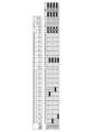
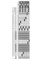
- 24A and 24B are diagrams showing the first conveying order when two sheets are conveyed in the second step.
- station ST1 outer diameter
- station ST2 outer diameter
- station ST7 inner diameter
- station ST8 inner diameter
- Tools T1, T2, T7 and T8 are held in holding pots MG1, MG2, MG3 and MG4 of the tool storage section 106, respectively.
- the target pattern as the target arrangement information, the tool T1 is attached to station ST1 (outer diameter), the tool T2 is attached to station ST2 (outer diameter), the tool T7 is attached to station ST7 (inner diameter), and the tool T8 is attached to station ST8 (inner diameter).
- the tool conveying section 114 is in an outer diameter turning state, the first hand 182 is set as a backup hand, and the second hand 194 is set as a working hand.
- the tool carrier 114 itself is located on the side of the tool storage 106 (reserve side).
- FIG. 24 and the following FIG. 25 show simulation results corresponding to the two-tool transfer in S72 of FIG.
- first transfer order shown in FIG. 24 after tools T1 and T2 are attached to station ST1 (outer diameter) and station ST2 (outer diameter), tools T7 and T8 are attached to station ST7 (inner diameter) and station ST8 (inner diameter). Assume that it is installed.
- step 1 the tool T1 is taken out from the holding pod MG1 by the first hand 182 (backup hand), in step 2, the second hand 194 is set as the backup hand by a rotating operation, and in step 3, the second hand 194 removes the tool T1 from the holding pod MG2. Take out the tool T2.
- step 4 the tool transfer section 114 is moved straight toward the turret 164 while holding the tool T2 in the first hand 182 (working hand) and the tool T1 in the second hand 194 (backup hand).
- step 5 the tool T1 is attached to the station ST1 (outer diameter) by the first hand 182 (working hand).
- the tool T2 is attached to the station ST2 (outer diameter) by hand).
- the tool transport section 114 returns to the tool storage section 106 side.
- the tool T7 is taken out from the holding pod MG3 by the first hand 182 (backup hand), at step 10, a rotation operation is performed to set the second hand 194 as the backup hand, and at step 11, the second hand 194 (backup hand) is set as the backup hand.
- the tool T8 is taken out from the holding pod MG4 by hand).
- the first hand 182 (working hand) holds the tool T7
- the second hand 194 (backup hand) holds the tool T8.
- step 12 the tool carrier 114 is moved straight toward the turret 164.
- step 13 the tool carrier 114 is set to the inner diameter turning state. Install tool T7.
- the tool transfer section 114 is rotated to set the second hand 194 as the working hand, and at step 16, the second hand 194 (working hand) attaches the tool T8 to the station ST8 (inner diameter).
- the outer diameter side tools T1 and T2 are attached to the turret 164 from the tool storage section 106, and then the inner diameter side tools T7 and T8 are attached. Can be changed.
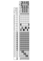
- FIG. 25 is a diagram showing a second transfer order when two sheets are transferred in the second step.
- tools T1 and T7 are attached to station ST1 (outer diameter) and station ST7 (inner diameter)
- tools T2 and T8 are attached to station ST2 (outer diameter) and station ST8 (inner diameter). Assume that it is installed.
- Steps 1 and 2 are the same as in the first transportation order.
- the tool T7 is taken out from the holding pod MG3 by the second hand 194 (backup hand), and in step 4, the tool conveying section 114 conveys the tools T1 and T7 to the turret 164 side.
- the tool T1 is attached to the station ST1 (outside diameter) by the first hand 182 (working hand).
- the second hand 194 (working hand) attaches the tool T7 to the station ST7 (inner diameter).
- the outer diameter turning state is set, at step 10 the tool conveying unit 114 moves to the tool storage unit 106 side, at step 11 the tool T2 is taken out from the holding pot MG2 by the first hand 182 (backup hand), and step At 12 a rotation operation is performed. Due to this rotating operation, the second hand 194 becomes a backup hand. At step 13, the tool T8 is taken out from the holding pod MG4 by the second hand 194 (backup hand), and at step 14, the tool transport section 114 transports the tools T2 and T8 to the turret 164 side.
- step 15 After the tool T2 is attached to the station ST2 (outer diameter) by the first hand 182 (working hand) in step 15, the inside turning state is entered in step 16, and the tool conveying section 114 is rotated in step 17 to rotate the second hand 194. is set as the working hand, and in step 18, the second hand 194 (working hand) attaches the tool T8 to the station ST8.
- the schedule generation unit 132 adopts the first transportation order.
- two-tool transfer (S72 in FIG. 23), a plurality of tools in the same direction, such as outer diameter and outer diameter, or inner diameter and inner diameter, are collectively conveyed to reduce the number of turning operations. can be done.
- FIG. 26 is a flow chart showing the process of the third step. If the tool change is completed after performing either or both of the first and second steps, then there is no need to perform the third step.
- the second step or after skipping of the second step when there is a need to internally replace the tool pattern (Y in S80), that is, the tool TA attached to one station and the tool TA attached to another station
- a third step is performed (S82) when it is necessary to change the position of the tool TB to be replaced.
- N of S80 the third step is skipped.
- FIG. 27 is a diagram showing the first transfer order in the third step.
- tools T3, T1, and T2 are attached to station ST1 (outer diameter), station ST2 (outer diameter), and station ST3 (outer diameter).
- the tool T1 is attached to station ST1 (outer diameter)
- the tool T2 is attached to station ST2 (outer diameter)
- the tool T3 is attached to station ST3 (outer diameter).
- the tool conveying section 114 is in an outer diameter turning state
- the first hand 182 is a spare hand
- the second hand 194 is a working hand.
- the tool carrier 114 itself is located on the turret 164 side (working side).
- step 1 the second hand 194 (working hand) picks up the tool T3 from the station ST1 (outer diameter).
- a tool T1 is taken out from the station ST2 (outer diameter) by a hand 182 (working hand).
- step 4 the tool T1 is attached to the empty station ST1 (outer diameter) by the first hand 182 (working hand).
- the tool T3 is temporarily installed in the vacant station ST2 (outer diameter) by the second hand 194 (working hand).
- step 7 the tool T3 is again removed from the station ST2 by the second hand 194 (working hand).
- the tool T2 is taken out from the station ST3 (outer diameter) by the (working hand), and in step 10, the tool T2 is attached to the station ST2 by the first hand 182 (working hand).
- the second hand 194 is set as the working hand by rotating the tool transporting unit 114, and at step 12, the second hand 194 (working hand) attaches the tool T3 to the station ST3.
- the work man-hour for the first transfer order in the third step is 12 steps.
- FIG. 28 is a diagram showing the second transfer order in the third step.
- the tools T1, T2, and T3 are circulated among stations ST1 (outer diameter), station ST2 (outer diameter), and station ST3 (outer diameter).
- Steps 1 to 4 are the same as in the first transport order.
- the first hand 182 (working hand) picks up the tool T2 from the station ST3 (outer diameter)
- the first hand 182 (working hand) attaches the tool T2 to the station ST2.
- the tool conveying unit 114 is rotated to set the second hand 194 as the working hand, and in step 8, the second hand 194 (working hand) attaches the tool T3 to the station ST3 (outer diameter).
- the number of man-hours for the second transport order is 8 steps. Therefore, the schedule generator 132 adopts the second transport order.
- FIG. 29 is a flow chart showing the process of the fourth step. If the tool change is completed after performing both or one of the first and second steps, it is not necessary to perform not only the third step but also the fourth step.
- Y in S90 execution of the third step or when the tool pattern after skipping the third step needs to be replaced externally
- S92 a fourth step is performed (S92). When there is no need for external replacement (N of S90), the fourth step is skipped.
- FIG. 30 is a diagram showing the first transfer order in the fourth step.
- tools T15, T1, and T2 are attached to station ST1 (outer diameter), station ST2 (outer diameter), and station ST3 (outer diameter).
- a tool T3 is stored in the holding pod MG1 of the tool storage section 106.
- the tool T1 is attached to station ST1 (outer diameter)
- the tool T2 is attached to station ST2 (outer diameter)
- the tool T3 is attached to station ST3 (outer diameter).
- the tool conveying section 114 is in an outer diameter turning state
- the first hand 182 is set as a backup hand
- the second hand 194 is set as a working hand.
- the tool carrier 114 itself is located on the side of the tool storage 106 (reserve side).
- tools T1 and T2 are in stations ST1 and ST2 and tool T3 is in tool storage section 106, and tools T1 and T2 are temporarily retracted to tool storage section 106 (hereinafter referred to as “Temporary Evacuation”).
- step 1 the tool T3 is taken out from the holding pod MG1 by the first hand 182 (backup hand), and in step 2, the tool transport section 114 transports the tool T3 to the turret 164 side.
- step 3 the tool T2 is taken out from the turret 164 by the second hand 194 (working hand).
- the tool T3 is attached to the station ST3 by (working hand).
- step 6 the tool conveying unit 114 conveys the tool T2 to the tool storage unit 106 side
- step 7 the second hand 194 (backup hand) temporarily retracts the tool T2 to the holding pod MG1
- step 8 the The tool T2 is taken out from the tool storage section 106 by the second hand 194 (backup hand), and in step 9 the tool T2 is carried to the turret 164 side again.
- the tool T1 is taken out from the station ST2 by the first hand 182 (working hand).
- the tool carrier 114 is rotated to set the second hand 194 as the working hand.
- the tool T2 is attached to the station ST2 (outer diameter) by a work hand).
- the tool T1 is transported to the tool storage section 106, and in step 14, the tool T1 is temporarily retracted to the tool storage section 106.
- step 15 the first hand 182 (backup hand) takes out the tool T1 from the tool storage section 106.
- the tool T1 is carried to the turret 164 side. Remove tool T15.
- the first hand 182 is set as the working hand by rotating the tool conveying unit 114.
- the first hand 182 (working hand) attaches the tool T1 to the station ST1 (outer diameter).
- the tool T15 is stored in the tool storage section 106 by the second hand 194 (backup hand).
- FIG. 31 is a diagram showing the second transfer order in the fourth step. Steps 1 to 5 are the same as in the first transfer order.
- the first hand 182 (working hand) removes the tool T1 from the station ST2 (outer diameter).
- the tool carrier 114 is rotated to set the second hand 194 as the working hand. Then, the second hand 194 (working hand) picks up the tool T15 from the station ST1 (outer diameter).
- the tool conveying unit 114 is rotated to set the first hand 182 as the working hand, and at step 11, the first hand 182 (working hand) attaches the tool T1 to the station ST1 (outer diameter).
- the tool conveying section 114 conveys the tool T15 to the tool storage section 106, and in step 13, the tool T15 is stored in the tool storage section 106 by the second hand 194 (backup hand).
- the schedule generator 132 adopts the second transport order.
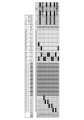
- FIG. 32 is a diagram showing a transfer schedule before execution of the fifth process in the first example.
- the schedule generator 132 further executes the fifth step for determining whether the transfer schedule can be optimized.
- a transfer schedule for both or one of the first process and the second process is generated, and this transfer schedule is used.
- a decision is made as to whether optimization is possible based on Optimization conditions can be set arbitrarily. For example, in straight movement (carrying tools), it is conceivable to carry two tools together as much as possible, or to give priority to removing unnecessary tools from the turret 164 .
- the fifth step will be described separately for the first example and the second example. A first example will be described with reference to FIGS. 32 and 33, and a second example will be described with reference to FIGS. 34 and 35.
- FIG. 32 and 33 A first example will be described with reference to FIGS. 32 and 33, and a second example will be described with reference to FIGS. 34 and 35.
- tools T15, T1, and T2 are attached to station ST1 (outer diameter), station ST2 (outer diameter), and station ST3 (outer diameter).
- Tools T3 and T4 are stored in the holding pods MG1 and MG2 of the tool storage section 106, respectively.
- the tool T1 is attached to station ST1 (outer diameter)
- the tool T2 is attached to station ST2 (outer diameter)
- the tool T3 is attached to station ST3 (outer diameter)
- the tool T4 is attached to station ST4 (outer diameter).
- the tool conveying section 114 is in an outer diameter turning state, the first hand 182 is a spare hand, and the second hand 194 is a working hand.
- the tool carrier 114 itself is located on the side of the tool storage 106 (reserve side).
- the schedule generator 132 executes the fifth step (optimization process) to confirm whether the transfer schedule shown in FIG. 32 is the optimum solution.
- FIG. 33 is a diagram showing a transfer schedule after execution of the fifth process in the first example.
- the tool transfer section 114 rotates with the first hand 182 holding the tool T4, and in step 4, the first hand 182 (work The tool T4 is attached to the station ST4 by hand).
- the tool transfer section 114 takes out the tool T3 from the tool storage section 106 in addition to the tool T4.
- the tool transfer section 114 takes out the tools T3 and T4 from the tool storage section 106 and then transfers them together, thereby suppressing the total number of steps to 16. Therefore, the schedule generation unit 132 adopts the transfer schedule after execution of the fifth process, not the transfer schedule before execution of the fifth process shown in FIG. However, it may not be optimal for the tool carrier 114 to carry two tools. A second example describes such a case.
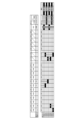
- FIG. 34 is a diagram showing a transfer schedule before execution of the fifth step in the second example.
- tools T15, T8 and T7 are attached to station ST1 (outer diameter), station ST7 (inner diameter) and station ST8 (inner diameter).
- Tools T1 and T9 are stored in the holding pods MG1 and MG2 of the tool storage section 106, respectively.
- the tool T1 is attached to station ST1 (outer diameter)
- the tool T7 is attached to station ST7 (inner diameter)
- the tool T8 is attached to station ST8 (inner diameter)
- the tool T9 is attached to station ST9 (inner diameter).
- the tool conveying section 114 is in an outer diameter turning state, the first hand 182 is set as a backup hand, and the second hand 194 is set as a working hand.
- the tool carrier 114 itself is located on the side of the tool storage 106 (reserve side).
- FIG. 35 is a diagram showing a transfer schedule after execution of the fifth step in the second example.
- the transfer schedule before execution of the fifth step four straight movements occur, but in each case the tool transfer section 114 transfers only one tool.
- the tool transfer section 114 transfers the tools T9 and T1 in step 14 among them.
- the total number of steps after execution of the fifth step is 22, which is greater than that before execution of the fifth step. Therefore, the schedule generator 132 adopts the transfer schedule before execution of the fifth step.
- the schedule generation unit 132 executes the first step and the second step, and creates the tool transfer order so that no empty ST remains in the turret 164 after the execution of the second step. Since the third step is internal replacement, it is necessary to position the tool carrier 114 on the turret 164 side. Since the tool carrier 114 is on the turret 164 side at the end of the second step, there is no need to move the tool carrier 114 to the turret 164 side at the start of the third step. On the other hand, since the fourth step is an external replacement, it is necessary to position the tool transport section 114 on the tool storage section 106 side. For the above reasons, it is desirable to perform the third step instead of the fourth step after the first and second steps.
- the schedule generator 132 may skip the first and second processes and generate a transport schedule based on the algorithm for the third and subsequent processes. In this case, the schedule generator 132 may execute the fourth step before the third step.
- the schedule generation unit 132 may calculate the tool transfer order by round-robin for various combinations such as from which tool to move and from which station 222 to move the tool first. good. For example, even in the first step, it is possible to create various tool transfer orders based on the combination of the current pattern and the target pattern.
- the schedule generation unit 132 may select the most efficient tool transfer order from among many tool transfer orders generated in this way.
- the schedule generating unit 132 can reduce the number of man-hours required for tool replacement by arranging a transfer schedule so that temporary evacuation to the tool storage unit 106 and temporary installation to the turret 164 do not occur.
- the schedule generation unit 132 determines which transport order is the most work based on the time points indexed for the time required for each of the transport operation, the turning operation, and the rotating operation. You can judge whether it is efficient or not.
- part of the first to fifth steps may be skipped.
- the tool change may be completed by executing the first and second steps, so in this case, the third and subsequent steps are unnecessary.
- the total time related to machining, including tool setup can be shortened. Therefore, it is possible to provide a machine tool or the like with improved energy efficiency.
- the first holder 168A is "a holder 168 that holds a tool for cutting the inner diameter side of a work”
- the second holder 168B is "a holder 168 that holds a tool for cutting the outer diameter side of a work”.
- the present invention is not limited to inner diameter/outer diameter and is applicable to cases where a plurality of tool holding methods are possible in the turret 164 .
- first direction and second direction are arbitrary, and may not be perpendicular to each other.
- Some tools T can handle both turning and rotary machining.
- the turning holder 168M is attached to the station 222 and the tool T is attached to the turning holder 168M, this tool T is used for turning.
- the rotary holder 168N is attached to the station 222 and the same type of tool T is attached to the rotary holder 168N, this tool T is used for rotary machining.
- the schedule generator 132 can similarly generate a transfer schedule in tool exchange targeting the turret 164 including both the turning holder 168M and the rotary holder 168N.
- a predetermined number of tools T for example, only one tool T, are attached from a state in which all stations 222 are empty STs.
- a predetermined number of tools T are transported from the tool storage section 106 and the tools are attached to all or part of the 12 empty STs.
- a predetermined number of tools for example, one tool may be removed from a state in which tools are attached to all stations 222 .
- a predetermined number of tools T less than 12 may be transported from the tool post 230 and stored in the tool storage section 106 .
Landscapes
- Engineering & Computer Science (AREA)
- Mechanical Engineering (AREA)
- Automatic Tool Replacement In Machine Tools (AREA)
- Multi-Process Working Machines And Systems (AREA)
Priority Applications (1)
| Application Number | Priority Date | Filing Date | Title |
|---|---|---|---|
| JP2023552327A JPWO2023149134A1 (https=) | 2022-02-01 | 2022-12-26 |
Applications Claiming Priority (2)
| Application Number | Priority Date | Filing Date | Title |
|---|---|---|---|
| JP2022-013925 | 2022-02-01 | ||
| JP2022013925A JP7203254B1 (ja) | 2022-02-01 | 2022-02-01 | 工作機械 |
Publications (1)
| Publication Number | Publication Date |
|---|---|
| WO2023149134A1 true WO2023149134A1 (ja) | 2023-08-10 |
Family
ID=84887133
Family Applications (1)
| Application Number | Title | Priority Date | Filing Date |
|---|---|---|---|
| PCT/JP2022/047803 Ceased WO2023149134A1 (ja) | 2022-02-01 | 2022-12-26 | 工作機械 |
Country Status (2)
| Country | Link |
|---|---|
| JP (2) | JP7203254B1 (https=) |
| WO (1) | WO2023149134A1 (https=) |
Families Citing this family (1)
| Publication number | Priority date | Publication date | Assignee | Title |
|---|---|---|---|---|
| JPWO2024134739A1 (https=) * | 2022-12-19 | 2024-06-27 |
Citations (4)
| Publication number | Priority date | Publication date | Assignee | Title |
|---|---|---|---|---|
| JP2006326709A (ja) * | 2005-05-24 | 2006-12-07 | Murata Mach Ltd | 工具ホルダチェンジャー制御プログラム作成装置 |
| WO2022004123A1 (ja) * | 2020-06-29 | 2022-01-06 | Dmg森精機株式会社 | 情報処理システムおよび工作機械 |
| JP2022016711A (ja) * | 2020-06-29 | 2022-01-24 | Dmg森精機株式会社 | 工作機械 |
| WO2022018923A1 (ja) * | 2020-07-20 | 2022-01-27 | Dmg森精機株式会社 | 工作機械 |
Family Cites Families (4)
| Publication number | Priority date | Publication date | Assignee | Title |
|---|---|---|---|---|
| JP2010099782A (ja) * | 2008-10-24 | 2010-05-06 | Fuji Mach Mfg Co Ltd | 工作機械及び工具交換方法 |
| JP6778311B1 (ja) * | 2019-11-01 | 2020-10-28 | Dmg森精機株式会社 | 刃物台および工作機械 |
| KR102813106B1 (ko) * | 2020-04-21 | 2025-05-29 | 주식회사 디엔솔루션즈 | 공작기계의 터렛 공구대 장치 |
| JP7137723B1 (ja) * | 2022-02-01 | 2022-09-14 | Dmg森精機株式会社 | 工作機械 |
-
2022
- 2022-02-01 JP JP2022013925A patent/JP7203254B1/ja active Active
- 2022-12-26 JP JP2023552327A patent/JPWO2023149134A1/ja active Pending
- 2022-12-26 WO PCT/JP2022/047803 patent/WO2023149134A1/ja not_active Ceased
Patent Citations (4)
| Publication number | Priority date | Publication date | Assignee | Title |
|---|---|---|---|---|
| JP2006326709A (ja) * | 2005-05-24 | 2006-12-07 | Murata Mach Ltd | 工具ホルダチェンジャー制御プログラム作成装置 |
| WO2022004123A1 (ja) * | 2020-06-29 | 2022-01-06 | Dmg森精機株式会社 | 情報処理システムおよび工作機械 |
| JP2022016711A (ja) * | 2020-06-29 | 2022-01-24 | Dmg森精機株式会社 | 工作機械 |
| WO2022018923A1 (ja) * | 2020-07-20 | 2022-01-27 | Dmg森精機株式会社 | 工作機械 |
Also Published As
| Publication number | Publication date |
|---|---|
| JPWO2023149134A1 (https=) | 2023-08-10 |
| JP7203254B1 (ja) | 2023-01-12 |
| JP2023112260A (ja) | 2023-08-14 |
Similar Documents
| Publication | Publication Date | Title |
|---|---|---|
| EP2065110B1 (en) | Automatic chuck jaw change system in combined machining lathe | |
| US9211619B2 (en) | Method and machine tool for machining a workpiece | |
| JP6212905B2 (ja) | 工作機械 | |
| JP2019010726A (ja) | 工作物を機械加工する工作機械 | |
| JP6779406B1 (ja) | 工作機械 | |
| JP7203254B1 (ja) | 工作機械 | |
| JP5687854B2 (ja) | 多面加工機 | |
| JP7137722B1 (ja) | 工作機械 | |
| US20230278152A1 (en) | Machine tool | |
| WO2022004252A1 (ja) | 工作機械 | |
| WO2008016069A1 (fr) | Machine de traitement d'ouvrage, système de traitement d'ouvrage et procédé de traitement d'ouvrage utilisant la machine de traitement d'ouvrage | |
| JP4330413B2 (ja) | 自動工具交換装置 | |
| JP7019085B1 (ja) | 工作機械 | |
| JP7451068B1 (ja) | 工作機械 | |
| JP2013141727A (ja) | 複合加工機 | |
| CN108568688B (zh) | 机床 | |
| JP4330403B2 (ja) | 工作機械 | |
| JP7446514B1 (ja) | 工作機械、ワークの加工方法および制御プログラム | |
| JPS6389235A (ja) | 複軸式マシニングセンタと、その工具交換方法 | |
| JP2589462Y2 (ja) | 対向主軸形複合工作機械 | |
| JP5329049B2 (ja) | ワーク加工機 | |
| JPH04128134U (ja) | 工具交換装置付nc旋盤 | |
| JP4301208B2 (ja) | 工具ホルダチェンジャー制御プログラム作成装置 | |
| JP2000061761A (ja) | 直交座標マトリックス形工具マガジンにおける工具搬送方法 | |
| JP2006326711A (ja) | 工具ホルダチェンジャー動作情報作成装置 |
Legal Events
| Date | Code | Title | Description |
|---|---|---|---|
| WWE | Wipo information: entry into national phase |
Ref document number: 2023552327 Country of ref document: JP |
|
| 121 | Ep: the epo has been informed by wipo that ep was designated in this application |
Ref document number: 22925036 Country of ref document: EP Kind code of ref document: A1 |
|
| NENP | Non-entry into the national phase |
Ref country code: DE |
|
| 122 | Ep: pct application non-entry in european phase |
Ref document number: 22925036 Country of ref document: EP Kind code of ref document: A1 |