WO2023089854A1 - 配管支持部材 - Google Patents
配管支持部材 Download PDFInfo
- Publication number
- WO2023089854A1 WO2023089854A1 PCT/JP2022/023440 JP2022023440W WO2023089854A1 WO 2023089854 A1 WO2023089854 A1 WO 2023089854A1 JP 2022023440 W JP2022023440 W JP 2022023440W WO 2023089854 A1 WO2023089854 A1 WO 2023089854A1
- Authority
- WO
- WIPO (PCT)
- Prior art keywords
- holding
- nut
- bolt
- pipe
- tightening
- Prior art date
- Legal status (The legal status is an assumption and is not a legal conclusion. Google has not performed a legal analysis and makes no representation as to the accuracy of the status listed.)
- Ceased
Links
Images




Classifications
-
- F—MECHANICAL ENGINEERING; LIGHTING; HEATING; WEAPONS; BLASTING
- F16—ENGINEERING ELEMENTS AND UNITS; GENERAL MEASURES FOR PRODUCING AND MAINTAINING EFFECTIVE FUNCTIONING OF MACHINES OR INSTALLATIONS; THERMAL INSULATION IN GENERAL
- F16L—PIPES; JOINTS OR FITTINGS FOR PIPES; SUPPORTS FOR PIPES, CABLES OR PROTECTIVE TUBING; MEANS FOR THERMAL INSULATION IN GENERAL
- F16L3/00—Supports for pipes, cables or protective tubing, e.g. hangers, holders, clamps, cleats, clips, brackets
- F16L3/08—Supports for pipes, cables or protective tubing, e.g. hangers, holders, clamps, cleats, clips, brackets substantially surrounding the pipe, cable or protective tubing
- F16L3/12—Supports for pipes, cables or protective tubing, e.g. hangers, holders, clamps, cleats, clips, brackets substantially surrounding the pipe, cable or protective tubing comprising a member substantially surrounding the pipe, cable or protective tubing
-
- F—MECHANICAL ENGINEERING; LIGHTING; HEATING; WEAPONS; BLASTING
- F16—ENGINEERING ELEMENTS AND UNITS; GENERAL MEASURES FOR PRODUCING AND MAINTAINING EFFECTIVE FUNCTIONING OF MACHINES OR INSTALLATIONS; THERMAL INSULATION IN GENERAL
- F16B—DEVICES FOR FASTENING OR SECURING CONSTRUCTIONAL ELEMENTS OR MACHINE PARTS TOGETHER, e.g. NAILS, BOLTS, CIRCLIPS, CLAMPS, CLIPS OR WEDGES; JOINTS OR JOINTING
- F16B39/00—Locking of screws, bolts or nuts
- F16B39/02—Locking of screws, bolts or nuts in which the locking takes place after screwing down
- F16B39/10—Locking of screws, bolts or nuts in which the locking takes place after screwing down by a plate, spring, wire or ring immovable with regard to the bolt or object and mainly perpendicular to the axis of the bolt
- F16B39/101—Locking of screws, bolts or nuts in which the locking takes place after screwing down by a plate, spring, wire or ring immovable with regard to the bolt or object and mainly perpendicular to the axis of the bolt with a plate, spring, wire or ring holding two or more nuts or bolt heads which are mainly in the same plane
-
- F—MECHANICAL ENGINEERING; LIGHTING; HEATING; WEAPONS; BLASTING
- F16—ENGINEERING ELEMENTS AND UNITS; GENERAL MEASURES FOR PRODUCING AND MAINTAINING EFFECTIVE FUNCTIONING OF MACHINES OR INSTALLATIONS; THERMAL INSULATION IN GENERAL
- F16L—PIPES; JOINTS OR FITTINGS FOR PIPES; SUPPORTS FOR PIPES, CABLES OR PROTECTIVE TUBING; MEANS FOR THERMAL INSULATION IN GENERAL
- F16L3/00—Supports for pipes, cables or protective tubing, e.g. hangers, holders, clamps, cleats, clips, brackets
-
- F—MECHANICAL ENGINEERING; LIGHTING; HEATING; WEAPONS; BLASTING
- F16—ENGINEERING ELEMENTS AND UNITS; GENERAL MEASURES FOR PRODUCING AND MAINTAINING EFFECTIVE FUNCTIONING OF MACHINES OR INSTALLATIONS; THERMAL INSULATION IN GENERAL
- F16L—PIPES; JOINTS OR FITTINGS FOR PIPES; SUPPORTS FOR PIPES, CABLES OR PROTECTIVE TUBING; MEANS FOR THERMAL INSULATION IN GENERAL
- F16L3/00—Supports for pipes, cables or protective tubing, e.g. hangers, holders, clamps, cleats, clips, brackets
- F16L3/08—Supports for pipes, cables or protective tubing, e.g. hangers, holders, clamps, cleats, clips, brackets substantially surrounding the pipe, cable or protective tubing
- F16L3/12—Supports for pipes, cables or protective tubing, e.g. hangers, holders, clamps, cleats, clips, brackets substantially surrounding the pipe, cable or protective tubing comprising a member substantially surrounding the pipe, cable or protective tubing
- F16L3/127—Supports for pipes, cables or protective tubing, e.g. hangers, holders, clamps, cleats, clips, brackets substantially surrounding the pipe, cable or protective tubing comprising a member substantially surrounding the pipe, cable or protective tubing and extending away from the attachment surface
-
- F—MECHANICAL ENGINEERING; LIGHTING; HEATING; WEAPONS; BLASTING
- F16—ENGINEERING ELEMENTS AND UNITS; GENERAL MEASURES FOR PRODUCING AND MAINTAINING EFFECTIVE FUNCTIONING OF MACHINES OR INSTALLATIONS; THERMAL INSULATION IN GENERAL
- F16L—PIPES; JOINTS OR FITTINGS FOR PIPES; SUPPORTS FOR PIPES, CABLES OR PROTECTIVE TUBING; MEANS FOR THERMAL INSULATION IN GENERAL
- F16L55/00—Devices or appurtenances for use in, or in connection with, pipes or pipe systems
- F16L55/02—Energy absorbers; Noise absorbers
- F16L55/033—Noise absorbers
- F16L55/035—Noise absorbers in the form of specially adapted hangers or supports
-
- F—MECHANICAL ENGINEERING; LIGHTING; HEATING; WEAPONS; BLASTING
- F16—ENGINEERING ELEMENTS AND UNITS; GENERAL MEASURES FOR PRODUCING AND MAINTAINING EFFECTIVE FUNCTIONING OF MACHINES OR INSTALLATIONS; THERMAL INSULATION IN GENERAL
- F16B—DEVICES FOR FASTENING OR SECURING CONSTRUCTIONAL ELEMENTS OR MACHINE PARTS TOGETHER, e.g. NAILS, BOLTS, CIRCLIPS, CLAMPS, CLIPS OR WEDGES; JOINTS OR JOINTING
- F16B5/00—Joining sheets or plates, e.g. panels, to one another or to strips or bars parallel to them
- F16B5/02—Joining sheets or plates, e.g. panels, to one another or to strips or bars parallel to them by means of fastening members using screw-thread
Definitions
- the present invention relates to a piping support member.
- refrigerant pipes may be installed, for example, from an outdoor unit installed outdoors to an indoor unit installed indoors.
- the refrigerant pipe may expand in the axial direction due to thermal expansion, and a load corresponding to the amount of expansion may be applied to the bent portion (so-called elbow portion) of the refrigerant pipe on the end side.
- a load due to the weight of the refrigerant pipe is also added, so there is a possibility that a large load is applied to the bent portion.
- Patent Document 1 An example of the pipe support member is disclosed in Japanese Patent Application Laid-Open No. 2018-25290 (Patent Document 1).
- This pipe support member has a pair of clamp members 71 having slit-shaped engagement holes 73, and the engagement holes 73 are locked to the flange portion 31 of the mounting member 1 fixed to the outer peripheral surface of the pipe member P. to support the piping member P.
- the attachment member 1 is fixed to the piping member P by welding means such as brazing.
- welding work such as brazing requires a certain amount of skill, and the quality of work may vary depending on the skill of the worker.
- a plurality of piping members P are arranged in a building, and the number of fixing points of the mounting member 1 to the piping members P increases in the entire building to be constructed. There was a problem that performing all of them by welding means required a lot of labor and the work efficiency was poor.
- the pipe support member according to the present invention is A piping support member that supports piping by being connected to a base metal fitting fixed to a structure, a restraining member fixed to the base fitting in a state of surrounding the outer peripheral surface of the pipe and holding the pipe by fastening a first bolt and a first nut screwed thereto; a nut holding member that is detachably attached directly or indirectly to the restraining member so that the first nut is arranged at the attached position while holding the first nut; Prepare.
- the restraint member when the first bolt and the first nut are fastened to fix the restraint member to the base metal fitting, the restraint member surrounds the outer peripheral surface of the pipe to directly hold the pipe. can. For example, there is no need to weld a member having a flange to the pipe to intervene, and work can be performed only by operating bolts, resulting in good work efficiency.
- a nut holding member is detachably provided separately from the restraining member, and the first nut is held at the mounting position by the nut holding member. There is no need to hold the first nut by hand. In other words, the worker can perform the fastening work by operating only the first bolt, and from this point as well, work efficiency can be improved.
- the nut holding member has a first holding insertion hole that holds the first nut in an inserted state, It is preferable that the first holding insertion hole has a shape capable of preventing rotation of the first nut.
- the first holding insertion hole has a shape that can prevent rotation of the first nut. can be prevented and the fastening work can be performed efficiently.
- the first holding insertion hole is formed by notching a portion of the circumferential direction.
- the first nut when the first bolt and the first nut are fastened with a large force using a tool, the first nut can be allowed to rotate and the restraint member can be firmly fixed to the base metal fitting.
- the restraining member includes a holding portion that surrounds the outer peripheral surface and holds the pipe, and extends from the holding portion so as to face each other, and is attached to the base metal fitting by fastening the first bolt and the first nut.
- a tightening force is applied to the holding portion by fastening a base fixing portion to be fixed, a second bolt extending from the holding portion so as to face each other and different from the first bolt, and a second nut screwed thereto. and a tightening action part to act,
- the nut holding member holds the second nut in addition to the first nut, and holds the base fixing portion or the tightening member so that the first nut and the second nut are arranged at respective mounting positions. It is preferably detachably attached directly or indirectly to the application portion.
- the second bolt can be held.
- An additional clamping force can be applied to the retaining part by fastening.
- the surface pressure by the inner surface of the holding portion can be increased to appropriately support the pipe.
- the nut holding member holds the first nut and the second nut in their respective mounting positions, the operator can easily tighten the first bolt and the first nut or the second bolt and the second nut. There is no need to manually hold down the first nut and the second nut. In other words, the operator can perform the fastening work by operating only the first bolt and the second bolt, thereby improving work efficiency.
- the nut holding member has a second holding insertion hole that holds the second nut in an inserted state, It is preferable that the second holding insertion hole has a shape capable of preventing rotation of the second nut.
- the second holding insertion hole has a shape that can prevent rotation of the second nut. can be prevented and the fastening work can be performed efficiently.
- the second holding insertion hole is formed by notching a portion of the circumferential direction.
- the nut holding member includes a holding main body portion in which the second holding insertion hole is formed, and a holding main body portion provided on the holding main body portion on the opposite side of the holding main body portion with respect to the base fixing portion or the tightening action portion. and a holding engagement portion that engages from.
- the holding engaging portion engages the base fixing portion or the tightening action portion from the side opposite to the holding main body portion, so that the holding main body can be secured even when the first bolt and the second bolt are tightened. It is possible to suppress bending deformation of the part. Therefore, it is possible to prevent the first nut and the second nut held by the holding main body from tilting, so that the fastening operation of the first bolt and the second bolt can be performed smoothly, which also improves work efficiency. can be made
- the holding portion, the base fixing portion, and the tightening action portion are integrally formed, and a tightening force due to the tightening of the second bolt is applied between the base fixing portion and the tightening action portion.
- a notch is provided to make it difficult to transmit to the base fixing part side, It is preferable that the nut holding member is directly or indirectly attached to the base fixing portion at the position of the notch portion.
- the restraint member can be easily formed by punching out a single metal plate and bending it.
- the notch portion provided between the base fixing portion and the tightening action portion can appropriately direct the tightening force due to the tightening of the second bolt toward the holding portion side. Therefore, the piping can be firmly supported.
- the first nut and The second nut can be held stably.
- a fixing auxiliary member for temporarily fixing the restraining member to the base metal fitting before fastening by the first bolt; It is preferable that the nut holding member is attached to the restraining member via the fixing auxiliary member.
- the worker can temporarily fix the restraint member to the base metal fitting by the fixing auxiliary member, and hold the first nut at the mounting position by the nut holding member, and keep both hands free. In this state, the fastening operation with the first bolt can be performed. Therefore, working efficiency can be further improved.
- various mounting structures of the nut holding member can be adopted with a high degree of freedom while maintaining the structure of the restraining member. can be done.
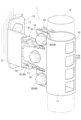
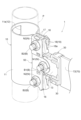
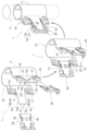
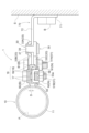
- FIG. 1 Perspective view of pipe fixing structure using pipe support member Perspective view of pipe fixing structure using pipe support member Exploded perspective view of pipe support member Perspective view of fixing auxiliary member and nut holding member Perspective view of nut holding member An exploded perspective view of a fixing auxiliary member and a nut holding member VII-VII cross-sectional view in FIG.
- FIG. 2 is a perspective view seen from the opposite side to FIG.
- the terms “axial direction”, “circumferential direction”, and “radial direction” may be used to express the shape and positional relationship of each member. It is assumed that the pipe P, which is an object to be supported by, is defined as a reference. That is, the “axial direction” represents the axial direction (longitudinal direction) of the pipe P, the “circumferential direction” represents the direction of rotation around the pipe P, and the “radial direction” extends radially from the axial center of the pipe P. represents direction. References to these directions in the description of each part of the pipe support member 1 are intended to indicate the direction in which the pipe P is actually held, unless otherwise specified.
- the pipe support member 1 of the present embodiment is used, for example, in a pipe P arranged from an outdoor unit of an air conditioner installed on the roof of a building such as a building to a plurality of indoor units installed indoors.
- a pipe P for example, a copper refrigerant pipe is exemplified.
- FIG. 1 and 2 show an example of a pipe fixing structure for fixing a predetermined portion of a pipe P arranged in the vertical direction (vertical direction) to a structure S using the pipe support member 1 of the present embodiment. show.
- This pipe fixing structure is used to prevent the pipe P from moving relative to the structure S in the axial direction at the fixed location.
- the structure S is, for example, a building frame, an outer wall, or the like.
- a base metal fitting 70 is fixed to the structure S.
- the base metal fitting 70 may be directly fixed to the structure S, or may be indirectly fixed via another member (for example, an intervening member such as a bracket).
- the base metal fitting 70 is made of metal, and is configured using, for example, a hot-rolled mild steel plate. As shown in FIGS. 1 and 3, the base metal fitting 70 is formed in a bent plate shape.
- the base metal fitting 70 includes a mounting base portion 71 that can be brought into surface contact with the structure S (or an intervening member), and a connecting portion 72 that extends in a state that intersects (perpendicularly in this example) the mounting base portion 71. It has Insertion holes 71a and 72a through which the bolts B are inserted are formed in the mounting base portion 71 and the connecting portion 72, respectively.
- the pipe support member 1 is connected to the base fitting 70 to support the pipe P.
- the pipe support member 1 supports the pipe P arranged along the vertical direction at one point in the axial direction (vertical direction).
- the pipe support member 1 of this embodiment includes a restraining member 10, a fixing auxiliary member 30, and a nut holding member 50.
- the pipe support member 1 includes one restraining member 10 , two fixing auxiliary members 30 and one nut holding member 50 .
- the fixing auxiliary member 30 is detachably attached to the restraining member 10 .
- the nut holding member 50 is detachably attached to the auxiliary fixing member 30 , and is detachably attached to the restraint member 10 via the auxiliary fixing member 30 .
- the restraint member 10 is fixed to the base fitting 70 in a state of surrounding the outer peripheral surface of the pipe P and holding the pipe P.
- the restraint member 10 includes a holding portion 11 , a base fixing portion 13 and a tightening action portion 16 . These are integrally formed.
- the restraining member 10 is made of metal, for example, a hot-rolled mild steel plate.
- the holding part 11 is a part for holding the pipe P.
- the holding portion 11 is formed in a substantially cylindrical shape that is not completely closed.
- the inner diameter of the holding portion 11 is set equal to or substantially equal to the outer diameter of the pipe P.
- the holding portion 11 in the state before use, does not have a shape that follows a perfect circle when viewed in the axial direction, but is expanded to some extent (open posture).
- the holding portion 11 can be attached to the piping P from the radially outer side through this widened frontage.
- the holding part 11 surrounds the outer peripheral surface of the pipe P and holds the pipe P. As shown in FIG.
- the holding portion 11 is formed with a through hole 11a.
- the through hole 11 a is formed in a portion of the holding portion 11 opposite to the base fixing portion 13 and the tightening action portion 16 .
- a plurality of through holes 11a are formed along the axial direction (vertically aligned).
- the through hole 11a functions as a bending strength adjusting portion 12 for adjusting the bending strength of the restraining member 10 (specifically, the holding portion 11 constituting the restraining member 10).
- the base fixing part 13 is a part fixed to the base metal fitting 70 .
- the base fixing portion 13 is composed of a pair of plate portions extending from the holding portion 11 so as to face each other. In this embodiment, a pair of plate portions constituting the base fixing portion 13 extend radially from both circumferential ends of the substantially cylindrical holding portion 11 that is not completely closed.
- the base fixing portion 13 is formed in an elongated rectangular shape.
- the base fixing portion 13 is formed with an insertion hole 13a through which a bolt B (specifically, a first bolt B1) is inserted.
- the base fixing portion 13 is fixed to the base metal fitting 70 by fastening the first bolt B1.
- the shaft portion of the first bolt B1 is inserted through the two insertion holes 13a of the base fixing portion 13 and the insertion hole 72a of the base metal fitting 70, and is screwed to the nut N (specifically, the first nut N1) on the opposite side.
- the base fixing portion 13 is fixed to the base metal fitting 70 by being tightened.
- locking recesses 14 recessed toward the center line side of the base fixing portion 13 are formed in the upper and lower side edges 13b of the pair of plate portions constituting the base fixing portion 13, respectively.
- the locking claw portion 35 of the fixing auxiliary member 30 is locked to the locking concave portion 14 .
- the tightening action part 16 is a part for applying a tightening force to the holding part 11 .
- the tightening action portion 16 is composed of a pair of plate portions extending from the holding portion 11 so as to face each other.
- a pair of plate portions constituting the tightening action portion 16 extends radially from both circumferential ends of the substantially cylindrical holding portion 11 that is not completely closed.
- the extension length of the tightening action portion 16 from the holding portion 11 is shorter than the extension length of the base fixing portion 13 .
- the two tightening action portions 16 are vertically separated with the base fixing portion 13 interposed therebetween.
- the tightening action portion 16 has a tightening main body portion 17 and a tip bent portion 18 .
- the tightening body portion 17 is the main portion of the tightening action portion 16 .
- the fastening main body portion 17 is formed in a substantially trapezoidal shape.
- the two upper and lower tightening main body portions 17 (the tightening main body portion 17 positioned on the front side in FIG. 8) extending from one end in the circumferential direction of the holding portion 11 are both located on the upper side rather than the lower base. It is formed in an inverted trapezoid shape with the longer side.
- the two upper and lower tightening body portions 17 (the tightening body portion 17 located on the far side in FIG.
- a raised portion 17B that protrudes outward is formed in the central portion of the tightening main body portion 17 .
- the raised portion 17B is formed in a circular shape.
- the raised portion 17B functions as a circular rib to improve the strength of the tightening body portion 17.
- An insertion hole 17a through which a bolt B (specifically, a second bolt B2 different from the first bolt B1) is inserted is formed in the central portion of the raised portion 17B.
- the tightening main body portion 17 including the raised portion 17B is a portion of the tightening action portion 16 to which the second bolt B2 is tightened.
- the second bolt B2 is fastened at a position closer to the holding portion 11 than the first bolt B1.
- the shaft portion of the second bolt B2 is inserted through the insertion hole 17a of the tightening main body portion 17, and the nut N (specifically, the second nut N2) is screwed and fastened on the opposite side, so that the holding portion A clamping force can be applied to 11 .
- maintenance part 11 can be raised, and the piping P can be supported appropriately.
- welding such as brazing is not required, and work can be performed only by tightening the bolts B (the first bolt B1 and the second bolt B2), resulting in good work efficiency.
- Bolt operation can also be performed with an electric drill, in which case work efficiency can be greatly improved.
- the pipe P is held by the surface pressure of the holding portion 11, the pipe P is not oxidized or deformed (for example, a recess due to bite), and the reliability is high.
- the tip bent portion 18 is a portion obtained by bending the tip portion of the tightening main body portion 17 opposite to the holding portion 11 .
- the tip bent portion 18 is bent substantially perpendicularly to the tightening main body portion 17 .
- tip bending portions 18 are bent so as to face each other.
- the two tip bent portions 18 facing each other are in contact with each other while crossing each other.
- the distal bent portion 18 has a substantially rectangular notch recess 18a in its vertical central region.
- the bent distal end portions 18 of the pair of opposing tightening action portions 16 cross and abut each other with their notch recesses 18a facing each other.
- the tip bending portion 18 is provided on the side opposite to the holding portion 11 with respect to the tightening position of the second bolt B2 in the tightening main body portion 17 (that is, the position of the insertion hole 17a). They abut each other when tightened by the bolt B2. Due to this abutment, the tip bent portion 18 acts to maintain a constant distance between the tightening body portions 17 when tightened by the second bolt B2. As a result, when the second bolt B2 is tightened, the points of contact between the tip bent portions 18 serve as fulcrums, and the tightening main body portions 17 facing each other at a certain distance can be held more firmly. , a larger tightening force can be applied to the holding portion 11 . In this way, the surface pressure of the inner surface of the holding portion 11 can be further increased, and the pipe P can be firmly supported.
- the tightening force due to the tightening of the second bolt B2 can be uniformly applied to the pair of tightening action portions 16 .
- the strength of the tightening main body portion 17 itself is increased by forming the circular raised portion 17B, and together with this, the tightening action portion 16 is stabilized in a state where there is almost no deformation or deviation.
- the piping P can be supported effectively.
- the tip bent portions 18 function as the proximity restricting portions 19 that contact each other when tightened by the second bolt B2 to maintain a constant distance between the tightening main body portions 17 .
- cutout portions 21 are provided between the base fixing portion 13 and the two tightening action portions 16, respectively.
- the notch 21 is formed continuously from the upper and lower side edges 13b of the base fixing portion 13 and extends in the radial direction.
- the pipe support member 1 of this embodiment includes a fixing auxiliary member 30 that is detachable from the restraining member 10.
- the fixing assisting member 30 includes a main body portion 31, an attached portion 32, a side wall portion 33, a pressing piece 34, a locking claw portion 35, a first extending portion 36, an engaged portion 37, and a second It has two extensions 38 and engaging claws 39 . These are integrally formed.
- the fixation assisting member 30 is made of resin, such as polypropylene or polyacetal.
- the body portion 31 is formed in a flat plate shape along the base fixing portion 13 of the restraining member 10 . Further, the body portion 31 is formed in a rectangular shape. The body portion 31 is formed with an insertion hole 31a through which a bolt B (specifically, a first bolt B1) is inserted. The body portion 31 is in a state in which the auxiliary fixing member 30 is attached to the restraining member 10 (hereinafter, simply referred to as the “attached state”), along the inner surfaces of the pair of plates constituting the base fixing portion 13 . placed.
- the side wall portion 33 is formed along three sides of the rectangular main body portion 31 so as to rise vertically from the main body portion 31 .
- the side wall portion 33 has a first portion 33A, and a second portion 33B and a third portion 33C extending from both ends of the first portion 33A.
- 33 A of 1st parts contact
- the second portion 33B and the third portion 33C abut on the upper and lower side edges 13b of the base fixing portion 13 in the attached state.
- the pressing piece 34 is formed at the boundary between the first portion 33A and the second portion 33B of the side wall portion 33 and the boundary between the first portion 33A and the third portion 33C.
- the pressing piece 34 is formed in an L shape at a position separated from the body portion 31 by the plate thickness of the base fixing portion 13 of the restraining member 10 .
- the pressing piece 34 abuts on the outer surface of each of the pair of plate members that constitute the base fixing portion 13 in the attached state. As a result, in the attached state, the main body portion 31 and the pressing piece 34 cooperate to press the pair of plate members forming the base fixing portion 13 from both the inner and outer sides.
- the locking claw portion 35 is formed so as to extend continuously from the second portion 33B and the third portion 33C of the side wall portion 33 .
- the locking claws 35 are locked to the locking recesses 14 formed in the upper and lower side edges 13b of the pair of plate portions forming the base fixing portion 13 in the attached state (see FIG. 8).
- the locking recess 14 of the base fixing portion 13 and the locking claw portion 35 of the auxiliary fixing member 30 cooperate to prevent the auxiliary fixing member 30 attached to the restraining member 10 from coming off. It functions as part 41 .
- the attached portion 32 is formed on a side portion of the body portion 31 where the side wall portion 33 is not provided (in other words, the opposite side of the side portion provided with the first portion 33A).
- a pair of attached portions 32 are formed so as to protrude upward and downward from both upper and lower end portions of a side portion of the body portion 31 opposite to the first portion 33A.
- the attached portion 32 is provided adjacent to the locking claw portion 35 .
- the attached portion 32 is arranged in the notch portion 21 in a state in which the auxiliary fixing member 30 is attached to the restraining member 10 .
- a holding attachment portion 54 provided on the nut holding member 50 is attached to the attached portion 32 .
- the first extending portion 36 extends outward from the second portion 33B of the side wall portion 33 .
- the second extending portion 38 extends outward from the third portion 33C of the side wall portion 33 .
- the direction in which the first extension portion 36 extends and the direction in which the second extension portion 38 extends are opposite to each other.
- the engaged portion 37 is provided at the tip of the first extension portion 36 so as to intersect (perpendicularly in this example) the first extension portion 36 .
- the engaging claw portion 39 is provided at the tip portion of the second extension portion 38 so as to intersect (perpendicularly in this example) the second extension portion 38 .
- the extending direction of the engaged portion 37 and the extending direction of the engaging claw portion 39 are opposite to each other.
- the fixing auxiliary members 30 having the same shape are attached to the pair of plate bodies that constitute the base fixing portion 13, respectively.
- the engaging claw portion 39 of one auxiliary fixing member 30 is engaged with the engaged portion 37 of the other auxiliary fixing member 30 as shown in FIGS.
- the engaged portion 37 of one auxiliary fixing member 30 is engaged with the engaging claw portion 39 of the other auxiliary fixing member 30 .
- the restraint member 10 is kept in the closed posture even if the operator releases the hand.
- the engaged portion 37 and the engaging claw portion 39 provided separately on the two fixing assisting members 30 cooperate to form the closed posture holding portion 42 that holds the closed posture of the restraint member 10. Function.
- the auxiliary fixing member 30 is firstly used to temporarily fix the base fixing portion 13 to the base metal fitting 70 before fastening with the first bolt B1. Therefore, the operator can perform the fastening operation with the first bolt B1 with both hands free, which is excellent in workability.
- the auxiliary fixing member 30 is maintained in the mounted state even after the first bolt B1 is tightened, and the connecting portion 72 of the base metal fitting 70 and the pair of plate bodies constituting the base fixing portions 13 on both sides thereof are connected.
- the main body portion 31 of the fixing auxiliary member 30 is interposed between them.
- the auxiliary fixing member 30 is used as a spacer to prevent the base fitting 70 and the base fixing portion 13 from coming into direct contact with each other.
- the auxiliary fixing member 30 interposed between the base metal fitting 70 and the base fixing portion 13 is made of a resin having a low thermal conductivity, heat transfer from the base fixing portion 13 to the base metal fitting 70 is reduced. greatly suppressed.
- the auxiliary fixing member 30 is used as a heat insulating material that suppresses heat transfer from the base fixing portion 13 to the base metal fitting 70 .
- the pipe P is a refrigerant pipe as in the present embodiment
- the heat (for example, cold heat) of the refrigerant flowing through the pipe P can be transferred to the metal restraining member 10 via the pipe P.
- the auxiliary fixing member 30 functions as a heat insulating material and can suppress the transfer of the cold heat to the base metal fitting 70 . As a result, dew condensation on the surface of the base metal fitting 70 can be suppressed.
- the nut holding member 50 holds the first nut N1 and the second nut N2, and the first nut N1 and the second nut N2 are arranged at their respective mounting positions. It is detachably attached to the restraint member 10 as shown in FIG.
- the nut holding member 50 holds one first nut N1 and two second nuts N2.
- the mounting position of the first nut N1 is a position that overlaps with the insertion hole 13a of the base fixing portion 13, and the mounting position of the second nut N2 is the two upper and lower tightening action portions 16 (specifically, tightening action portions 16). It is the position which respectively overlaps with the insertion hole 17a of the main-body part 17).
- the nut holding member 50 is detachably attached to the auxiliary fixing member 30 attached to the restraining member 10 . That is, the nut holding member 50 is indirectly attached to the restraining member 10 via the fixing auxiliary member 30 .
- the nut holding member 50 has a holding body portion 51, a holding mounting portion 54, and a holding engaging portion 56. As shown in FIGS. These are integrally formed.
- the nut holding member 50 is made of resin such as polypropylene or polyacetal.
- the holding body portion 51 is a main portion that holds the first nut N1 and the second nut N2.
- the holding body portion 51 has a central plate portion 51A and a pair of extending plate portions 51B extending from the central plate portion 51A to both upper and lower sides. These are integrally formed.
- the extending plate portion 51B is formed offset from the central plate portion 51A so as to be spaced apart from the restraining member 10 when attached to the restraining member 10 .
- the extending plate portion 51B is offset from the central plate portion 51A by an amount corresponding to the raised height of the raised portion 17B formed on the fastening body portion 17 of the fastening action portion 16 .
- a first holding insertion hole 52 is formed through the holding body portion 51 .
- One first holding insertion hole 52 is formed in the center plate portion 51A of the holding main body portion 51 .
- the holding body portion 51 holds the first nut N ⁇ b>1 while being inserted into the first holding insertion hole 52 .
- a flanged nut is used as the first nut N1.
- the first nut N1 is held while being locked to the peripheral edge of the hole 52 .
- the first holding insertion hole 52 is formed in a substantially hexagonal shape corresponding to the outer shape of the nut body of the first nut N1. Therefore, the holding main body portion 51 can hold the first nut N1 in a non-rotating state.
- the first holding insertion hole 52 is formed by partially cutting out the circumferential direction with a slit-shaped cutout portion 52a. Due to the presence of this slit-shaped notch 52a, the rotation of the first nut N1 is not completely prevented by the first holding insertion hole 52, and the rotation of the first nut N1 is allowed when a large force acts. It has become.
- a second holding insertion hole 53 is formed through the holding body portion 51 .
- the second holding insertion hole 53 is formed in each of the pair of extending plate portions 51B of the holding main body portion 51 .
- the holding main body portion 51 holds the second nut N2 while being inserted into the second holding insertion hole 53 .
- a flanged nut is used as the second nut N2.
- the second nut N2 is held while being locked to the peripheral edge of the hole 53 .
- the second holding insertion hole 53 is formed in a substantially hexagonal shape corresponding to the outer shape of the nut body of the second nut N2. Therefore, the holding main body portion 51 can hold the second nut N2 in a non-rotating state.
- the second holding insertion hole 53 is formed by partially cutting out the circumferential direction with a slit-shaped cutout portion 53a. Due to the presence of this slit-shaped notch 53a, the rotation of the second nut N2 is not completely prevented by the second holding insertion hole 53, and the rotation of the second nut N2 is allowed when a large force acts. It has become.
- the holding attachment portion 54 is erected from the holding body portion 51 (specifically, the extension plate portion 51B).
- the holding attachment portion 54 is provided at a position between the first holding insertion hole 52 and the second holding insertion hole 53 .
- the holding attachment portion 54 is composed of a pair of claw portions, and is attached to the attached portion 32 provided on the auxiliary fixing member 30.
- the holding attachment portion 54 is attached to the attached portion 32 at the position of the notch portion 21 provided in the restraining member 10 in a state where the fixing auxiliary member 30 is attached to the restraining member 10 .
- the nut holding member 50 is indirectly attached to the base fixing portion 13 via the fixing auxiliary member 30 at the position of the notch portion 21 .
- the holding engagement portion 56 is provided at the tip of the holding body portion 51 (specifically, the extension plate portion 51B).
- the holding engagement portion 56 is provided across a pair of leg portions 55 that are bent at the distal end portion of the holding main body portion 51 .
- the holding engaging portion 56 is composed of a triangular engaging piece directed downward. As shown in FIGS. 1, 2, and 10, the holding engaging portion 56 is attached to the tightening action portion 16 in a state in which the nut holding member 50 is attached to the restraining member 10 via the fixing auxiliary member 30. are engaged from the side opposite to the holding body portion 51 . This stabilizes the mounting posture of the nut holding member 50 and the holding posture of the first nut N1 and the second nut N2.
- the pipe support member 1 of this embodiment is detachably attached to the restraining member 10 while the nut holding member 50 holds the first nut N1 and the second nut N2.
- the nut holding member 50 holds the first nut N1 and the second nut N2 in their respective mounting positions before tightening. , N2 need not be held by hand.
- the operator since the first nut N1 is prevented from rotating by the first holding insertion hole 52 and the second nut N2 is prevented from rotating by the second holding insertion hole 53, the operator only needs to tighten the first bolt B1 and the second bolt B2. can be operated to perform fastening work, and work efficiency can be greatly improved.
- the first holding insertion hole 52 and the second holding insertion hole 53 are formed by partially cutting out the circumferential direction, the first bolt B1 and the second bolt B2 can be fastened with a large force using, for example, a tool.
- the rotation of the first nut N1 and the second nut N2 can be allowed, and they can be firmly fastened. Therefore, the restraining member 10 can be firmly fixed to the base metal fitting 70, and a large tightening force can be applied to the holding portion 11 to increase the surface pressure of the inner surface of the holding portion 11 to appropriately support the pipe P. can be done.
- the configuration in which the first holding insertion hole 52 and the second holding insertion hole 53 are formed in a substantially hexagonal shape with a part notched in the circumferential direction has been described as an example.
- at least one of the first holding insertion hole 52 and the second holding insertion hole 53 may be formed in a substantially closed hexagonal shape without a notch.
- the first holding through-hole 52 and the second holding through-hole 53 may be formed in other shapes such as ovals, as long as they can prevent rotation of at least the first nut N1 and the second nut N2.
- the first holding insertion hole 52 and the second holding insertion hole 53 may be formed in perfect circles, and do not necessarily have the function of preventing rotation of the first nut N1 and the second nut N2.
- the configuration in which the nut holding member 50 is attached to the base fixing portion 13 in the notch portion 21 via the fixing auxiliary member 30 has been described as an example.
- the nut holding member 50 may be attached to the tightening action portion 16 within the notch portion 21 .
- the nut holding member 50 may be attached to the base fixing portion 13 via the fixing auxiliary member 30 outside the notch portion 21 .
- the configuration in which the nut holding member 50 is provided with the holding engagement portion 56 that engages the tightening action portion 16 from the side opposite to the holding main body portion 51 has been described as an example.
- the nut holding member 50 may be attached to the restraining member 10 only by the holding attachment portion 54 without such a holding engagement portion 56 .
- the piping support member 1 includes the auxiliary fixing member 30, and the nut holding member 50 is indirectly attached to the restraining member 10 via the auxiliary fixing member 30, as an example.
- the nut holding member can 50 may be attached directly to the restraining member 10 .
- the nut holding member 50 is used together with the restraining member 10 fixed to the base fitting 70 in a state where the pipe support member 1 surrounds the outer peripheral surface of the pipe P and holds the pipe P.
- the configuration has been described as an example. However, without being limited to such a configuration, the nut retaining member 50 can also be used with any member that is fixed by tightening a bolt B and a nut N threaded thereon. A nut retaining member 50 of such non-limiting application is also disclosed hereby.
- the nut holding member 50 in this case is A nut holder that is detachably attached to a member to be fixed that is fixed by fastening a bolt B and a nut N screwed thereto so that the nut N is arranged at a mounting position while holding the nut N. member 50, and the configuration.
Landscapes
- Engineering & Computer Science (AREA)
- General Engineering & Computer Science (AREA)
- Mechanical Engineering (AREA)
- Supports For Pipes And Cables (AREA)
- Clamps And Clips (AREA)
Priority Applications (4)
| Application Number | Priority Date | Filing Date | Title |
|---|---|---|---|
| JP2023562116A JP7561288B2 (ja) | 2021-11-19 | 2022-06-10 | 配管支持部材 |
| US18/711,235 US12565946B2 (en) | 2021-11-19 | 2022-06-10 | Pipe support member |
| EP22895143.0A EP4428381A4 (en) | 2021-11-19 | 2022-06-10 | TUBE SUPPORT ELEMENT |
| JP2024135275A JP2024149782A (ja) | 2021-11-19 | 2024-08-14 | 配管支持部材 |
Applications Claiming Priority (2)
| Application Number | Priority Date | Filing Date | Title |
|---|---|---|---|
| JP2021188611 | 2021-11-19 | ||
| JP2021-188611 | 2021-11-19 |
Publications (1)
| Publication Number | Publication Date |
|---|---|
| WO2023089854A1 true WO2023089854A1 (ja) | 2023-05-25 |
Family
ID=86396539
Family Applications (2)
| Application Number | Title | Priority Date | Filing Date |
|---|---|---|---|
| PCT/JP2022/023440 Ceased WO2023089854A1 (ja) | 2021-11-19 | 2022-06-10 | 配管支持部材 |
| PCT/JP2022/023439 Ceased WO2023089853A1 (ja) | 2021-11-19 | 2022-06-10 | 配管支持部材 |
Family Applications After (1)
| Application Number | Title | Priority Date | Filing Date |
|---|---|---|---|
| PCT/JP2022/023439 Ceased WO2023089853A1 (ja) | 2021-11-19 | 2022-06-10 | 配管支持部材 |
Country Status (4)
| Country | Link |
|---|---|
| US (2) | US12546415B2 (https=) |
| EP (2) | EP4428378A4 (https=) |
| JP (6) | JP7587060B2 (https=) |
| WO (2) | WO2023089854A1 (https=) |
Families Citing this family (1)
| Publication number | Priority date | Publication date | Assignee | Title |
|---|---|---|---|---|
| USD1065964S1 (en) * | 2023-01-31 | 2025-03-11 | Inaba Denki Sangyo Co., Ltd. | Piping support tool |
Citations (11)
| Publication number | Priority date | Publication date | Assignee | Title |
|---|---|---|---|---|
| JPH1078018A (ja) * | 1996-09-05 | 1998-03-24 | Sugiura Seisakusho:Kk | 脱落防止用キャップ及びこれを含む脱落防止雌ねじ部材 |
| JP2002147426A (ja) * | 2000-11-07 | 2002-05-22 | Nakai Kogyo Kk | ナット保持構造及びボルト保持構造 |
| JP2003148435A (ja) * | 2001-11-12 | 2003-05-21 | Ihara Kogyo:Kk | ボルト締結具 |
| JP2004232798A (ja) * | 2003-01-31 | 2004-08-19 | Otis:Kk | パイプ支持バンドの仮止め具 |
| JP2005003014A (ja) * | 2003-06-09 | 2005-01-06 | Akagi:Kk | 配管支持具用伴回り防止方法及び防止具 |
| JP2010276180A (ja) * | 2009-06-01 | 2010-12-09 | Sekisui Chem Co Ltd | 裏ナット金物及び裏ナット付被取付物 |
| WO2012079126A1 (en) * | 2010-12-15 | 2012-06-21 | Pro 3 Products Pty Ltd | System and components for safely enclosing handrails, stairways, walkways and platforms |
| CN205350566U (zh) * | 2016-01-19 | 2016-06-29 | 乐清市华顿电子有限公司 | 排气管用卡箍 |
| JP2016169840A (ja) * | 2015-03-13 | 2016-09-23 | 周 加藤 | ナット |
| JP2017057969A (ja) * | 2015-09-18 | 2017-03-23 | 積水化学工業株式会社 | 配管支持構造 |
| JP2018025290A (ja) | 2016-08-08 | 2018-02-15 | 因幡電機産業株式会社 | 配管用装着部材 |
Family Cites Families (50)
| Publication number | Priority date | Publication date | Assignee | Title |
|---|---|---|---|---|
| US624484A (en) * | 1899-05-09 | Hanger for supporting small metallic pipes | ||
| US628743A (en) * | 1897-12-28 | 1899-07-11 | William W Tucker | Clamping attachment for saddles. |
| US693861A (en) * | 1901-10-16 | 1902-02-25 | Charles C Redding | Wrench. |
| US2193758A (en) * | 1937-09-10 | 1940-03-12 | Bentley Bede John Francis | Means for securing rain water pipes to walls |
| US2252072A (en) * | 1939-08-16 | 1941-08-12 | Electric Household Utilities | Fluid discharge apparatus for laundry machines |
| US2352823A (en) * | 1941-02-03 | 1944-07-04 | Adel Prec Products Corp | Universal support for conduits |
| USRE22673E (en) * | 1941-12-03 | 1945-09-11 | Fastening means | |
| US2338658A (en) * | 1942-09-21 | 1944-01-04 | Adel Prec Products Corp | Temporary holding device for conduit clips |
| US2407609A (en) * | 1942-11-28 | 1946-09-10 | Tinnerman Products Inc | Fastening device |
| US2421443A (en) * | 1943-07-13 | 1947-06-03 | Carel T Torresen | Clamp |
| US2464620A (en) * | 1944-06-19 | 1949-03-15 | Tinnerman Products Inc | Fastening device |
| US2826385A (en) * | 1955-01-31 | 1958-03-11 | Irving Gaynor | Pipe-supporting clamp |
| US3068924A (en) * | 1958-04-18 | 1962-12-18 | Gen Motors Corp | Nut assembly |
| US2998217A (en) * | 1959-07-06 | 1961-08-29 | T A Mfg Corp | Quick-opening line supporting clamp |
| US3099054A (en) * | 1961-04-24 | 1963-07-30 | Lockheed Aircraft Corp | Flexible multi-purpose clamp |
| US3258822A (en) * | 1963-01-28 | 1966-07-05 | Continental Ind Inc | Pipe clamp |
| US3815855A (en) * | 1972-08-10 | 1974-06-11 | A Appleton | Integral clamp and clamp-back for electrical conduit |
| US4029276A (en) * | 1972-08-21 | 1977-06-14 | Caterpillar Tractor Co. | Mounting bracket for tubular members |
| US4113286A (en) * | 1976-09-17 | 1978-09-12 | United States Pipe And Foundry Company | Hanger for pipe |
| US4153228A (en) * | 1977-10-03 | 1979-05-08 | General Electric Company | Self-tightening clamp |
| NL8900619A (nl) * | 1989-03-14 | 1990-10-01 | Walraven J Van Bv | Buisklem. |
| JP2529038Y2 (ja) * | 1990-08-15 | 1997-03-12 | カヤバ工業株式会社 | ナックルブラケット |
| US5893538A (en) * | 1991-09-13 | 1999-04-13 | Onishi; Yoshio | Conduit clamp |
| US5738326A (en) * | 1996-10-16 | 1998-04-14 | Hwa Shin Musical Instrument Co. Ltd. | Seat stem positioning structure of a chair for drummer |
| JP3272290B2 (ja) * | 1997-12-12 | 2002-04-08 | 日栄インテック株式会社 | ボルト付配管バンド |
| US5927810A (en) * | 1998-07-23 | 1999-07-27 | Hwa Hsin Musical Instrument Co., Ltd. | Adjustable musician's chair |
| JP2001324058A (ja) * | 2000-05-17 | 2001-11-22 | Hiroshi Miyazaki | 配管支持金具 |
| US6672545B1 (en) * | 2000-11-07 | 2004-01-06 | Erico International Corporation | Device for resisting movement of a suspended pipe |
| US6443402B1 (en) * | 2000-12-01 | 2002-09-03 | Commscope Properties, Llc | Cable hanger |
| US6557878B2 (en) * | 2001-02-22 | 2003-05-06 | Giant Manufacturing Co., Ltd. | Locking device for releasably locking a seat post relative to a seat tube of a bicycle frame |
| JP2003021125A (ja) * | 2001-07-05 | 2003-01-24 | Tadao Ishida | 継ぎボルト |
| NL1020580C2 (nl) | 2002-05-13 | 2003-11-14 | Walraven J Van Bv | Beugel. |
| JP4805630B2 (ja) | 2005-08-04 | 2011-11-02 | 矢崎総業株式会社 | 表示装置 |
| ITPD20050248A1 (it) * | 2005-08-05 | 2007-02-06 | Moretto P A Srl | Dispositivo di fissaggio di tubazioni a strutture portanti |
| JP4724027B2 (ja) * | 2006-03-23 | 2011-07-13 | 因幡電機産業株式会社 | 空調用縦配管の固定支持装置 |
| JP2008053014A (ja) | 2006-08-23 | 2008-03-06 | Orc Mfg Co Ltd | 光照射装置 |
| GB201009967D0 (en) * | 2010-06-15 | 2010-07-21 | Airbus Operations Ltd | Conduit harness |
| DE102011009536B4 (de) * | 2011-01-27 | 2013-09-19 | Norma Germany Gmbh | Spannschelle |
| WO2012117827A1 (ja) * | 2011-02-28 | 2012-09-07 | 本田技研工業株式会社 | ナット付きブラケット |
| NL2011194C2 (en) * | 2013-07-18 | 2015-01-21 | Walraven Holding Bv J Van | Pipe clip with locking feature. |
| US20150252941A1 (en) * | 2014-03-06 | 2015-09-10 | Satellite Metal Inc. | Post connecting bracket for ornamental fences |
| DE102014106656A1 (de) * | 2014-05-12 | 2015-11-26 | Salzgitter Mannesmann Stahlhandel Gmbh | Spannvorrichtung zum Verbinden von Profilschienen |
| WO2018058120A1 (en) * | 2016-09-26 | 2018-03-29 | Norma U.S. Holding Llc | Band clamp for overlapping pipe ends |
| FR3057332B1 (fr) * | 2016-10-11 | 2019-04-05 | Akwel Vannes France | Procede de fixation d’un conduit sur un support au moyen de brides captives librement ajustables |
| KR101998120B1 (ko) | 2017-04-17 | 2019-07-09 | 주식회사 메이크순 | 수평 배관 4방향 버팀장치 |
| KR102557404B1 (ko) * | 2017-05-31 | 2023-07-19 | 삼성전자주식회사 | 세탁기 |
| JP2019203582A (ja) | 2018-05-25 | 2019-11-28 | エヌパット株式会社 | 縦配管用支持金具 |
| US11560969B2 (en) | 2019-09-17 | 2023-01-24 | ASC Engineered Solutions, LLC | Pipe hanger with lock tab washer |
| US11067202B2 (en) * | 2019-12-19 | 2021-07-20 | GM Global Technology Operations LLC | Puzzle-lock pipe mount assembly |
| US11006588B1 (en) * | 2020-04-29 | 2021-05-18 | Terry B. Jordan | Hillside agricultural irrigation apparatus |
-
2022
- 2022-06-10 JP JP2023562115A patent/JP7587060B2/ja active Active
- 2022-06-10 US US18/711,160 patent/US12546415B2/en active Active
- 2022-06-10 EP EP22895142.2A patent/EP4428378A4/en active Pending
- 2022-06-10 US US18/711,235 patent/US12565946B2/en active Active
- 2022-06-10 WO PCT/JP2022/023440 patent/WO2023089854A1/ja not_active Ceased
- 2022-06-10 WO PCT/JP2022/023439 patent/WO2023089853A1/ja not_active Ceased
- 2022-06-10 JP JP2023562116A patent/JP7561288B2/ja active Active
- 2022-06-10 EP EP22895143.0A patent/EP4428381A4/en active Pending
-
2024
- 2024-08-14 JP JP2024135275A patent/JP2024149782A/ja active Pending
- 2024-08-14 JP JP2024135274A patent/JP2024149781A/ja active Pending
-
2025
- 2025-10-01 JP JP2025165445A patent/JP7777258B1/ja active Active
- 2025-11-12 JP JP2025192624A patent/JP7784023B1/ja active Active
Patent Citations (11)
| Publication number | Priority date | Publication date | Assignee | Title |
|---|---|---|---|---|
| JPH1078018A (ja) * | 1996-09-05 | 1998-03-24 | Sugiura Seisakusho:Kk | 脱落防止用キャップ及びこれを含む脱落防止雌ねじ部材 |
| JP2002147426A (ja) * | 2000-11-07 | 2002-05-22 | Nakai Kogyo Kk | ナット保持構造及びボルト保持構造 |
| JP2003148435A (ja) * | 2001-11-12 | 2003-05-21 | Ihara Kogyo:Kk | ボルト締結具 |
| JP2004232798A (ja) * | 2003-01-31 | 2004-08-19 | Otis:Kk | パイプ支持バンドの仮止め具 |
| JP2005003014A (ja) * | 2003-06-09 | 2005-01-06 | Akagi:Kk | 配管支持具用伴回り防止方法及び防止具 |
| JP2010276180A (ja) * | 2009-06-01 | 2010-12-09 | Sekisui Chem Co Ltd | 裏ナット金物及び裏ナット付被取付物 |
| WO2012079126A1 (en) * | 2010-12-15 | 2012-06-21 | Pro 3 Products Pty Ltd | System and components for safely enclosing handrails, stairways, walkways and platforms |
| JP2016169840A (ja) * | 2015-03-13 | 2016-09-23 | 周 加藤 | ナット |
| JP2017057969A (ja) * | 2015-09-18 | 2017-03-23 | 積水化学工業株式会社 | 配管支持構造 |
| CN205350566U (zh) * | 2016-01-19 | 2016-06-29 | 乐清市华顿电子有限公司 | 排气管用卡箍 |
| JP2018025290A (ja) | 2016-08-08 | 2018-02-15 | 因幡電機産業株式会社 | 配管用装着部材 |
Non-Patent Citations (1)
| Title |
|---|
| See also references of EP4428381A4 |
Also Published As
| Publication number | Publication date |
|---|---|
| US12546415B2 (en) | 2026-02-10 |
| EP4428381A4 (en) | 2025-11-12 |
| EP4428381A1 (en) | 2024-09-11 |
| JP7561288B2 (ja) | 2024-10-03 |
| JPWO2023089853A1 (https=) | 2023-05-25 |
| WO2023089853A1 (ja) | 2023-05-25 |
| JP2025178447A (ja) | 2025-12-05 |
| US20250003529A1 (en) | 2025-01-02 |
| EP4428378A4 (en) | 2025-11-12 |
| JP7784023B1 (ja) | 2025-12-10 |
| JP7587060B2 (ja) | 2024-11-19 |
| JP2024149782A (ja) | 2024-10-18 |
| US12565946B2 (en) | 2026-03-03 |
| JPWO2023089854A1 (https=) | 2023-05-25 |
| JP2026012496A (ja) | 2026-01-23 |
| EP4428378A1 (en) | 2024-09-11 |
| JP2024149781A (ja) | 2024-10-18 |
| JP7777258B1 (ja) | 2025-11-27 |
| US20250003528A1 (en) | 2025-01-02 |
Similar Documents
| Publication | Publication Date | Title |
|---|---|---|
| JP7784023B1 (ja) | 配管支持部材 | |
| JP2020516835A (ja) | 水平配管4方向支え装置 | |
| US8206070B2 (en) | Weld adapter | |
| JP2011196404A (ja) | 縦配管固定構造及びそれに用いられる取付け基材 | |
| JP2004019688A (ja) | 空調用縦配管の固定支持装置 | |
| JP6156903B2 (ja) | 配管の留め具構造 | |
| JP2009161938A (ja) | ねじ締め機構及びこのねじ締め機構を用いた建築用仮組金具 | |
| JP2007255591A (ja) | 空調用縦配管の固定支持装置 | |
| JP4148684B2 (ja) | 配管用クランプ金具 | |
| JP5912481B2 (ja) | 建築用取付具 | |
| JP6108268B2 (ja) | 外装改修用治具及び外装改修構造 | |
| JP2003207172A (ja) | 空調用縦配管の固定支持装置 | |
| JP5324989B2 (ja) | 配管ダクト用固定具 | |
| JP2005240900A (ja) | 配管用uボルト | |
| JP2019203582A (ja) | 縦配管用支持金具 | |
| JP2024129392A (ja) | 配管固定装置及び配管固定方法 | |
| JP2520256Y2 (ja) | 養生クランプ | |
| KR20240141542A (ko) | 배관클램프용 커넥터 및 이를 이용한 배관지지유닛 | |
| JP4695161B2 (ja) | 配管支持金具の取付具 | |
| JP2004125191A (ja) | 連結ダクトとそのパーツ | |
| JP2014190505A (ja) | 締結部位絶縁具、熱交換器及び室外機 | |
| JP5480014B2 (ja) | 床構造及び固定具 | |
| JP3004271U (ja) | 銅管固定金具 | |
| JP2006070486A (ja) | 足場板支持用ブラケット | |
| JPH0723891U (ja) | 配管保護ダクトの接続装置 |
Legal Events
| Date | Code | Title | Description |
|---|---|---|---|
| 121 | Ep: the epo has been informed by wipo that ep was designated in this application |
Ref document number: 22895143 Country of ref document: EP Kind code of ref document: A1 |
|
| ENP | Entry into the national phase |
Ref document number: 2023562116 Country of ref document: JP Kind code of ref document: A |
|
| WWE | Wipo information: entry into national phase |
Ref document number: 18711235 Country of ref document: US |
|
| WWE | Wipo information: entry into national phase |
Ref document number: 2022895143 Country of ref document: EP |
|
| ENP | Entry into the national phase |
Ref document number: 2022895143 Country of ref document: EP Effective date: 20240604 |
|
| NENP | Non-entry into the national phase |
Ref country code: DE |
|
| WWG | Wipo information: grant in national office |
Ref document number: 18711235 Country of ref document: US |