WO2023084726A1 - 電力変換装置及び冷凍サイクル適用機器 - Google Patents
電力変換装置及び冷凍サイクル適用機器 Download PDFInfo
- Publication number
- WO2023084726A1 WO2023084726A1 PCT/JP2021/041676 JP2021041676W WO2023084726A1 WO 2023084726 A1 WO2023084726 A1 WO 2023084726A1 JP 2021041676 W JP2021041676 W JP 2021041676W WO 2023084726 A1 WO2023084726 A1 WO 2023084726A1
- Authority
- WO
- WIPO (PCT)
- Prior art keywords
- current
- inverter
- capacitor
- power
- power converter
- Prior art date
- Legal status (The legal status is an assumption and is not a legal conclusion. Google has not performed a legal analysis and makes no representation as to the accuracy of the status listed.)
- Ceased
Links
Images



Classifications
-
- H—ELECTRICITY
- H02—GENERATION; CONVERSION OR DISTRIBUTION OF ELECTRIC POWER
- H02M—APPARATUS FOR CONVERSION BETWEEN AC AND AC, BETWEEN AC AND DC, OR BETWEEN DC AND DC, AND FOR USE WITH MAINS OR SIMILAR POWER SUPPLY SYSTEMS; CONVERSION OF DC OR AC INPUT POWER INTO SURGE OUTPUT POWER; CONTROL OR REGULATION THEREOF
- H02M3/00—Conversion of DC power input into DC power output
- H02M3/003—Constructional details, e.g. physical layout, assembly, wiring or busbar connections
-
- F—MECHANICAL ENGINEERING; LIGHTING; HEATING; WEAPONS; BLASTING
- F25—REFRIGERATION OR COOLING; COMBINED HEATING AND REFRIGERATION SYSTEMS; HEAT PUMP SYSTEMS; MANUFACTURE OR STORAGE OF ICE; LIQUEFACTION SOLIDIFICATION OF GASES
- F25B—REFRIGERATION MACHINES, PLANTS OR SYSTEMS; COMBINED HEATING AND REFRIGERATION SYSTEMS; HEAT PUMP SYSTEMS
- F25B31/00—Compressor arrangements
- F25B31/02—Compressor arrangements of motor-compressor units
- F25B31/026—Compressor arrangements of motor-compressor units with compressor of rotary type
-
- H—ELECTRICITY
- H02—GENERATION; CONVERSION OR DISTRIBUTION OF ELECTRIC POWER
- H02M—APPARATUS FOR CONVERSION BETWEEN AC AND AC, BETWEEN AC AND DC, OR BETWEEN DC AND DC, AND FOR USE WITH MAINS OR SIMILAR POWER SUPPLY SYSTEMS; CONVERSION OF DC OR AC INPUT POWER INTO SURGE OUTPUT POWER; CONTROL OR REGULATION THEREOF
- H02M1/00—Details of apparatus for conversion
- H02M1/0067—Converter structures employing plural converter units, other than for parallel operation of the units on a single load
- H02M1/007—Plural converter units in cascade
-
- H—ELECTRICITY
- H02—GENERATION; CONVERSION OR DISTRIBUTION OF ELECTRIC POWER
- H02M—APPARATUS FOR CONVERSION BETWEEN AC AND AC, BETWEEN AC AND DC, OR BETWEEN DC AND DC, AND FOR USE WITH MAINS OR SIMILAR POWER SUPPLY SYSTEMS; CONVERSION OF DC OR AC INPUT POWER INTO SURGE OUTPUT POWER; CONTROL OR REGULATION THEREOF
- H02M1/00—Details of apparatus for conversion
- H02M1/32—Means for protecting converters other than automatic disconnection
- H02M1/34—Snubber circuits
- H02M1/346—Passive non-dissipative snubbers
-
- H—ELECTRICITY
- H02—GENERATION; CONVERSION OR DISTRIBUTION OF ELECTRIC POWER
- H02M—APPARATUS FOR CONVERSION BETWEEN AC AND AC, BETWEEN AC AND DC, OR BETWEEN DC AND DC, AND FOR USE WITH MAINS OR SIMILAR POWER SUPPLY SYSTEMS; CONVERSION OF DC OR AC INPUT POWER INTO SURGE OUTPUT POWER; CONTROL OR REGULATION THEREOF
- H02M1/00—Details of apparatus for conversion
- H02M1/42—Circuits or arrangements for compensating for or adjusting power factor in converters or inverters
- H02M1/4208—Arrangements for improving power factor of AC input
- H02M1/4225—Arrangements for improving power factor of AC input using a non-isolated boost converter
-
- H—ELECTRICITY
- H02—GENERATION; CONVERSION OR DISTRIBUTION OF ELECTRIC POWER
- H02M—APPARATUS FOR CONVERSION BETWEEN AC AND AC, BETWEEN AC AND DC, OR BETWEEN DC AND DC, AND FOR USE WITH MAINS OR SIMILAR POWER SUPPLY SYSTEMS; CONVERSION OF DC OR AC INPUT POWER INTO SURGE OUTPUT POWER; CONTROL OR REGULATION THEREOF
- H02M5/00—Conversion of AC power input into AC power output, e.g. for change of voltage, for change of frequency, for change of number of phases
- H02M5/40—Conversion of AC power input into AC power output, e.g. for change of voltage, for change of frequency, for change of number of phases with intermediate conversion into DC
- H02M5/42—Conversion of AC power input into AC power output, e.g. for change of voltage, for change of frequency, for change of number of phases with intermediate conversion into DC by static converters
- H02M5/44—Conversion of AC power input into AC power output, e.g. for change of voltage, for change of frequency, for change of number of phases with intermediate conversion into DC by static converters using discharge tubes or semiconductor devices to convert the intermediate DC into AC
- H02M5/453—Conversion of AC power input into AC power output, e.g. for change of voltage, for change of frequency, for change of number of phases with intermediate conversion into DC by static converters using discharge tubes or semiconductor devices to convert the intermediate DC into AC using devices of a triode or transistor type requiring continuous application of a control signal
- H02M5/458—Conversion of AC power input into AC power output, e.g. for change of voltage, for change of frequency, for change of number of phases with intermediate conversion into DC by static converters using discharge tubes or semiconductor devices to convert the intermediate DC into AC using devices of a triode or transistor type requiring continuous application of a control signal using semiconductor devices only
- H02M5/4585—Conversion of AC power input into AC power output, e.g. for change of voltage, for change of frequency, for change of number of phases with intermediate conversion into DC by static converters using discharge tubes or semiconductor devices to convert the intermediate DC into AC using devices of a triode or transistor type requiring continuous application of a control signal using semiconductor devices only having a rectifier with controlled elements
-
- H—ELECTRICITY
- H02—GENERATION; CONVERSION OR DISTRIBUTION OF ELECTRIC POWER
- H02M—APPARATUS FOR CONVERSION BETWEEN AC AND AC, BETWEEN AC AND DC, OR BETWEEN DC AND DC, AND FOR USE WITH MAINS OR SIMILAR POWER SUPPLY SYSTEMS; CONVERSION OF DC OR AC INPUT POWER INTO SURGE OUTPUT POWER; CONTROL OR REGULATION THEREOF
- H02M7/00—Conversion of AC power input into DC power output; Conversion of DC power input into AC power output
- H02M7/003—Constructional details, e.g. physical layout, assembly, wiring or busbar connections
-
- H—ELECTRICITY
- H02—GENERATION; CONVERSION OR DISTRIBUTION OF ELECTRIC POWER
- H02M—APPARATUS FOR CONVERSION BETWEEN AC AND AC, BETWEEN AC AND DC, OR BETWEEN DC AND DC, AND FOR USE WITH MAINS OR SIMILAR POWER SUPPLY SYSTEMS; CONVERSION OF DC OR AC INPUT POWER INTO SURGE OUTPUT POWER; CONTROL OR REGULATION THEREOF
- H02M7/00—Conversion of AC power input into DC power output; Conversion of DC power input into AC power output
- H02M7/02—Conversion of AC power input into DC power output without possibility of reversal
- H02M7/04—Conversion of AC power input into DC power output without possibility of reversal by static converters
- H02M7/06—Conversion of AC power input into DC power output without possibility of reversal by static converters using discharge tubes without control electrode or semiconductor devices without control electrode
-
- H—ELECTRICITY
- H02—GENERATION; CONVERSION OR DISTRIBUTION OF ELECTRIC POWER
- H02M—APPARATUS FOR CONVERSION BETWEEN AC AND AC, BETWEEN AC AND DC, OR BETWEEN DC AND DC, AND FOR USE WITH MAINS OR SIMILAR POWER SUPPLY SYSTEMS; CONVERSION OF DC OR AC INPUT POWER INTO SURGE OUTPUT POWER; CONTROL OR REGULATION THEREOF
- H02M7/00—Conversion of AC power input into DC power output; Conversion of DC power input into AC power output
- H02M7/42—Conversion of DC power input into AC power output without possibility of reversal
- H02M7/44—Conversion of DC power input into AC power output without possibility of reversal by static converters
- H02M7/48—Conversion of DC power input into AC power output without possibility of reversal by static converters using discharge tubes with control electrode or semiconductor devices with control electrode
- H02M7/53—Conversion of DC power input into AC power output without possibility of reversal by static converters using discharge tubes with control electrode or semiconductor devices with control electrode using devices of a triode or transistor type requiring continuous application of a control signal
- H02M7/537—Conversion of DC power input into AC power output without possibility of reversal by static converters using discharge tubes with control electrode or semiconductor devices with control electrode using devices of a triode or transistor type requiring continuous application of a control signal using semiconductor devices only, e.g. single switched pulse inverters
- H02M7/5387—Conversion of DC power input into AC power output without possibility of reversal by static converters using discharge tubes with control electrode or semiconductor devices with control electrode using devices of a triode or transistor type requiring continuous application of a control signal using semiconductor devices only, e.g. single switched pulse inverters in a bridge configuration
-
- H—ELECTRICITY
- H05—ELECTRIC TECHNIQUES NOT OTHERWISE PROVIDED FOR
- H05K—PRINTED CIRCUITS; CASINGS OR CONSTRUCTIONAL DETAILS OF ELECTRIC APPARATUS; MANUFACTURE OF ASSEMBLAGES OF ELECTRICAL COMPONENTS
- H05K7/00—Constructional details common to different types of electric apparatus
- H05K7/20—Modifications to facilitate cooling, ventilating, or heating
- H05K7/2089—Modifications to facilitate cooling, ventilating, or heating for power electronics, e.g. for inverters for controlling motor
- H05K7/209—Heat transfer by conduction from internal heat source to heat radiating structure
-
- F—MECHANICAL ENGINEERING; LIGHTING; HEATING; WEAPONS; BLASTING
- F25—REFRIGERATION OR COOLING; COMBINED HEATING AND REFRIGERATION SYSTEMS; HEAT PUMP SYSTEMS; MANUFACTURE OR STORAGE OF ICE; LIQUEFACTION SOLIDIFICATION OF GASES
- F25B—REFRIGERATION MACHINES, PLANTS OR SYSTEMS; COMBINED HEATING AND REFRIGERATION SYSTEMS; HEAT PUMP SYSTEMS
- F25B13/00—Compression machines, plants or systems, with reversible cycle
-
- F—MECHANICAL ENGINEERING; LIGHTING; HEATING; WEAPONS; BLASTING
- F25—REFRIGERATION OR COOLING; COMBINED HEATING AND REFRIGERATION SYSTEMS; HEAT PUMP SYSTEMS; MANUFACTURE OR STORAGE OF ICE; LIQUEFACTION SOLIDIFICATION OF GASES
- F25B—REFRIGERATION MACHINES, PLANTS OR SYSTEMS; COMBINED HEATING AND REFRIGERATION SYSTEMS; HEAT PUMP SYSTEMS
- F25B2600/00—Control issues
- F25B2600/02—Compressor control
- F25B2600/021—Inverters therefor
-
- Y—GENERAL TAGGING OF NEW TECHNOLOGICAL DEVELOPMENTS; GENERAL TAGGING OF CROSS-SECTIONAL TECHNOLOGIES SPANNING OVER SEVERAL SECTIONS OF THE IPC; TECHNICAL SUBJECTS COVERED BY FORMER USPC CROSS-REFERENCE ART COLLECTIONS [XRACs] AND DIGESTS
- Y02—TECHNOLOGIES OR APPLICATIONS FOR MITIGATION OR ADAPTATION AGAINST CLIMATE CHANGE
- Y02B—CLIMATE CHANGE MITIGATION TECHNOLOGIES RELATED TO BUILDINGS, e.g. HOUSING, HOUSE APPLIANCES OR RELATED END-USER APPLICATIONS
- Y02B70/00—Technologies for an efficient end-user side electric power management and consumption
- Y02B70/10—Technologies improving the efficiency by using switched-mode power supplies [SMPS], i.e. efficient power electronics conversion e.g. power factor correction or reduction of losses in power supplies or efficient standby modes
Definitions
- the present disclosure relates to power converters and refrigeration cycle equipment.
- a power conversion device includes a diode stack that is a rectifier circuit that rectifies alternating current, a smoothing capacitor that smoothes the voltage of the rectified current, and an inverter that generates alternating current for driving a motor from the rectified current. (See Patent Document 1, for example).
- JP-A-7-71805 see, for example, FIG. 1, paragraphs 0031-0032
- the present disclosure has been made to solve the above problems, and aims to provide a power conversion device and a refrigeration cycle application equipment capable of reducing surge components.
- a power conversion device of the present disclosure is connected between a rectifier circuit that rectifies a first alternating current supplied from a power supply and outputs a first current that is a rectified current, and an output end of the rectifier circuit.
- a smoothing capacitor an inverter having an input terminal and converting a second current, which is a current input to the input terminal of the first current, into a second alternating current and outputting the input terminal;
- a snubber capacitor connected between the input terminals, and a controller for controlling the inverter so that the second alternating current includes pulsation corresponding to the pulsation of the second current.
- a refrigeration cycle application apparatus of the present disclosure is characterized by comprising a power conversion device and a refrigeration cycle device having a motor driven by the power conversion device.
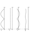
- FIG. 10 is a diagram showing an example 1 of each current and the capacitor voltage of the smoothing capacitor when the current output from the rectifying unit is smoothed by the smoothing unit and the current flowing through the inverter is kept constant;
- FIG. 10 is a diagram showing an example 2 of each current and the capacitor voltage of the smoothing capacitor when the control unit controls the operation of the inverter to reduce the current flowing through the smoothing capacitor;
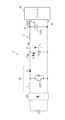
- 1 is a diagram schematically showing a configuration of a power converter according to Embodiment 1;
- FIG. FIG. 2 is a diagram schematically showing the configuration of an inverter;
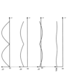
- FIG. 10 is a diagram showing an example 3 of each current and the capacitor voltage of the smoothing capacitor when the control unit controls the operation of the inverter to reduce the current flowing through the smoothing capacitor;
- FIG. 4 is a waveform diagram showing surge voltages in the case of a comparative example (without snubber capacitor) and the surge voltage in the case of Embodiment 1 (with snubber capacitor);
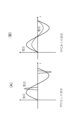
- FIG. 5 is a diagram showing a configuration example of a power conversion device according to a modification of Embodiment 1; (A) shows the waveform without PFC, and (B) shows the waveform with PFC.
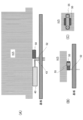
- (A) is a side view showing the arrangement of snubber capacitors in a power converter according to Embodiment 2;
- (B) is a side view showing a snubber capacitor fixing member;
- (C) is a snubber capacitor;
- 2 is a front view showing a fixing member of FIG.
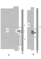
- (A) is a side view showing the arrangement of snubber capacitors in a power converter according to Embodiment 3
- (B) is a side view showing a damping member that is a fixing member for the snubber capacitors.
- FIG. 10 is a diagram showing the configuration of an air conditioner as a refrigeration cycle-applied device according to Embodiment 5;
- a power conversion device and a refrigeration cycle application device will be described below with reference to the drawings.
- the following embodiments are merely examples, and the embodiments can be combined as appropriate and each embodiment can be modified as appropriate.
- inverter control using pulsation which is a technique underlying the embodiments, will be described. to 5” will be explained.
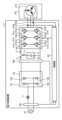
- FIG. 1 is a diagram showing a configuration example of a power converter 1a that performs inverter control using pulsation.
- the power converter 1 a is connected to a power supply (for example, commercial power supply) 10 and a compressor 201 .
- the power conversion device 1 a converts first AC power having a power supply voltage Vs supplied from the power supply 10 into second AC power having desired amplitude and phase, and supplies the second AC power to the compressor 201 .
- the power converter 1a includes a voltage/current detection unit 501, a reactor 11, a rectification unit 20 which is a rectification circuit, a voltage detection unit 502, a smoothing unit 31 including a smoothing capacitor 30, an inverter 40, and a current detection unit 313a. , 313 b and a control unit 60 .
- the power conversion device 1a is a motor drive device that drives the motor 208 .
- the voltage/current detection unit 501 detects the voltage value and current value of the first AC power of the power supply voltage Vs supplied from the power supply 10 and outputs the detected voltage value and current value to the control unit 60 .
- Reactor 11 is connected, for example, between voltage/current detector 501 and rectifier 20 .
- the rectifying section 20 has a bridge circuit composed of rectifying elements (diodes) 131 to 134, rectifies the first AC power of the power supply voltage Vs supplied from the power supply 10, and outputs it.
- the rectifier 20 performs full-wave rectification.
- Voltage detection section 502 detects the voltage value of the power rectified by rectification section 20 and outputs the detected voltage value to control section 60 .
- Smoothing section 31 is connected to the output end of rectifying section 20 via voltage detecting section 502 .
- the smoothing section 31 has a smoothing capacitor 30 as a smoothing element, and smoothes the power rectified by the rectifying section 20 .
- the smoothing capacitor 30 is, for example, an electrolytic capacitor, a film capacitor, or the like.
- the smoothing capacitor 30 has a capacity for smoothing the power rectified by the rectifying unit 20, and the voltage generated in the smoothing capacitor 30 by smoothing does not have the full-wave rectified waveform of the power supply 10, but has a DC component of the power supply.
- the waveform has a waveform in which voltage ripples corresponding to 10 frequencies are superimposed, and does not pulsate greatly.
- the frequency of this voltage ripple is a two-fold component of the frequency of the power supply voltage Vs when the power supply 10 is single-phase, and a six-fold component is the main component when the power supply 10 is three-phase. If the power input from power supply 10 and the power output from inverter 40 do not change, the amplitude of this voltage ripple is determined by the capacity of smoothing capacitor 30 . For example, it pulsates in such a range that the maximum value of the voltage ripple generated in the smoothing capacitor 30 is less than twice the minimum value.
- the inverter 40 is connected to both ends of the smoothing capacitor 30 (that is, both ends of the smoothing section 31).
- the inverter 40 has switching elements 311a to 311f and freewheeling diodes 312a to 312f.
- the inverter 40 turns on and off the switching elements 311a to 311f under the control of the control unit 60, converts the power output from the rectifying unit 20 and the smoothing capacitor 30 into second AC power having a desired amplitude and phase, and compresses it. output to the machine 201.
- Current detection units 313 a and 313 b each detect a current value of one phase out of three phase currents output from inverter 40 and output the detected current value to control unit 60 .
- Compressor 201 is a load having a motor 208 for driving the compressor.
- the motor 208 rotates according to the amplitude and phase of the second AC power supplied from the inverter 40 and performs compression operation.
- the load torque of the compressor 201 can often be regarded as a constant torque load.
- the arrangement of each configuration shown in FIG. 1 is an example, and the arrangement of each configuration is not limited to the example shown in FIG.
- the reactor 11 may be arranged after the rectifying section 20 .
- the voltage/current detector 501, the voltage detector 502, and the current detectors 313a and 313b may be collectively referred to as detectors.
- the voltage value and current value detected by the voltage/current detection unit 501, the voltage value detected by the voltage detection unit 502, and the current values detected by the current detection units 313a and 313b may be referred to as detection values. .
- the control unit 60 acquires the voltage value and the current value of the first AC power of the power supply voltage Vs from the voltage/current detection unit 501, acquires the voltage value of the power rectified by the rectification unit 20 from the voltage detection unit 502, A current value of the second AC power having a desired amplitude and phase converted by the inverter 40 is obtained from the current detection units 313a and 313b.
- the control unit 60 controls the operation of the inverter 40, specifically, ON/OFF of the switching elements 311a to 311f included in the inverter 40, using the detection values detected by the respective detection units.
- control unit 60 causes the inverter 40 to output the second AC power including pulsation corresponding to the pulsation of the power flowing into the smoothing capacitor 30 from the rectifying unit 20 to the compressor 201 as a load.
- controls the behavior of The pulsation according to the pulsation of the power flowing into the smoothing capacitor 30 is, for example, pulsation that varies depending on the frequency of the pulsation of the power flowing into the smoothing capacitor 30 .
- the control unit 60 suppresses the current flowing through the smoothing capacitor 30 .
- the control unit 60 does not have to use all the detection values acquired from each detection unit, and may perform control using some of the detection values.
- the load generated by the inverter 40 and the compressor 201 can be regarded as a constant load. are connected, the following description will be given.
- the current flowing from the rectifier 20 is current I1
- the current flowing to the inverter 40 is current I2
- the current flowing from the smoothing capacitor 30 is current I3 .
- the current I2 is the sum of the currents I1 and I3 .
- Current I 3 can be expressed as the difference between currents I 2 and I 1 , namely current I 2 -current I 1 .
- the current I3 has a positive direction in which the smoothing capacitor 30 is discharged and a negative direction in which the smoothing capacitor 30 is charged. That is, current may flow into or out of the smoothing capacitor 30 .
- FIG. 2 shows, as Example 1, the currents I 1 to I 3 and the capacitor of the smoothing capacitor 30 when the current output from the rectifier 20 is smoothed by the smoothing capacitor 30 and the current I 2 flowing through the inverter 40 is kept constant.
- FIG. 4 is a diagram showing an example of voltage Vdc; From the top, current I 1 , current I 2 , current I 3 , and capacitor voltage Vdc of smoothing capacitor 30 generated according to current I 3 are shown.
- the vertical axis of the currents I 1 , I 2 and I 3 indicates the current value [A]
- the vertical axis of the capacitor voltage Vdc indicates the voltage value [V]. All horizontal axes indicate time t.
- the currents I 2 and I 3 are actually superimposed with the carrier components of the inverter 40, they are omitted here. The same shall apply to the following.
- the control unit 60 controls the current I2 flowing through the inverter 40 so as to reduce the current I3 flowing through the smoothing capacitor 30, that is, controls the operation of the inverter 40.
- FIG. 3 shows, as example 2, currents I 1 to I 3 and smoothing capacitor 30 when the control unit 60 of the power converter 1a controls the operation of the inverter 40 to reduce the current I 3 flowing through the smoothing capacitor 30.
- FIG. 4 is a diagram showing an example of capacitor voltage Vdc; From the top, current I 1 , current I 2 , current I 3 , and capacitor voltage Vdc of smoothing capacitor 30 generated according to current I 3 are shown.
- the vertical axis of the currents I 1 , I 2 and I 3 indicates the current value [A]
- the vertical axis of the capacitor voltage Vdc indicates the voltage value [V]. All horizontal axes indicate time t.
- the control unit 60 of the power converter 1a controls the operation of the inverter 40 so that the current I2 shown in FIG. By reducing the frequency component of the current flowing into the capacitor 30, the current I3 flowing into the smoothing capacitor 30 can be reduced. Specifically, control unit 60 controls the operation of inverter 40 so that current I 2 containing a pulsating current whose main component is the frequency component of current I 1 flows through inverter 40 .
- the frequency component of current I1 is determined by the frequency of the alternating current supplied from power supply 10 and the configuration of rectifying section 20 . Therefore, the control unit 60 can make the frequency component of the pulsating current superimposed on the current I2 a component having a predetermined amplitude and phase.
- the frequency component of the pulsating current superimposed on the current I2 has a waveform similar to the frequency component of the current I1 .
- the control unit 60 reduces the current I3 flowing through the smoothing capacitor 30 and reduces the pulsating current generated in the capacitor voltage Vdc. Voltage can be reduced.
- Controlling the pulsation of the current flowing through the inverter 40 by controlling the operation of the inverter 40 by the control unit 60 is the same as controlling the pulsation of the first AC power output from the inverter 40 to the compressor 201 . is.
- Control unit 60 controls the operation of inverter 40 so that the pulsation contained in the second AC power output from inverter 40 is smaller than the pulsation of the power output from rectifying unit 20 .
- the control unit 60 controls the voltage ripple of the capacitor voltage Vdc, that is, the voltage ripple generated in the smoothing capacitor 30 so that the second AC power output from the inverter 40 includes pulsation corresponding to the pulsation of the power flowing into the smoothing capacitor 30 .
- the amplitude and phase of pulsation contained in the second AC power output from the inverter 40 are controlled so as to be smaller than the voltage ripple generated in the smoothing capacitor 30 when the power is not supplied.
- the control unit 60 controls the current ripple that flows into and out of the smoothing capacitor 30 when the second AC power output from the inverter 40 does not include pulsation corresponding to the pulsation of the power flowing into the smoothing capacitor 30 .
- the amplitude and phase of the pulsation included in the second AC power output from the inverter 40 are controlled so as to be smaller than the current ripple generated in the capacitor 30 .
- the control shown in FIG. 2 means that the second AC power output from the inverter 40 does not include pulsation corresponding to the pulsation of the power flowing into the smoothing capacitor 30 .
- the alternating current supplied from the power supply 10 is not particularly limited, and may be single-phase or three-phase.
- the control unit 60 may determine the frequency component of the pulsating current to be superimposed on the current I2 according to the first AC power supplied from the power supply 10 . Specifically, when the first AC power supplied from the power supply 10 is single-phase, the control unit 60 sets the pulsating waveform of the current I2 flowing in the inverter 40 to twice the frequency of the first AC power. Frequency components, or when the first AC power supplied from the power supply 10 is three-phase, control to a shape obtained by adding a DC component to a pulsating waveform whose main component is a frequency component six times the frequency of the first AC power. do.
- the pulsation waveform is, for example, the shape of the absolute value of a sine wave or the shape of a sine wave.
- the control section 60 may add at least one frequency component of integral multiples of the frequency of the sine wave to the pulsating waveform as a predetermined amplitude.
- the pulsating waveform may be in the shape of a rectangular wave or in the shape of a triangular wave.
- the control unit 60 may set the amplitude and phase of the pulsation waveform to predetermined values.
- the control unit 60 may use the voltage applied to the smoothing capacitor 30 or the current flowing through the smoothing capacitor 30 to calculate the amount of pulsation contained in the second AC power output from the inverter 40 .
- the amount of pulsation contained in the second AC power output from the inverter 40 may be calculated using the voltage or current of the first AC power supplied from the inverter 40 .
- the control unit 60 can be realized by, for example, a processing circuit.
- a processing circuit may be implemented by, for example, a processor and memory.
- the processor is, for example, a CPU (Central Processing Unit), a processing unit, an arithmetic unit, a microprocessor, a microcomputer, a processor, a DSP (also called a Digital Signal Processor), or a system LSI (Large Scale Integration).
- the memory is, for example, nonvolatile or volatile semiconductor memory such as RAM (Random Access Memory), ROM (Read Only Memory), and flash memory.
- the control unit 60 controls the operation of the inverter 40 based on the detection values obtained from the respective detection units, and the current I 2 , by superimposing the pulsation of the frequency component corresponding to the frequency component of the current I1 flowing from the rectifying section 20, the current I3 flowing through the smoothing capacitor 30 is reduced.
- the electric power converter 1a reduces the current I3 flowing through the smoothing capacitor 30, so that it becomes possible to use the smoothing capacitor 30 with a smaller ripple current resistance than when the control of Example 2 is not performed. .
- the power conversion device 1a can reduce the capacity of the smoothing capacitor 30 to be mounted, as compared with the case where the control of Example 2 is not performed, by reducing the pulsating voltage of the capacitor voltage Vdc.
- the power converter 1 a can reduce the number of smoothing capacitors 30 constituting the smoothing unit 31 .
- the power converter 1a controls the operation of the inverter 40 so that the pulsation contained in the second AC power is smaller than the pulsation of the power output from the rectifier 20.
- the pulsation component superimposed on the current I2 flowing through the inverter 40 can be suppressed from becoming excessive.
- the superimposition of the pulsating component increases the effective value of the current flowing through the inverter 40, the motor 208, etc. compared to the non-superimposed state. 40 current capacity, an increase in loss in the inverter 40, an increase in loss in the motor 208, etc., can be suppressed.
- the power converter 1a can suppress the vibration of the compressor 201 caused by the pulsation of the current I2 by performing the control of Example 2.
- FIG. 4 is a diagram schematically showing the configuration of power converter 1 according to Embodiment 1. As shown in FIG. In FIG. 4, the same reference numerals as those shown in FIG. 1 are attached to the same or corresponding configurations as those shown in FIG. FIG. 5 schematically shows a configuration of inverter 40. In FIG. In FIG. 5, the same reference numerals as those shown in FIG. 1 are attached to the same or corresponding configurations as those shown in FIG.
- the power conversion device 1 includes a rectifying section 20 as a rectifying circuit, a smoothing capacitor 30 , an inverter 40 , a snubber capacitor 50 and a control section 60 .
- the rectifying section 20 rectifies the first alternating current supplied from the power supply 10 and outputs the rectified current (also referred to as “first current”) I1 .
- the smoothing capacitor 30 is connected between the output terminals of the rectifying section 20 .
- the inverter 40 has input terminals 41 and 42, and converts a current (also referred to as a "second current") I2 of the current I1 input to the input terminals 41 and 42 into a second alternating current. output.
- a snubber capacitor 50 is connected between the inputs 41 and 42 at a position close to the inputs 41 and 42 .
- the proximate position is, for example, directly to the input ends 41, 42, directly to wiring connected to the input ends 41, 42, or the like.
- the control unit 60 controls the inverter 40 so that the second alternating current includes pulsations corresponding to the pulsations of the current I2 .
- C represents the electric capacity [F] of the snubber capacitor 50
- Ls represents the inductance [H] of the wiring connected to the input terminals 41 and 42
- I2 represents the current output from the inverter 40.
- V surge represents the surge voltage [V] of the current I2 output from the inverter 40
- Vcc represents the voltage [V] across the smoothing capacitor 30
- the snubber capacitor 50 preferably satisfies the following condition (1).
- the impedance of the first circuit which is a circuit from one of the input terminals of the inverter 40 (for example, the input terminal 42) to the other input terminal (for example, the input terminal 41) via the snubber capacitor 50, is the input of the inverter 40. It is desirable that the impedance is smaller than the impedance of the second circuit, which is the circuit from one of the terminals (for example, the input terminal 42) to the other of the input terminals (for example, the input terminal 41) via the smoothing capacitor 30.
- a surge voltage V surge which is an electromotive voltage due to a surge, is expressed by the following equation (3).
- Ls represents the inductance [H] of the wiring connected to the input terminals 41 and 42
- I2MAX represents the maximum input current [A] when the current I2 is assumed to be a sine wave.
- Equation (1) can be expressed as in Equation (6) below.
- Equation (6) can be expressed as Equation (7) below using Equations (3) and (5), and Equation (7) is the same as Equation (1).
- FIG. 6 is a diagram showing an example 3 of each current and the capacitor voltage Vdc of the smoothing capacitor 30 when the control unit 60 controls the operation of the inverter 40 to reduce the current I3 flowing through the smoothing capacitor 30 .
- FIG. 6 shows current I 1 , current I 2 , current I 3 , and capacitor voltage Vdc of smoothing capacitor 30 generated according to current I 3 in order from the top.
- the vertical axis of the currents I 1 , I 2 and I 3 indicates the current value [A]
- the vertical axis of the capacitor voltage Vdc indicates the voltage value [V]. All horizontal axes indicate time t.
- the control unit 60 of the power conversion device 1 controls the operation of the inverter 40 so that the current I2 shown in FIG. 20 to the smoothing capacitor 30, and the current I3 flowing to the smoothing capacitor 30 can be reduced. Specifically, control unit 60 controls the operation of inverter 40 so that current I2 containing a pulsating current whose main component is the frequency component of current I1 flows through inverter 40 .
- the frequency component of current I1 is determined by the frequency of the alternating current supplied from power supply 10 and the configuration of rectifying section 20 . Therefore, the control unit 60 can make the frequency component of the pulsating current superimposed on the current I2 a component having a predetermined amplitude and phase.
- the frequency component of the pulsating current superimposed on the current I2 has a waveform similar to the frequency component of the current I1 .
- the control unit 60 reduces the current I3 flowing through the smoothing capacitor 30, as shown in FIG. , the pulsating voltage generated in the capacitor voltage Vdc can be reduced.
- Controlling the pulsation of the current I2 flowing through the inverter 40 by controlling the operation of the inverter 40 by the control unit 60 means controlling the pulsation of the first AC power output from the inverter 40 to the compressor 201. are the same.
- Control unit 60 controls the operation of inverter 40 so that the pulsation contained in the second AC power output from inverter 40 is smaller than the pulsation of the power output from rectifying unit 20 .
- the control unit 60 controls the voltage ripple of the capacitor voltage Vdc, that is, the voltage ripple generated in the smoothing capacitor 30 so that the second AC power output from the inverter 40 includes pulsation corresponding to the pulsation of the power flowing into the smoothing capacitor 30 .
- the amplitude and phase of pulsation contained in the second AC power output from the inverter 40 are controlled so as to be smaller than the voltage ripple generated in the smoothing capacitor 30 when the power is not supplied.
- the control unit 60 controls the current ripple that flows into and out of the smoothing capacitor 30 when the second AC power output from the inverter 40 does not include pulsation corresponding to the pulsation of the power flowing into the smoothing capacitor 30 .
- the amplitude and phase of the pulsation included in the second AC power output from the inverter 40 are controlled so as to be smaller than the current ripple generated in the capacitor 30 .
- Embodiment 1 The peak value of the current I2 in FIG. 6 showing the first embodiment is .pi./2 times the value of the current I2 in FIG. 3 showing the comparative example, and the surge is also .pi./2 times.
- the surge voltage can be suppressed by including the snubber capacitor 50 .
- FIG. 7 is a waveform diagram showing the surge voltage in the case of the comparative example (without snubber capacitor) and the surge voltage in the case of Embodiment 1 (with snubber capacitor). As shown in FIG. 7, the snubber capacitor 50 reduces the peak value of the surge voltage and suppresses ringing.
- ⁇ Modification of Embodiment 1> 8 is a diagram illustrating a configuration example of a power converter according to a modification of Embodiment 1.
- FIG. 8 the same reference numerals as those shown in FIG. 4 are attached to the same or corresponding configurations as those shown in FIG.
- the power conversion device according to the modification has a booster circuit (that is, a boost chopper circuit) composed of a reactance (L), a diode (D), and a switching element (IGBT) as a power factor correction circuit (PFC) 35. is different from the example shown in FIG.
- FIG. 9(A) shows the waveform without PFC
- FIG. 9(B) shows the waveform with PFC.
- the current is not a sine wave and there is a phase delay, so the power factor is low. , with a high power factor.
- FIG. 10A is a side view showing the arrangement of snubber capacitors 50 of the power converter according to Embodiment 2.
- FIG. 10(B) is a side view showing the fixing member 55 of the snubber capacitor 50
- FIG. 10(C) is a front view showing the fixing member 55 of the snubber capacitor 50 (that is, the device of FIG. view from below).
- a power converter according to the second embodiment is the power converter 1 or 2 described in the first embodiment.
- the snubber capacitor 50 is arranged so as to be in contact with the heat sink H/S as a cooler, and the , it is fixed (for example, screwed) to the heat sink H/S with a fixing member 55 .
- the substrate is provided with the circuitry of the power converter.
- the inverter 40 is arranged in contact with or in the vicinity of the heat sink H/S.
- the inverter 40 and the circuit on the substrate are connected by lead wires 43 .
- Snubber capacitor 50 and the circuit on the substrate are connected by lead wire 52 .
- the snubber capacitor 50 is placed in the air gap between the heat sink and the substrate, and the circuit loop from the smoothing capacitor 30 to the three-phase inverter 40 is made smaller, so that the switching loop of the smoothing capacitor 30 and the inverter 40 is reduced. becomes smaller. As a result, the parasitic inductance component is reduced, so that switching noise can be reduced.
- FIG. 11(A) is a side view showing the arrangement of snubber capacitors 50 in a power converter according to Embodiment 3, and FIG. is a side view showing.
- the power converter according to the third embodiment is the power converter 1 or 2 described in the first embodiment.
- the power converter according to the third embodiment includes a heat sink H/S having a recess, and at least part of the snubber capacitor 50 is arranged in the recess and A lead 52 connects the circuit and the snubber capacitor 50 .
- a damping member for example, elastic member, resin, etc.
- the contact area between the snubber capacitor 50 and the heat sink can be increased, so heat radiation efficiency can be increased.
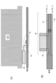
- FIG. 12A is a side view showing the arrangement of snubber capacitors in a power converter according to Embodiment 4, and FIG. 12B is a cross-sectional view showing wiring layers forming part of the snubber capacitors.
- a power converter according to the fourth embodiment is the power converter 1 or 2 described in the first embodiment.
- the snubber capacitor 50 includes a chip capacitor 56 arranged on the substrate, and first wiring 57 and first wiring 57 connected to the chip capacitor 56 and respectively arranged on both sides of the substrate. 2 wirings 58 and . Therefore, in addition to the electric capacity of the chip capacitor, the electric capacity between wirings can be obtained, and the capacity of the capacitor can be increased.
- the snubber capacitor 50 can be arranged in the space between the heat sink and the substrate, so the structure can be simplified.
- FIG. 13 is a diagram showing the configuration of an air conditioner 5 as a refrigeration cycle application device according to Embodiment 5.
- the air conditioner 5 has a power conversion device 1 and a refrigeration cycle device 200 .
- the refrigerating cycle applied equipment is, for example, an air conditioner, a refrigerator, and the like.
- the power conversion device of the air conditioner 5 the power conversion device described in any one of the first to fourth embodiments can be adopted.
- the refrigeration cycle device 200 includes a compressor 201, a four-way valve 202, an indoor heat exchanger 203, an expansion valve 204 as an expansion mechanism, an outdoor heat exchanger 205, and refrigerant pipes that sequentially connect these components. 206. Further, inside the compressor 201, a compression mechanism 207 for compressing refrigerant and a motor 208 for operating the compression mechanism 207 (for example, the motor 208 in Embodiments 1 to 4) are provided inside the compressor 201. Also, the motor 208 is driven by one of the inverters 40 of the power converter 1 .
- the air conditioner 5 according to Embodiment 5 it is possible to prevent circuit malfunction due to an unexpected open state and short-circuit path due to element failure at low cost without increasing the number of parts. Therefore, it is possible to reduce the loss of the power converter 1, contribute to energy saving, and reduce global warming.
Landscapes
- Engineering & Computer Science (AREA)
- Power Engineering (AREA)
- Microelectronics & Electronic Packaging (AREA)
- Physics & Mathematics (AREA)
- Thermal Sciences (AREA)
- Mechanical Engineering (AREA)
- General Engineering & Computer Science (AREA)
- Inverter Devices (AREA)
Priority Applications (4)
| Application Number | Priority Date | Filing Date | Title |
|---|---|---|---|
| CN202180103978.9A CN118202568A (zh) | 2021-11-12 | 2021-11-12 | 电力转换装置和制冷循环应用设备 |
| PCT/JP2021/041676 WO2023084726A1 (ja) | 2021-11-12 | 2021-11-12 | 電力変換装置及び冷凍サイクル適用機器 |
| JP2023559337A JPWO2023084726A1 (cg-RX-API-DMAC7.html) | 2021-11-12 | 2021-11-12 | |
| US18/698,896 US20250226769A1 (en) | 2021-11-12 | 2021-11-12 | Power conversion device and refrigeration cycle applied equipment |
Applications Claiming Priority (1)
| Application Number | Priority Date | Filing Date | Title |
|---|---|---|---|
| PCT/JP2021/041676 WO2023084726A1 (ja) | 2021-11-12 | 2021-11-12 | 電力変換装置及び冷凍サイクル適用機器 |
Publications (1)
| Publication Number | Publication Date |
|---|---|
| WO2023084726A1 true WO2023084726A1 (ja) | 2023-05-19 |
Family
ID=86335392
Family Applications (1)
| Application Number | Title | Priority Date | Filing Date |
|---|---|---|---|
| PCT/JP2021/041676 Ceased WO2023084726A1 (ja) | 2021-11-12 | 2021-11-12 | 電力変換装置及び冷凍サイクル適用機器 |
Country Status (4)
| Country | Link |
|---|---|
| US (1) | US20250226769A1 (cg-RX-API-DMAC7.html) |
| JP (1) | JPWO2023084726A1 (cg-RX-API-DMAC7.html) |
| CN (1) | CN118202568A (cg-RX-API-DMAC7.html) |
| WO (1) | WO2023084726A1 (cg-RX-API-DMAC7.html) |
Citations (7)
| Publication number | Priority date | Publication date | Assignee | Title |
|---|---|---|---|---|
| JPH0819267A (ja) * | 1994-06-27 | 1996-01-19 | Okuma Mach Works Ltd | インバータ制御装置 |
| JP2003219661A (ja) * | 2002-01-24 | 2003-07-31 | Toshiba Mach Co Ltd | サーボアンプ |
| JP2007295739A (ja) * | 2006-04-26 | 2007-11-08 | Sharp Corp | 直流電源装置 |
| JP2015133281A (ja) * | 2014-01-15 | 2015-07-23 | 三菱電機株式会社 | 端子台、及びこの端子台を備えた電力変換装置 |
| WO2016163201A1 (ja) * | 2015-04-07 | 2016-10-13 | 三菱電機株式会社 | 電力変換装置 |
| WO2019159317A1 (ja) * | 2018-02-16 | 2019-08-22 | 三菱電機株式会社 | 電力変換装置およびこれを用いた空気調和装置 |
| JP2019161757A (ja) * | 2018-03-08 | 2019-09-19 | ナブテスコ株式会社 | Ac−ac電力変換装置 |
Family Cites Families (9)
| Publication number | Priority date | Publication date | Assignee | Title |
|---|---|---|---|---|
| JP2954333B2 (ja) * | 1990-11-28 | 1999-09-27 | 株式会社日立製作所 | 交流電動機可変速システム |
| JP2002291260A (ja) * | 2001-03-26 | 2002-10-04 | Mitsubishi Electric Corp | モータ制御装置及びこれを用いた圧縮機 |
| JP4575704B2 (ja) * | 2003-04-22 | 2010-11-04 | パナソニック株式会社 | モータ制御装置、圧縮機、空気調和機、及び冷蔵庫 |
| JP6789654B2 (ja) * | 2016-04-04 | 2020-11-25 | 東芝キヤリア株式会社 | 電源装置 |
| JP2017212833A (ja) * | 2016-05-27 | 2017-11-30 | セイコーエプソン株式会社 | ロボット、モータードライバーおよび電子機器 |
| JP6776046B2 (ja) * | 2016-07-29 | 2020-10-28 | 株式会社マキタ | 電動作業機 |
| US9837952B1 (en) * | 2016-12-16 | 2017-12-05 | Hamilton Sundstrand Corporation | Reducing resonant effects of reactive loads in electric motor systems |
| KR102570579B1 (ko) * | 2018-07-13 | 2023-08-24 | 엘지전자 주식회사 | 냉동기 |
| EP4207573B1 (en) * | 2020-09-30 | 2026-04-29 | Daikin Industries, Ltd. | Power conversion device |
-
2021
- 2021-11-12 JP JP2023559337A patent/JPWO2023084726A1/ja active Pending
- 2021-11-12 CN CN202180103978.9A patent/CN118202568A/zh not_active Withdrawn
- 2021-11-12 US US18/698,896 patent/US20250226769A1/en active Pending
- 2021-11-12 WO PCT/JP2021/041676 patent/WO2023084726A1/ja not_active Ceased
Patent Citations (7)
| Publication number | Priority date | Publication date | Assignee | Title |
|---|---|---|---|---|
| JPH0819267A (ja) * | 1994-06-27 | 1996-01-19 | Okuma Mach Works Ltd | インバータ制御装置 |
| JP2003219661A (ja) * | 2002-01-24 | 2003-07-31 | Toshiba Mach Co Ltd | サーボアンプ |
| JP2007295739A (ja) * | 2006-04-26 | 2007-11-08 | Sharp Corp | 直流電源装置 |
| JP2015133281A (ja) * | 2014-01-15 | 2015-07-23 | 三菱電機株式会社 | 端子台、及びこの端子台を備えた電力変換装置 |
| WO2016163201A1 (ja) * | 2015-04-07 | 2016-10-13 | 三菱電機株式会社 | 電力変換装置 |
| WO2019159317A1 (ja) * | 2018-02-16 | 2019-08-22 | 三菱電機株式会社 | 電力変換装置およびこれを用いた空気調和装置 |
| JP2019161757A (ja) * | 2018-03-08 | 2019-09-19 | ナブテスコ株式会社 | Ac−ac電力変換装置 |
Also Published As
| Publication number | Publication date |
|---|---|
| CN118202568A (zh) | 2024-06-14 |
| JPWO2023084726A1 (cg-RX-API-DMAC7.html) | 2023-05-19 |
| US20250226769A1 (en) | 2025-07-10 |
Similar Documents
| Publication | Publication Date | Title |
|---|---|---|
| CN104702107B (zh) | 转换器电路、电动机驱动控制装置、空气调节器、冰箱 | |
| JP6072924B2 (ja) | 直流電源装置、およびそれを備えた冷凍サイクル適用機器 | |
| US9225258B2 (en) | Backflow preventing means, power converting device, and refrigerating and air-conditioning apparatus | |
| JP7345674B2 (ja) | 電力変換装置、モータ駆動装置および冷凍サイクル適用機器 | |
| US9742336B2 (en) | Air conditioner with variable power converter | |
| JP7345673B2 (ja) | 電力変換装置、モータ駆動装置および冷凍サイクル適用機器 | |
| JP7471442B2 (ja) | 電力変換装置、モータ駆動装置および冷凍サイクル適用機器 | |
| JPWO2005006531A1 (ja) | 三相電力変換装置および電力変換装置 | |
| JP4657301B2 (ja) | 電動機駆動装置及び圧縮機駆動装置 | |
| CN106533208A (zh) | 直流电源装置和空调机 | |
| KR20140112297A (ko) | 전력변환장치, 및 이를 구비하는 공기조화기 | |
| JP7325673B2 (ja) | 電力変換装置及び空調機 | |
| US20200358365A1 (en) | Power converter and air-conditioning apparatus using the same | |
| JP7179222B2 (ja) | 電力変換装置、冷凍サイクル装置及び空気調和機 | |
| CN116783811A (zh) | 电力转换装置、马达驱动装置以及制冷循环应用设备 | |
| WO2022172418A1 (ja) | 電力変換装置、モータ駆動装置および冷凍サイクル適用機器 | |
| US20250226769A1 (en) | Power conversion device and refrigeration cycle applied equipment | |
| WO2023105792A1 (ja) | 電力変換装置、モータ駆動装置および冷凍サイクル適用機器 | |
| JP2000324843A (ja) | 電源装置とその電源装置を備えた空気調和機 | |
| WO2023095265A1 (ja) | 電力変換装置、モータ駆動装置および冷凍サイクル適用機器 | |
| WO2025120780A1 (ja) | 電力変換装置、モータ駆動装置および冷凍サイクル適用機器 | |
| WO2016125255A1 (ja) | 電力変換装置及び空気調和装置 | |
| JP2023009146A (ja) | 直流電源装置および空気調和機 | |
| WO2023238229A1 (ja) | 電力変換装置、モータ駆動装置及び冷凍サイクル適用機器 | |
| JP2021072667A (ja) | 直流電源装置および冷凍サイクル適用機器 |
Legal Events
| Date | Code | Title | Description |
|---|---|---|---|
| 121 | Ep: the epo has been informed by wipo that ep was designated in this application |
Ref document number: 21964081 Country of ref document: EP Kind code of ref document: A1 |
|
| WWE | Wipo information: entry into national phase |
Ref document number: 2023559337 Country of ref document: JP |
|
| WWE | Wipo information: entry into national phase |
Ref document number: 18698896 Country of ref document: US |
|
| WWE | Wipo information: entry into national phase |
Ref document number: 202180103978.9 Country of ref document: CN |
|
| NENP | Non-entry into the national phase |
Ref country code: DE |
|
| 122 | Ep: pct application non-entry in european phase |
Ref document number: 21964081 Country of ref document: EP Kind code of ref document: A1 |
|
| WWP | Wipo information: published in national office |
Ref document number: 18698896 Country of ref document: US |