WO2023238229A1 - 電力変換装置、モータ駆動装置及び冷凍サイクル適用機器 - Google Patents
電力変換装置、モータ駆動装置及び冷凍サイクル適用機器 Download PDFInfo
- Publication number
- WO2023238229A1 WO2023238229A1 PCT/JP2022/022941 JP2022022941W WO2023238229A1 WO 2023238229 A1 WO2023238229 A1 WO 2023238229A1 JP 2022022941 W JP2022022941 W JP 2022022941W WO 2023238229 A1 WO2023238229 A1 WO 2023238229A1
- Authority
- WO
- WIPO (PCT)
- Prior art keywords
- power
- capacitor
- conversion device
- inverter
- current
- Prior art date
Links
- 238000006243 chemical reaction Methods 0.000 title claims abstract description 96
- 238000005057 refrigeration Methods 0.000 title claims description 13
- 239000003990 capacitor Substances 0.000 claims abstract description 123
- 238000001514 detection method Methods 0.000 claims abstract description 56
- 230000010349 pulsation Effects 0.000 claims abstract description 49
- 230000002265 prevention Effects 0.000 claims abstract description 19
- 230000006872 improvement Effects 0.000 claims description 4
- 238000009499 grossing Methods 0.000 description 69
- 238000010586 diagram Methods 0.000 description 18
- 230000006835 compression Effects 0.000 description 8
- 238000007906 compression Methods 0.000 description 8
- 230000007423 decrease Effects 0.000 description 7
- 230000006866 deterioration Effects 0.000 description 7
- 230000007246 mechanism Effects 0.000 description 7
- 239000003507 refrigerant Substances 0.000 description 6
- 230000032683 aging Effects 0.000 description 4
- 230000004048 modification Effects 0.000 description 4
- 238000012986 modification Methods 0.000 description 4
- 238000001816 cooling Methods 0.000 description 3
- 230000005611 electricity Effects 0.000 description 3
- 238000010438 heat treatment Methods 0.000 description 3
- 238000012545 processing Methods 0.000 description 3
- 230000000694 effects Effects 0.000 description 2
- 238000000034 method Methods 0.000 description 2
- 238000012544 monitoring process Methods 0.000 description 2
- 230000008569 process Effects 0.000 description 2
- 239000004065 semiconductor Substances 0.000 description 2
- 238000013459 approach Methods 0.000 description 1
- 230000006399 behavior Effects 0.000 description 1
- 239000004568 cement Substances 0.000 description 1
- 230000008859 change Effects 0.000 description 1
- 238000007599 discharging Methods 0.000 description 1
- 238000005516 engineering process Methods 0.000 description 1
- 230000010354 integration Effects 0.000 description 1
- 230000003287 optical effect Effects 0.000 description 1
- 239000007787 solid Substances 0.000 description 1
- XLYOFNOQVPJJNP-UHFFFAOYSA-N water Substances O XLYOFNOQVPJJNP-UHFFFAOYSA-N 0.000 description 1
Images


Classifications
-
- H—ELECTRICITY
- H02—GENERATION; CONVERSION OR DISTRIBUTION OF ELECTRIC POWER
- H02M—APPARATUS FOR CONVERSION BETWEEN AC AND AC, BETWEEN AC AND DC, OR BETWEEN DC AND DC, AND FOR USE WITH MAINS OR SIMILAR POWER SUPPLY SYSTEMS; CONVERSION OF DC OR AC INPUT POWER INTO SURGE OUTPUT POWER; CONTROL OR REGULATION THEREOF
- H02M7/00—Conversion of ac power input into dc power output; Conversion of dc power input into ac power output
- H02M7/42—Conversion of dc power input into ac power output without possibility of reversal
- H02M7/44—Conversion of dc power input into ac power output without possibility of reversal by static converters
- H02M7/48—Conversion of dc power input into ac power output without possibility of reversal by static converters using discharge tubes with control electrode or semiconductor devices with control electrode
Definitions
- the present disclosure relates to a power conversion device that converts AC power supplied from an AC power source into AC power with a voltage different from the AC power and supplies it to a load, and a motor drive device and refrigeration cycle application equipment equipped with the same.
- a power conversion device that converts AC power supplied from an AC power source into AC power with a different voltage from this AC power, and supplies it to a load such as an air conditioner.
- a power converter rectifies AC power supplied from an AC power source using a diode bridge circuit, smoothes it using a smoothing capacitor, converts the smoothed power into desired AC power using an inverter made up of multiple switching elements, and converts it into a load. Output to compressor motor.
- an inrush current flows to rapidly charge the smoothing capacitor when the power is turned on. If an inrush current flows through a semiconductor component such as a diode bridge, it may exceed the withstand capacity of the component and cause it to be destroyed, so it is necessary to suppress the inrush current by using an inrush current prevention circuit.
- Patent Document 1 discloses that the device has a means for detecting the voltage of an AC power source, and when the amount of electricity determined from the voltage detected by the voltage detection means becomes equal to or less than a first set value, a torque is generated according to the reduced amount of electricity.
- a power converter that reduces the command value of the current component at a preset rate, and reduces the command value of the torque current component to zero when the amount of electricity becomes equal to or less than a second set value that is smaller than the first set value. is disclosed.
- the power conversion device disclosed in Patent Document 1 can quickly return to a normal state after power is restored from an instantaneous power outage.
- Patent Document 1 since the power conversion device disclosed in Patent Document 1 reduces the torque current only when an instantaneous power outage is detected, a large current flows through the smoothing capacitor during normal operation, which accelerates aging deterioration of the smoothing capacitor. There was a problem. In addition, it is possible to suppress ripple changes in the capacitor voltage by increasing the capacitance of the smoothing capacitor, or to use a smoothing capacitor that has a high resistance to deterioration due to ripples, but this poses the problem of increasing the size of the device.
- the present disclosure has been made in view of the above, and aims to provide a power conversion device that suppresses aging deterioration of a smoothing capacitor without increasing the size of the device.
- a power conversion device includes an inrush current prevention section that prevents inrush current, an instantaneous power outage detection section that detects an instantaneous power outage of the commercial power supply, and a power conversion device that prevents an inrush current.
- a rectifier that rectifies the first AC power supplied from the rectifier; a capacitor connected to the output end of the rectifier; and an inverter that converts it into a load and outputs it to the load.
- the power converter controls the operation of the inverter so that the inverter outputs second AC power including pulsations corresponding to the pulsations of power flowing into the capacitor from the rectifier to the load, and controls the current flowing to the capacitor. It is equipped with a section and a section.
- the power conversion device has the effect of suppressing aging deterioration of the smoothing capacitor without increasing the size of the device.
- a diagram showing the configuration of a power conversion device according to Embodiment 1 A diagram showing the current flowing from the rectifying section, the current flowing to the inverter, the current flowing from the smoothing section, and the capacitor voltage of the power conversion device according to Embodiment 1.
- Flowchart showing the operation of the control unit included in the power conversion device according to Embodiment 1 A diagram illustrating an example of a hardware configuration that implements a control unit included in the power conversion device according to Embodiment 1.
- a diagram showing the configuration of a power conversion device according to Embodiment 2 Flowchart showing the operation of the control unit included in the power conversion device according to Embodiment 2
- a diagram showing the configuration of a power conversion device according to a modification of Embodiment 2 A diagram showing the configuration of a refrigeration cycle application device according to Embodiment 3
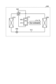
- FIG. 1 is a diagram showing the configuration of a power conversion device according to Embodiment 1.
- Power conversion device 1a is connected to commercial power source 110 and compressor 315.
- the power conversion device 1a converts the first AC power of the power supply voltage Vs supplied from the commercial power supply 110 into second AC power having an amplitude and phase different from the first AC power, and supplies the second AC power to the compressor 315. .
- the power conversion device 1a includes an inrush current prevention section 120, an instantaneous power failure detection section 502, a voltage/current detection section 501, a reactor 130, a rectification section 140, a voltage detection section 503, a smoothing section 200, an inverter 310, , current detection sections 313a and 313b, and a control section 400.
- the power conversion device 1a and the motor 314 included in the compressor 315 constitute a motor drive device 2a.
- the inrush current prevention unit 120 includes an inrush current prevention element 121 connected in series to the commercial power supply 110 and a switching element 122 connected in parallel to the inrush current prevention element 121.
- the inrush current prevention element 121 suppresses inrush current that occurs when the commercial power source 110 is turned on to the power conversion device 1a.
- Examples of the inrush current prevention element 121 include, but are not limited to, a PTC (Positive Temperature Coefficient) thermistor, a cement resistor, and a thermal fuse resistor.
- the switching element 122 short-circuits the inrush current prevention element 121 by turning on the switching element 122 during normal operation, thereby suppressing the loss that regularly occurs in the inrush current prevention element 121.
- the switching element 122 examples include, but are not limited to, a relay, a thyristor, and a triac.
- the inrush current prevention element 121 may be connected to the path from the commercial power source 110 to the smoothing section 200.
- the inrush current prevention element 121 may be connected closer to the commercial power supply 110 than the rectifier 140, or may be connected closer to the motor 314 than the rectifier 140.
- the rush current prevention element 121 may be connected to the positive electrode side or may be connected to the negative electrode side.
- the instantaneous power failure detection unit 502 detects the voltage of the commercial power supply 110 and outputs the detected value to the control unit 400.
- the voltage and current detection unit 501 detects the voltage and current values of the first AC power of the power supply voltage Vs supplied from the commercial power supply 110 and outputs the detected voltage and current values to the control unit 400.
- the reactor 130 is connected between the rush current prevention section 120 and the rectification section 140.
- the rectifier 140 includes a rectifier circuit 500 and rectifies the first AC power of the power supply voltage Vs supplied from the commercial power supply 110 and outputs the rectifier.
- the rectifier circuit 500 is a bridge circuit configured by rectifying elements 141, 142, 143, and 144.
- the rectifier 140 performs full-wave rectification.
- Voltage detection section 503 detects the voltage value of the power rectified by rectification section 140 and outputs the detected voltage value to control section 400.
- Smoothing section 200 is connected to the output end of rectifying section 140 via voltage detecting section 503 .
- the smoothing section 200 has a capacitor 210 as a smoothing element, and smoothes the power rectified by the rectifying section 140. Examples of the capacitor 210 include an electrolytic capacitor and a film capacitor, but are not limited thereto. Capacitor 210 has a capacity to smooth the power rectified by rectifier 140.
- the voltage generated in the capacitor 210 due to smoothing does not have a full-wave rectified waveform of the commercial power supply 110, but has a waveform in which a voltage ripple corresponding to the frequency of the commercial power supply 110 is superimposed on a DC component, and does not pulsate significantly.
- the main component of the frequency of this voltage ripple is a component twice the frequency of the power supply voltage Vs when the commercial power supply 110 is single-phase, and a component six times the frequency of the power supply voltage Vs when the commercial power supply 110 is three-phase.
- the amplitude of this voltage ripple is determined by the capacitance of capacitor 210. For example, the voltage ripple generated in capacitor 210 pulsates within a range where the maximum value is less than twice the minimum value.
- the inverter 310 is connected to the smoothing section 200. That is, inverter 310 is connected to both ends of capacitor 210.
- the inverter 310 has switching elements 311a, 311b, 311c, 311d, 311e, 311f and free wheel diodes 312a, 312b, 312c, 312d, 312e, 312f.
- the inverter 310 turns on and off the switching elements 311a, 311b, 311c, 311d, 311e, and 311f under the control of the control unit 400, and converts the power output from the rectifying unit 140 and the smoothing unit 200 to an amplitude different from the first AC power. It is converted into second AC power having a phase and output to the compressor 315.
- the control unit 400 acquires the voltage value and current value of the first AC power of the power supply voltage Vs from the voltage/current detection unit 501. Further, the control unit 400 acquires the voltage value of the power rectified by the rectification unit 140 from the voltage detection unit 503. Further, the control unit 400 acquires the current value of the second AC power having a different amplitude and phase from the first AC power converted by the inverter 310 from the current detection units 313a and 313b. The control unit 400 uses the detection values detected by each detection unit to control the operation of the inverter 310, specifically, the on/off of switching elements 311a, 311b, 311c, 311d, 311e, and 311f included in the inverter 310. .
- Current I3 can be expressed as the difference between current I2 and current I1, ie, current I2-I1.
- the current I3 has a positive direction in the discharging direction of the smoothing section 200 and a negative direction in the charging direction of the smoothing section 200. That is, a current may flow into the smoothing portion 200, and a current may flow out of the smoothing portion 200.
- the control section 400 controls the current I2 flowing through the inverter 310 so as to reduce the current I3 flowing through the smoothing section 200. That is, the control section 400 controls the operation of the inverter 310 so as to reduce the current I3 flowing through the smoothing section 200.
- the control unit 400 of the power conversion device 1a controls the operation of the inverter 310 so that the current I2 as shown in FIG.
- the frequency component of the current flowing into the smoothing section 200 can be reduced, and the current I3 flowing into the smoothing section 200 can be reduced.
- the control unit 400 controls the operation of the inverter 310 so that a current I2 including a pulsating current whose main component is the frequency component of the current I1 flows through the inverter 310.
- the frequency component of the current I1 is determined by the frequency of the alternating current supplied from the commercial power supply 110 and the configuration of the rectifier 140. Therefore, the control unit 400 can set the frequency component of the pulsating current superimposed on the current I2 to a component having a predetermined amplitude and phase.
- the frequency component of the pulsating current superimposed on the current I2 has a similar waveform to the frequency component of the current I1.
- the control unit 400 reduces the current I3 flowing through the smoothing unit 200 as the frequency component of the pulsating current superimposed on the current I2 approaches the frequency component of the current I1, thereby reducing the pulsating voltage generated in the capacitor voltage Vdc. I can do it.
- Controlling the pulsation of the current flowing through the inverter 310 by the control unit 400 controlling the operation of the inverter 310 is the same as controlling the pulsation of the first AC power output from the inverter 310 to the compressor 315. be.
- Control unit 400 controls the operation of inverter 310 so that the pulsations included in the second AC power output from inverter 310 are smaller than the pulsations in the power output from rectifier 140.
- the control unit 400 controls the voltage ripple of the capacitor voltage Vdc, that is, the voltage ripple generated in the capacitor 210, so that the second AC power output from the inverter 310 does not include pulsations corresponding to the pulsations of the power flowing into the capacitor 210.
- the amplitude and phase of the pulsation contained in the second AC power output from the inverter 310 is controlled so that the voltage ripple that occurs in the capacitor 210 is smaller than the voltage ripple that occurs in the capacitor 210 at that time.
- the control unit 400 controls the current ripple flowing in and out of the capacitor 210 when the second AC power output from the inverter 310 does not include pulsations corresponding to the pulsations of the power flowing into the capacitor 210.
- the amplitude and phase of pulsation contained in the second AC power output from inverter 310 is controlled so that it is smaller than the generated current ripple.
- control unit 400 may set the pulsating waveform of the current I2 to a rectangular wave shape or a triangular wave shape. In this case, the control unit 400 may set the amplitude and phase of the pulsating waveform to predefined values.
- FIG. 4 is a diagram showing the current flowing from the rectifying section, the current flowing to the inverter, the current flowing from the smoothing section, and the capacitor voltage of the power conversion device according to the first embodiment.
- each current is shown when the control unit 400 does not limit the current I2 flowing through the inverter 310 when a momentary power failure occurs, but makes the current I2 before the momentary power failure equal to the current I2 during the momentary power failure period.
- An example of I1, I2, I3 and the capacitor voltage Vdc of the smoothing section 200 is shown.
- current I1, current I2, current I3, and capacitor voltage Vdc are shown in order from the top. Note that the capacitor voltage Vdc is generated according to the current I3.
- the control unit 400 controls the operation of the inverter 310 to reduce the absolute value of the current I2 flowing through the inverter 310.
- the frequency component of the pulsating current superimposed on the current I2 is the same as the frequency component of the current I1 before the instantaneous power failure
- the current I3 flowing through the smoothing section 200 can be reduced, and the absolute value of the current I2 can be reduced.
- the amount of decrease in the current I3 during the period when a momentary power failure occurs is limited. Therefore, the decrease in the capacitor voltage Vdc of the smoothing section 200 can be slowed down.
- FIG. 6 is a flowchart showing the operation of the control unit included in the power conversion device according to the first embodiment.
- the control unit 400 acquires detection values from each detection unit of the power conversion device 1a.
- the control unit 400 controls the operation of the inverter 310 based on the acquired detection value so that the current I3 flowing through the smoothing unit 200 is reduced.
- the control unit 400 determines whether an instantaneous power outage of the power supply voltage has been detected.
- the power conversion device 1a can reduce the capacitance of the mounted capacitor 210 compared to the case where the control of the first embodiment is not performed by reducing the pulsating voltage of the capacitor voltage Vdc.
- the power conversion device 1a can reduce the number of capacitors 210 that constitute the smoothing section 200. Therefore, the power conversion device 1a according to the first embodiment can suppress aging deterioration of the smoothing capacitor without increasing the size of the device. Further, since a low capacitance capacitor 210 can be used in the smoothing section 200 or the number of capacitors 210 can be reduced, the cost of parts of the power converter 1a can be reduced.
- the booster 600 is controlled by the controller 400 using full PAM (Pulse Amplitude Modulation) in which the switching element 611 continuously performs a switching operation.
- the power converter 1b performs power factor improvement control of the commercial power supply 110 using the booster 600, and makes the capacitor voltage Vdc of the capacitor 210 of the smoother 200 higher than the power supply voltage Vs.
- the rectifier 140 uses the rectifier circuit 500 and the booster 600 to rectify the first AC power supplied from the commercial power source 110 and boosts the voltage of the first AC power supplied from the commercial power source 110 .
- the rectifier circuit 500 and the booster 600 in the rectifier 140 are connected in series.
- the power conversion device 1b may detect an instantaneous power failure in the power supply voltage by using the boost ratio of the booster 600.
- the control unit 400 performs average voltage control of the smoothing unit 200, it is necessary to increase the voltage output to the inverter 310 by an amount corresponding to the voltage drop.
- the control section 400 is operated so that the on period of the switching element 611 included in the boosting section 600 becomes longer. That is, the control unit 400 is operated so that the energy accumulated in the reactor 130 when the switching element 611 is turned on becomes larger.
- Control unit 400 may calculate the amount of pulsation included in the second AC power output from inverter 310 using the voltage applied to capacitor 210 or the current flowing to capacitor 210. Further, the control unit 400 may calculate the amount of pulsation included in the second AC power output from the inverter 310 using the voltage or current of the first AC power supplied from the commercial power supply 110. .
- FIG. 9 is a flowchart showing the operation of the control unit included in the power conversion device according to the second embodiment.
- the control unit 400 acquires detection values from each detection unit of the power conversion device 1b.
- the control unit 400 controls the operation of the inverter 310 based on the acquired detection value so that the current I3 flowing through the smoothing unit 200 is reduced.
- the control unit 400 controls the booster unit 600 to perform power factor improvement control of the commercial power supply 110 and average voltage control of the capacitor voltage Vdc of the capacitor 210 of the smoothing unit 200 based on the acquired detection value.
- Refrigeration cycle application equipment 900 includes a compressor 315 with a built-in motor 314, a four-way valve 902, an indoor heat exchanger 906, an expansion valve 908, and an outdoor heat exchanger 910 in the first and second embodiments. is attached through refrigerant piping 912.
- the indoor heat exchanger 906 acts as a condenser and releases heat, and the outdoor heat exchanger 910 acts as an evaporator and absorbs heat.
- the outdoor heat exchanger 910 acts as a condenser and releases heat, and the indoor heat exchanger 906 acts as an evaporator and absorbs heat.
- the expansion valve 908 reduces the pressure of the refrigerant and expands it.
Landscapes
- Engineering & Computer Science (AREA)
- Power Engineering (AREA)
- Inverter Devices (AREA)
Abstract
電力変換装置(1a)は、突入電流を防止する突入電流防止部(120)と、商用電源(110)の瞬停を検出する瞬停検出部(502)と、商用電源(110)から供給される第1の交流電力を整流する整流部(140)と、整流部(140)の出力端に接続されるコンデンサ(210)と、コンデンサ(210)の両端に接続され、整流部(140)及びコンデンサ(210)から出力される電力を第2の交流電力に変換し、モータ(314)を有する圧縮機(315)に出力するインバータ(310)と、整流部(140)からコンデンサ(210)に流入する電力の脈動に応じた脈動を含む第2の交流電力をインバータ(310)から圧縮機(315)に出力するようにインバータ(310)の動作を制御し、コンデンサ(210)に流れる電流を抑制する制御部(400)と、を備える。
Description
本開示は、交流電源から供給される交流電力をこの交流電力とは電圧が異なる交流電力に変換して負荷に供給する電力変換装置並びにこれを備えるモータ駆動装置及び冷凍サイクル適用機器に関する。
従来、交流電源から供給される交流電力をこの交流電力とは電圧が異なる交流電力に変換し、空気調和機などの負荷に供給する電力変換装置がある。電力変換装置は交流電源から供給される交流電力をダイオードブリッジ回路で整流し、さらに平滑コンデンサで平滑し、平滑した電力を複数のスイッチング素子からなるインバータで所望の交流電力に変換し、負荷である圧縮機モータに出力する。
このような電力変換装置は、比較的大容量な平滑コンデンサを備えるため、電源投入時には平滑コンデンサを急激に充電するために突入電流が流れる。ダイオードブリッジなどの半導体部品に突入電流が流れると、部品の耐量を超えることで破壊される恐れがあるため、突入電流防止回路を使用することによって突入電流を抑制する必要がある。
一方、「瞬停」と称される瞬時停電が発生した場合、電力変換装置が運転を継続し電力を負荷である圧縮機モータに供給し続けると、急激に平滑コンデンサの電荷が減少することで直流母線電圧が低下する。この状態で復電し正常状態に復帰すると、平滑コンデンサを再充電することにより再突入電流が流れるため、この再突入電流によっても部品が破壊される恐れがある。このため、運転中に瞬停が発生した場合は一旦運転を停止させ、復電後に再運転させることで運転を継続させることが多い。しかしながら、一度運転を停止させた場合、負荷である圧縮機モータに印加する電圧及び周波数をゼロから再上昇させる必要があるため、瞬停発生前の状態に復帰させるまでに時間がかかるといった問題があった。
このような背景から、瞬停を検出する手段をもち、瞬停発生時に負荷に供給する電力を制限することで直流母線電圧の減少を抑制する構成が知られている。例えば、特許文献1には、交流電源の電圧を検出する手段をもち、電圧検出手段で検出した電圧から求めた電気量が第1の設定値以下となったとき低下した電気量に応じてトルク電流成分の指令値を予め設定された割合で低減し、電気量が第1の設定値よりも小さい第2の設定値以下となったときトルク電流成分の指令値をゼロに低減する電力変換装置が開示されている。特許文献1に開示される電力変換装置は、瞬停から復電後、速やかに通常状態に復帰することができる。
しかしながら、特許文献1に開示される電力変換装置は、瞬停を検出した場合に限りトルク電流を低減するため、通常動作時に平滑コンデンサに大きな電流が流れることで平滑コンデンサの経年劣化が加速する、という問題があった。また、平滑コンデンサの容量を大きくすることでコンデンサ電圧のリプル変化を抑制したり、リプルによる劣化耐量の大きい平滑コンデンサを使用したりする方法も考えられるが、装置が大型化する問題があった。
本開示は、上記に鑑みてなされたものであって、装置を大型化することなく平滑コンデンサの経年劣化を抑制した電力変換装置を得ることを目的とする。
上述した課題を解決し、目的を達成するために、本開示に係る電力変換装置は、突入電流を防止する突入電流防止部と、商用電源の瞬停を検出する瞬停検出部と、商用電源から供給される第1の交流電力を整流する整流部と、整流部の出力端に接続されるコンデンサと、コンデンサの両端に接続され、整流部及びコンデンサから出力される電力を第2の交流電力に変換して負荷に出力するインバータとを有する。電力変換装置は、整流部からコンデンサに流入する電力の脈動に応じた脈動を含む第2の交流電力をインバータから負荷に出力するようにインバータの動作を制御し、コンデンサに流れる電流を抑制する制御部と、を備える。
本開示に係る電力変換装置は、装置を大型化することなく平滑コンデンサの経年劣化を抑制できるという効果を奏する。
以下に、実施の形態に係る電力変換装置、モータ駆動装置及び冷凍サイクル適用機器を図面に基づいて詳細に説明する。
実施の形態1.
図1は、実施の形態1に係る電力変換装置の構成を示す図である。電力変換装置1aは商用電源110及び圧縮機315に接続される。電力変換装置1aは商用電源110から供給される電源電圧Vsの第1の交流電力を第1の交流電力とは異なる振幅及び位相を有する第2の交流電力に変換し、圧縮機315に供給する。電力変換装置1aは、突入電流防止部120と、瞬停検出部502と、電圧電流検出部501と、リアクトル130と、整流部140と、電圧検出部503と、平滑部200と、インバータ310と、電流検出部313a,313bと、制御部400と、を備える。なお電力変換装置1aと圧縮機315が備えるモータ314とは、モータ駆動装置2aを構成している。
図1は、実施の形態1に係る電力変換装置の構成を示す図である。電力変換装置1aは商用電源110及び圧縮機315に接続される。電力変換装置1aは商用電源110から供給される電源電圧Vsの第1の交流電力を第1の交流電力とは異なる振幅及び位相を有する第2の交流電力に変換し、圧縮機315に供給する。電力変換装置1aは、突入電流防止部120と、瞬停検出部502と、電圧電流検出部501と、リアクトル130と、整流部140と、電圧検出部503と、平滑部200と、インバータ310と、電流検出部313a,313bと、制御部400と、を備える。なお電力変換装置1aと圧縮機315が備えるモータ314とは、モータ駆動装置2aを構成している。
突入電流防止部120は、商用電源110に対して直列に接続される突入電流防止素子121と、突入電流防止素子121に並列に接続されるスイッチング素子122とによって構成される。突入電流防止素子121は、商用電源110を電力変換装置1aに対して投入する際に発生する突入電流を抑制する。突入電流防止素子121には、PTC(Positive Temperature Coefficient)サーミスタ、セメント抵抗及び温度ヒューズ抵抗を例示できるが、これらに限定はされない。スイッチング素子122は、通常動作時にスイッチング素子122をオンすることで突入電流防止素子121を短絡し、突入電流防止素子121に定常的に生じる損失を抑制する。スイッチング素子122は、リレー、サイリスタ及びトライアックを例示できるが、これらに限定はされない。突入電流防止素子121は、商用電源110から平滑部200までの経路に接続されればよい。例えば、突入電流防止素子121は、整流部140よりも商用電源110側に接続されてもよいし、整流部140よりもモータ314側に接続されてもよい。また、突入電流防止素子121は、正極側に接続されてもよいし、負極側に接続されてもよい。
瞬停検出部502は、商用電源110の電圧を検出し、検出した値を制御部400に出力する。電圧電流検出部501は、商用電源110から供給される電源電圧Vsの第1の交流電力の電圧値及び電流値を検出し、検出した電圧値及び電流値を制御部400に出力する。リアクトル130は、突入電流防止部120と整流部140との間に接続される。整流部140は、整流回路500を有し、商用電源110から供給される電源電圧Vsの第1の交流電力を整流して出力する。実施の形態1に係る電力変換装置1aにおいて、整流回路500は、整流素子141,142,143,144によって構成されるブリッジ回路である。整流部140は全波整流を行う。電圧検出部503は、整流部140によって整流された電力の電圧値を検出し、検出した電圧値を制御部400に出力する。平滑部200は、電圧検出部503を介して整流部140の出力端に接続される。平滑部200は、平滑素子としてコンデンサ210を有し、整流部140によって整流された電力を平滑化する。コンデンサ210は、電解コンデンサ及びフィルムコンデンサを例示できるが、これらに限定はされない。コンデンサ210は、整流部140によって整流された電力を平滑化する容量を有する。平滑化によりコンデンサ210に発生する電圧は、商用電源110の全波整流波形形状ではなく、直流成分に商用電源110の周波数に応じた電圧リプルが重畳した波形形状となり、大きく脈動しない。この電圧リプルの周波数は、商用電源110が単相の場合は電源電圧Vsの周波数の2倍成分となり、商用電源110が三相の場合は6倍成分が主成分となる。商用電源110から入力される電力とインバータ310から出力される電力が変化しない場合、この電圧リプルの振幅は、コンデンサ210の容量によって決まる。例えば、コンデンサ210に発生する電圧リプルは、最大値が最小値の2倍未満となるような範囲で脈動している。
インバータ310は、平滑部200に接続される。すなわち、インバータ310は、コンデンサ210の両端に接続される。インバータ310はスイッチング素子311a,311b,311c,311d,311e,311f及び還流ダイオード312a,312b,312c,312d,312e,312fを有する。インバータ310は、制御部400の制御によってスイッチング素子311a,311b,311c,311d,311e,311fをオンオフし、整流部140及び平滑部200から出力される電力を第1の交流電力とは異なる振幅及び位相を有する第2の交流電力に変換して圧縮機315に出力する。電流検出部313a,313bは、インバータ310から出力される3相の電流のうち1相の電流値を検出し、検出した電流値を制御部400に出力する。なお、制御部400は、インバータ310から出力される3相の電流値のうち2相の電流値を取得することで、インバータ310から出力される残り1相の電流値を算出することができる。圧縮機315は、圧縮機駆動用のモータ314を有する負荷である。モータ314は、インバータ310から供給される第2の交流電力の振幅及び位相に応じて回転し、圧縮動作を行う。圧縮機315が空気調和機で使用される密閉型圧縮機の場合、圧縮機315の負荷トルクは定トルク負荷とみなせる場合が多い。
なお、電力変換装置1aにおいて図1に示す各構成要素の配置は一例であり、各構成要素の配置は図1で示される例に限定されない。例えば、リアクトル130は、整流部140の後段に配置されてもよい。以降の説明において電圧電流検出部501、電圧検出部503及び電流検出部313a,313bをまとめて「検出部」と称することがある。また、電圧電流検出部501で検出された電圧値及び電流値と、電圧検出部503で検出された電圧値と、電流検出部313a,313bで検出された電流値とを、「検出値」と称することがある。
制御部400は、電源電圧Vsの第1の交流電力の電圧値及び電流値を電圧電流検出部501から取得する。また、制御部400は、整流部140によって整流された電力の電圧値を電圧検出部503から取得する。また、制御部400は、インバータ310によって変換された第1の交流電力とは異なる振幅及び位相を有する第2の交流電力の電流値を電流検出部313a,313bから取得する。制御部400は、各検出部によって検出された検出値を用いて、インバータ310の動作、具体的には、インバータ310が有するスイッチング素子311a,311b,311c,311d,311e,311fのオンオフを制御する。実施の形態1において、制御部400は、整流部140から平滑部200のコンデンサ210に流入する電力の脈動に応じた脈動を含む第2の交流電力を、インバータ310から負荷である圧縮機315に出力するようにインバータ310の動作を制御する。平滑部200のコンデンサ210に流入する電力の脈動に応じた脈動とは、例えば、平滑部200のコンデンサ210に流入する電力の脈動の周波数などによって変動する脈動である。これにより、制御部400は、平滑部200のコンデンサ210に流れる電流を抑制する。なお、制御部400は各検出部から取得した全ての検出値を用いなくてもよく、一部の検出値を用いて制御を行ってもよい。以降において、制御部400の動作を、通常動作時と瞬停検出時とに分けて説明する。
まず、通常動作時の制御部400の動作について説明する。実施の形態1に係る電力変換装置1aにおいて、インバータ310及び圧縮機315によって発生する負荷が一定の負荷とみなすことができ、平滑部200から出力される電流で見た場合、平滑部200に定電流負荷が接続されているものとして、以降の説明を行う。ここで、図1に示すように、整流部140から流れる電流を電流I1とし、インバータ310に流れる電流を電流I2とし、平滑部200から流れる電流をI3とする。電流I2は、電流I1とI3とを併せた電流となる。電流I3は、電流I2と電流I1との差分、すなわち電流I2-I1として表すことができる。電流I3は、平滑部200の放電方向を正方向とし、平滑部200の充電方向を負方向とする。すなわち、平滑部200には電流が流入することもあり、電流が流出することもある。
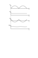
図2は、実施の形態1に係る電力変換装置の整流部から流れる電流、インバータに流れる電流、平滑部から流れる電流及びコンデンサ電圧を示す図である。図2は、平滑部200で整流部140から出力される電流を平滑化し、インバータ310に流れる電流I2を一定にした場合の各電流I1,I2,I3及び平滑部200のコンデンサ電圧Vdcの例を示している。図2では、上から順に、電流I1、電流I2、電流I3及びコンデンサ電圧Vdcを示している。なお、コンデンサ電圧Vdcは、電流I3に応じて発生する。電流I1,I2,I3の縦軸は電流値を示し、コンデンサ電圧Vdcの縦軸は電圧値を示している。横軸は、すべて時間tを示している。なお、電流I2,I3には、実際にはインバータ310のキャリア成分が重畳されるがここでは省略する。以降についても同様とする。図2に示すように、電力変換装置1aにおいて、仮に、整流部140から流れる電流I1が平滑部200によって平滑された場合、インバータ310に流れる電流I2は一定の電流値となる。しかしながら、平滑部200のコンデンサ210には大きな電流I3が流れ、劣化の要因となる。このため、実施の形態1に係る電力変換装置1aにおいて、制御部400は、平滑部200に流れる電流I3を低減するようにインバータ310に流れる電流I2を制御する。すなわち制御部400は、平滑部200に流れる電流I3を低減するようにインバータ310の動作を制御する。
図3は、実施の形態1に係る電力変換装置の整流部から流れる電流、インバータに流れる電流、平滑部から流れる電流及びコンデンサ電圧を示す図である。図3は、制御部400がインバータ310の動作を制御して平滑部200に流れる電流I3を低減したときの各電流I1,I2,I3及び平滑部200のコンデンサ電圧Vdcの例を示している。図3では、上から順に、電流I1、電流I2、電流I3及びコンデンサ電圧Vdcを示している。なお、コンデンサ電圧Vdcは、電流I3に応じて発生する。電流I1,I2,I3の縦軸は電流値を示し、コンデンサ電圧Vdcの縦軸は電圧値を示している。横軸はすべて時間tを示している。電力変換装置1aの制御部400は、図3に示すような電流I2がインバータ310に流れるようにインバータ310の動作を制御することによって、図2に示した例と比較して、整流部140から平滑部200に流れこむ電流の周波数成分を低減し、平滑部200に流れる電流I3を低減することができる。具体的には、制御部400は、電流I1の周波数成分を主成分とした脈動電流を含む電流I2がインバータ310に流れるようにインバータ310の動作を制御する。
電流I1の周波数成分は、商用電源110から供給される交流電流の周波数及び整流部140の構成によって決定される。そのため、制御部400は、電流I2に重畳する脈動電流の周波数成分を、予め定めた振幅及び位相を有する成分とすることができる。電流I2に重畳される脈動電流の周波数成分は、電流I1の周波数成分の相似波形となる。制御部400は、電流I2に重畳する脈動電流の周波数成分を電流I1の周波数成分に近づけていくにつれて、平滑部200に流れる電流I3を低減し、コンデンサ電圧Vdcに発生する脈動電圧を低減することができる。
制御部400がインバータ310の動作を制御することによってインバータ310に流れる電流の脈動を制御することは、インバータ310から圧縮機315に出力される第1の交流電力の脈動を制御することと同じである。制御部400は、インバータ310から出力される第2の交流電力に含まれる脈動が、整流部140から出力される電力の脈動よりも小さくなるようにインバータ310の動作を制御する。制御部400は、コンデンサ電圧Vdcの電圧リプル、すなわちコンデンサ210に発生する電圧リプルが、インバータ310から出力される第2の交流電力にコンデンサ210に流入する電力の脈動に応じた脈動が含まれないときのコンデンサ210に発生する電圧リプルよりも小さくなるように、インバータ310から出力される第2の交流電力に含まれる脈動の振幅及び位相を制御する。または、制御部400は、コンデンサ210に流出入する電流リプルが、インバータ310から出力される第2の交流電力にコンデンサ210に流入する電力の脈動に応じた脈動が含まれないときのコンデンサ210に発生する電流リプルよりも小さくなるように、インバータ310から出力される第2の交流電力に含まれる脈動の振幅及び位相を制御する。なお、「インバータ310から出力される第2の交流電力にコンデンサ210に流入する電力の脈動に応じた脈動が含まれないとき」とは、図2に示すように、平滑部200で整流部140から出力される電流を平滑化し、インバータ310に流れる電流I2を一定にした場合のことである。
なお、商用電源110から供給される交流電流については特に限定されず、単相であってもよいし、3相であってもよい。制御部400は、電流I2に重畳する脈動電流の周波数成分について、商用電源110から供給される第1の交流電力に応じて決定すればよい。具体的には、商用電源110から供給される第1の交流電力が単相の場合、制御部400は、インバータ310に流れる電流I2の脈動波形を、第1の交流電力の周波数の2倍の周波数成分を主成分とする脈動波形に直流成分を加算した形状に制御する。また、商用電源110から供給される第1の交流電力が3相の場合、制御部400は、インバータ310に流れる電流I2の脈動波形を、第1の交流電力の周波数の6倍の周波数成分を主成分とする脈動波形に直流成分を加算した形状に制御する。制御部400は、電流I2の脈動波形は、例えば、正弦波の絶対値の形状、又は正弦波の形状とする。この場合、制御部400は、正弦波の周波数の整数倍の成分のうち少なくとも一つの周波数成分を、予め規定された振幅として脈動波形に加算してもよい。また、制御部400は、電流I2の脈動波形を、矩形波の形状、又は三角波の形状としてもよい。この場合、制御部400は、脈動波形の振幅及び位相を予め規定された値としてよい。
制御部400は、コンデンサ210にかかる電圧又はコンデンサ210に流れる電流を用いて、インバータ310から出力される第2の交流電力に含まれる脈動の脈動量を演算してもよいし、商用電源110から供給される第1の交流電力の電圧又は電流を用いて、インバータ310から出力される第2の交流電力に含まれる脈動の脈動量を演算してもよい。
つづいて、瞬停検出時の制御部400の動作について説明する。瞬停発生時には、商用電源110から供給される電圧よりも平滑部200におけるコンデンサ電圧の方が大きくなるため、コンデンサ210に電荷が充電されない。この状態でインバータ310から負荷に電力を供給し続けるとコンデンサ210は放電し、電流I3が正方向に流れ平滑部200から電流が流出することによって、コンデンサ電圧は低下する。このときインバータ310から負荷に通常動作時と同じ量の第2の交流電力を供給し続けた場合、コンデンサ210に残された電荷のみによって電力を賄うため、コンデンサ電圧が急激に低下する。この状態で復電した場合、コンデンサ210の再充電量が多いために再突入電流が発生する。したがって、瞬停発生時には、インバータ310に流れる電流I2を制限するように制御部400を動作させ、第2の交流電力を減少させれば、コンデンサ電圧の低下を緩やかにし、復電時の再突入電流を抑制できる。
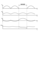
図4は、実施の形態1に係る電力変換装置の整流部から流れる電流、インバータに流れる電流、平滑部から流れる電流及びコンデンサ電圧を示す図である。図4では、瞬停発生時に制御部400がインバータ310に流れる電流I2を制限せずに、瞬停が発生する前の電流I2と瞬停発生期間中の電流I2とを等しくした場合の各電流I1,I2,I3及び平滑部200のコンデンサ電圧Vdcの例を示している。図4では、上から順に、電流I1、電流I2、電流I3及びコンデンサ電圧Vdcを示している。なお、コンデンサ電圧Vdcは、電流I3に応じて発生する。電流I1,I2,I3の縦軸は電流値を示し、コンデンサ電圧Vdcの縦軸は電圧値を示している。横軸はすべて時間tを示している。図4に示すように、瞬停発生時に電源電圧Vsが遮断されると、整流部140から流れる電流I1は、ゼロとなる。このとき、電流I2は制限されないため、負荷に出力する電力が低減されずにコンデンサ210に残された電荷のみによって、負荷に出力する電力が賄われ、コンデンサ電圧の低下量が大きくなる。この状態で復電すると、再突入電流が大きくなる。
図5は、実施の形態1に係る電力変換装置の整流部から流れる電流、インバータに流れる電流、平滑部から流れる電流及びコンデンサ電圧を示す図である。図5は、制御部400が、瞬停発生時にインバータ310の動作を制御してインバータ310に流れる電流I2を低減した場合の各電流I1,I2,I3及び平滑部200のコンデンサ電圧Vdcの例を示している。図5に示すように、瞬停発生時に電源電圧Vsが遮断されると、整流部140から流れる電流I1はゼロとなる。瞬停検出部502により瞬停を検出すると、制御部400は、インバータ310に流れる電流I2の絶対値を減少させるようにインバータ310の動作を制御する。このとき、電流I2に重畳する脈動電流の周波数成分は瞬停発生前の電流I1の周波数成分と同じであるため、平滑部200に流れる電流I3は低減が可能であり、かつ、電流I2の絶対値を減少させるため、瞬停発生期間中の電流I3の減少量を制限する。したがって、平滑部200のコンデンサ電圧Vdcの減少を緩やかにすることができる。
瞬停検出部502は、入力電圧を常時監視し、入力電圧の状態を制御部400に出力することによって制御動作を実現する。瞬停検出部502は、入力電源電圧のゼロクロスを検出してもよいし、入力電源電圧の値を直接監視してもよい。電源電圧のゼロクロスを検出する場合、交流電圧が一定の周期でゼロ点を横切ることを利用する。電源電圧のゼロクロス点の有無を検出し、ゼロクロス点が予め設定された検出時間の間検出されないときに、制御部400は電源電圧の瞬停が生じたと判断することができる。一方、入力電源電圧の値を直接監視する場合、入力電源電圧値が予め設定された値を下回った場合に、制御部400は瞬停が生じたと判断する。このとき入力電圧の低下によって瞬停状態を検出するため、瞬停のみならず瞬時電圧低下も検出することができる。以下、瞬時電圧低下を「瞬低」という。
制御部400の動作を、フローチャートを用いて説明する。図6は、実施の形態1に係る電力変換装置が備える制御部の動作を示すフローチャートである。ステップS1において、制御部400は、電力変換装置1aの各検出部から検出値を取得する。ステップS2において、制御部400は、取得した検出値に基づいて、平滑部200に流れる電流I3が低減されるようにインバータ310の動作を制御する。ステップS3において、制御部400は、電源電圧の瞬停を検出したか否かを判断する。電源電圧の瞬停を検出した場合、ステップS3でYesとなり、制御部400は、ステップS4において、インバータ310に流れる電流I2を制限し、コンデンサ電圧Vdcの低下が緩和されるようにインバータ310の動作を制御する。電源電圧の瞬停を検出しない場合、ステップS3でNoとなり、制御部400は、処理を終了する。
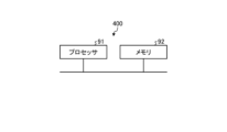
つづいて、電力変換装置1aが備える制御部400のハードウェア構成について説明する。図7は、実施の形態1に係る電力変換装置が備える制御部を実現するハードウェア構成の一例を示す図である。制御部400は、プロセッサ91及びメモリ92により実現される。
プロセッサ91は、CPU(Central Processing Unit)、中央処理装置、処理装置、演算装置、マイクロプロセッサ、マイクロコンピュータ、プロセッサ、DSP(Digital Signal Processor)、又はシステムLSI(Large Scale Integration)である。メモリ92は、RAM(Random Access Memory)、ROM(Read Only Memory)、フラッシュメモリー、EPPROM(Erasable Programmable Read Only Memory)、EEPROM(登録商標)(Electrically Erasable Programmable Read Only Memory)といった不揮発性又は揮発性の半導体メモリを例示できる。また、メモリ92は、これらに限定されず、磁気ディスク、光ディスク、コンパクトディスク、ミニディスク又はDVD(Digital Versatile Disc)でもよい。
以上説明したように、実施の形態1に係る電力変換装置1aにおいて、制御部400は、各検出部から取得した検出値に基づいてインバータ310の動作を制御し、インバータ310に流れる電流I2に、整流部140から流れる電流I1の周波数成分に応じた周波数成分の脈動を重畳することで平滑部200に流れる電流I3を低減する。これにより、電力変換装置1aは、平滑部200に流れる電流I3が低減することによって、実施の形態1の制御を行わない場合と比較して、リプル電流耐量の小さなコンデンサ210の使用が可能となる。または、電力変換装置1aは、コンデンサ電圧Vdcの脈動電圧が低下することによって、実施の形態1の制御を行わない場合と比較して、搭載するコンデンサ210の容量を小さくすることができる。電力変換装置1aは、例えば、複数のコンデンサ210で平滑部200を構成していた場合、平滑部200を構成するコンデンサ210の本数を低減することができる。したがって、実施の形態1に係る電力変換装置1aは、装置を大型化することなく、平滑コンデンサの経年劣化を抑制することができる。また、平滑部200に低容量のコンデンサ210を用いたり、コンデンサ210の本数を減らしたりできるため、電力変換装置1aの部品コストを低減できる。
また、実施の形態1に係る電力変換装置1aは、第2の交流電力に含まれる脈動が、整流部140から出力される電力の脈動よりも小さくなるようにインバータ310の動作を制御することによって、インバータ310に流れる電流I2に重畳する脈動成分が過大になるのを抑制できる。脈動成分の重畳は、インバータ310、モータ314などを通流する電流実効値を非重畳状態と比較して増加させることとなるが、重畳する脈動成分が過大になるのを抑制することによってインバータ310の電流容量、インバータ310の損失増加、モータ314の損失増加などを抑制したシステムを提供することが可能となる。
また、実施の形態1に係る電力変換装置1aは、電流I2の脈動に起因して発生する圧縮機315の振動を抑制することができる。
実施の形態2.
図8は、実施の形態2に係る電力変換装置の構成を示す図である。電力変換装置1bは、商用電源110及び圧縮機315に接続される。電力変換装置1bは商用電源110から供給される電源電圧Vsの第1の交流電力を第1の交流電力とは異なる振幅及び位相を有する第2の交流電力に変換し、圧縮機315に供給する。電力変換装置1bは、突入電流防止部120と、瞬停検出部502と、電圧電流検出部501と、整流部140と、リアクトル130と、昇圧部600と、電圧検出部503と、平滑部200と、インバータ310と、電流検出部313a,313bと、制御部400と、を備える。なお、電力変換装置1bでは、整流回路500、リアクトル130及び昇圧部600によって整流部140を構成している。また電力変換装置1bと、圧縮機315が備えるモータ314とは、モータ駆動装置2bを構成している。
図8は、実施の形態2に係る電力変換装置の構成を示す図である。電力変換装置1bは、商用電源110及び圧縮機315に接続される。電力変換装置1bは商用電源110から供給される電源電圧Vsの第1の交流電力を第1の交流電力とは異なる振幅及び位相を有する第2の交流電力に変換し、圧縮機315に供給する。電力変換装置1bは、突入電流防止部120と、瞬停検出部502と、電圧電流検出部501と、整流部140と、リアクトル130と、昇圧部600と、電圧検出部503と、平滑部200と、インバータ310と、電流検出部313a,313bと、制御部400と、を備える。なお、電力変換装置1bでは、整流回路500、リアクトル130及び昇圧部600によって整流部140を構成している。また電力変換装置1bと、圧縮機315が備えるモータ314とは、モータ駆動装置2bを構成している。
電力変換装置1bにおいて、リアクトル130は、整流回路500と昇圧部600との間に接続される。昇圧部600はスイッチング素子611及び整流素子621を有する。昇圧部600は、制御部400の制御によってスイッチング素子611をオンオフし、整流回路500から出力された電力を昇圧し、昇圧した電力を平滑部200に出力する。なお、ここでは昇圧部600がスイッチング素子611を一つ備える構成を例に挙げたが、スイッチング素子611を複数備えた構成としてもよい。昇圧部600がスイッチング素子611を複数備える場合には、複数のスイッチング素子611の各々に対して、複数の整流素子で構成されたブリッジ回路が並列に接続される。
本実施の形態において、昇圧部600は、制御部400によってスイッチング素子611が連続的にスイッチング動作を行うフルPAM(Pulse Amplitude Modulation)で制御される。電力変換装置1bは、昇圧部600によって商用電源110の力率改善制御を行い、平滑部200のコンデンサ210のコンデンサ電圧Vdcを電源電圧Vsよりも高い電圧にする。整流部140は、整流回路500及び昇圧部600によって、商用電源110から供給される第1の交流電力を整流するとともに、商用電源110から供給される第1の交流電力の電圧を昇圧する。実施の形態2に係る電力変換装置1bでは、整流部140において整流回路500と昇圧部600とは、直列に接続されている。
制御部400は、電圧電流検出部501から電源電圧Vsの第1の交流電力の電圧値及び電流値を取得し、電圧検出部503から整流部140によって昇圧された電力の電圧値を取得し、電流検出部313a,313bからインバータ310によって変換された第1の交流電力とは異なる振幅及び位相を有する第2の交流電力の電流値を取得する。制御部400は、各検出部によって検出された検出値を用いて、整流部140の昇圧部600の動作、具体的には昇圧部600が有するスイッチング素子611のオンオフを制御する。また、制御部400は、各検出部によって検出された検出値を用いて、インバータ310の動作、具体的には、インバータ310が有するスイッチング素子311a,311b,311c,311d,311e,311fのオンオフを制御する。実施の形態2に係る電力変換装置1bにおいて制御部400は、整流部140の動作を制御する。制御部400は、整流部140の動作を制御し、商用電源110から供給される第1の交流電力の力率改善制御と、平滑部200のコンデンサ210の平均電圧制御とを行う。このように、電力変換装置1bは、昇圧部600が昇圧動作を行うことによって、コンデンサ210のコンデンサ電圧Vdcを上昇させ、インバータ310の出力可能電圧範囲を拡大することができる。
電力変換装置1bは、昇圧部600の昇圧比率を利用することで電源電圧の瞬停を検出してもよい。電源電圧に瞬停又は瞬低が発生した場合、第1の交流電力の電圧が低下する。制御部400は、平滑部200の平均電圧制御を行うため、電圧が低下した分だけインバータ310に出力する電圧をより大きく昇圧する必要がある。具体的には、昇圧部600が有するスイッチング素子611のオン期間が長くなるように制御部400を動作させる。すなわち、スイッチング素子611のオン時にリアクトル130に蓄積されるエネルギーがより大きくなるように制御部400を動作させる。制御部400は、目標のコンデンサ電圧と電圧検出部503で検出した実際のコンデンサ電圧とを比較することで昇圧比率を決定し、平均電圧制御を行う。したがって、昇圧比率が予め設定した値を上回った場合に、電源電圧の瞬停又は瞬低と判断するように制御部400を動作させれば、実施の形態1に係る電力変換装置1aで示した制御動作によって復電時の突入電流を防止できる。このようにすることで、入力電源電圧のゼロクロス、あるいは、入力電源電圧の値を検出することなく、電源電圧の瞬停又は瞬低を検出することができる。
なお、商用電源110から供給される交流電流については特に限定されず、単相であってもよいし、3相であってもよい。制御部400は、コンデンサ210にかかる電圧又はコンデンサ210に流れる電流を用いてインバータ310から出力される第2の交流電力に含まれる脈動の脈動量を演算してもよい。また、制御部400は、商用電源110から供給される第1の交流電力の電圧又は電流を用いてインバータ310から出力される第2の交流電力に含まれる脈動の脈動量を演算してもよい。
また、制御部400は、商用電源110から供給される第1の交流電力の周波数成分とは異なる周波数成分を含む第2の交流電力をインバータ310から圧縮機315に出力させるようにインバータ310を制御する場合には、インバータ310から圧縮機315に出力される第2の交流電力に含まれる周波数成分を、昇圧部600のスイッチング素子611をオンオフするための駆動信号に重畳させてもよい。すなわち、制御部400は、インバータ310から圧縮機315に出力する第2の交流電力の電力脈動のうち、商用電源110から供給される第1の交流電力が単相の場合は、第1の交流電力の周波数の2倍の周波数成分以外の変動周波数成分を含む電力が整流部140から出力されるように、整流部140の動作、具体的には、昇圧部600のスイッチング素子611の動作を制御する。また、制御部400は、インバータ310から圧縮機315に出力する第2の交流電力の電力脈動のうち、商用電源110から供給される第1の交流電力が3相の場合は、第1の交流電力の周波数の6倍の周波数成分以外の変動周波数成分を含む電力が整流部140から出力されるように、整流部140の動作、具体的には、昇圧部600のスイッチング素子611の動作を制御する。制御部400は、変動周波数成分を、商用電源110に対する指令値を用いて制御してもよい。また、制御部400は、変動周波数成分を、商用電源110から供給される第1の交流電力の周波数の40次までの整数倍以外の成分とするように制御してもよい。また、制御部400は、変動周波数成分を、予め設定された規格値以下になるように制御してもよい。
制御部400の動作を、フローチャートを用いて説明する。図9は、実施の形態2に係る電力変換装置が備える制御部の動作を示すフローチャートである。ステップS11において、制御部400は、電力変換装置1bの各検出部から検出値を取得する。ステップS12において、制御部400は、取得した検出値に基づいて、平滑部200に流れる電流I3が低減されるようにインバータ310の動作を制御する。ステップS13において、制御部400は、取得した検出値に基づいて、商用電源110の力率改善制御と、平滑部200のコンデンサ210のコンデンサ電圧Vdcの平均電圧制御とを行うように、昇圧部600の動作を制御する。ステップS14において、制御部400は、瞬停を検出したか否かを判断する。電源電圧の瞬停を検出した場合、ステップS14でYesとなり、ステップS15において、制御部400は、インバータ310に流れる電流I2を制限し、コンデンサ電圧Vdcの低下が緩和されるようにインバータ310の動作を制御する。電源電圧の瞬停を検出しない場合、ステップS14でNoとなり、制御部400は、処理を終了する。
電力変換装置1bにおけるその他の動作は、実施の形態1の電力変換装置1aの動作と同様である。この場合においても、電力変換装置1bは、実施の形態1の電力変換装置1aと同様の効果を得ることができる。
実施の形態2に係る電力変換装置1bは、昇圧部600によって平滑部200のコンデンサ210のコンデンサ電圧Vdcを電源電圧Vsよりも高い電圧にするため、実施の形態1に係る電力変換装置1aと比較すると、力率を改善しエネルギー効率を高めることができる。
なお、ここでは、整流部140において整流回路500と昇圧部600とが直列に接続された電力変換装置1bについて説明したが、整流部140において、整流回路500と昇圧部600とは、並列に接続されてもよい。図10は、実施の形態2の変形例に係る電力変換装置の構成を示す図である。実施の形態2の変形例に係る電力変換装置1cにおいて、昇圧部600は、スイッチング素子611と整流素子621,622,623,624とを有する。昇圧部600は、整流回路500と昇圧部600とが並列となるようにリアクトル130に接続される。整流回路500と昇圧部600とを並列に接続した実施の形態2の変形例に係る電力変換装置1cにおいても、実施の形態2に係る電力変換装置1bと同様に、力率を改善しエネルギー効率を高めることができる。
実施の形態3.
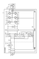
図11は、実施の形態3に係る冷凍サイクル適用機器の構成を示す図である。実施の形態3に係る冷凍サイクル適用機器900は、実施の形態1で説明した電力変換装置1a又は実施の形態2で説明した電力変換装置1bを備える。実施の形態3に係る冷凍サイクル適用機器900は、空気調和機、冷蔵庫、冷凍庫、ヒートポンプ給湯器といった冷凍サイクルを備える製品に適用することが可能である。
図11は、実施の形態3に係る冷凍サイクル適用機器の構成を示す図である。実施の形態3に係る冷凍サイクル適用機器900は、実施の形態1で説明した電力変換装置1a又は実施の形態2で説明した電力変換装置1bを備える。実施の形態3に係る冷凍サイクル適用機器900は、空気調和機、冷蔵庫、冷凍庫、ヒートポンプ給湯器といった冷凍サイクルを備える製品に適用することが可能である。
冷凍サイクル適用機器900は、実施の形態1及び実施の形態2におけるモータ314を内蔵した圧縮機315と、四方弁902と、室内熱交換器906と、膨張弁908と、室外熱交換器910とが冷媒配管912を通して取り付けられている。
圧縮機315の内部には、冷媒を圧縮する圧縮機構904と、圧縮機構904を動作させるモータ314とが設けられている。
冷凍サイクル適用機器900は、四方弁902の切替動作により暖房運転又は冷房運転をすることができる。圧縮機構904は、可変速制御されるモータ314によって駆動される。
暖房運転時には、実線矢印で示すように、冷媒が圧縮機315で加圧されて送り出され、四方弁902、室内熱交換器906、膨張弁908、室外熱交換器910及び四方弁902を通って圧縮機構904に戻る。
冷房運転時には、破線矢印で示すように、冷媒が圧縮機構904で加圧されて送り出され、四方弁902、室外熱交換器910、膨張弁908、室内熱交換器906及び四方弁902を通って圧縮機構904に戻る。
暖房運転時には、室内熱交換器906が凝縮器として作用して熱放出を行い、室外熱交換器910が蒸発器として作用して熱吸収を行う。冷房運転時には、室外熱交換器910が凝縮器として作用して熱放出を行い、室内熱交換器906が蒸発器として作用し、熱吸収を行う。膨張弁908は冷媒を減圧して膨張させる。
実施の形態3に係る冷凍サイクル適用機器900は、平滑コンデンサの経年劣化が抑制された実施の形態1に係る電力変換装置1a又は実施の形態2に係る電力変換装置1bを備えるため、長寿命化を実現できる。
以上の実施の形態に示した構成は、内容の一例を示すものであり、別の公知の技術と組み合わせることも可能であるし、要旨を逸脱しない範囲で、構成の一部を省略、変更することも可能である。
1a,1b,1c 電力変換装置、2a,2b モータ駆動装置、91 プロセッサ、92 メモリ、110 商用電源、120 突入電流防止部、121 突入電流防止素子、122,311a,311b,311c,311d,311e,311f,611 スイッチング素子、130 リアクトル、140 整流部、141,142,143,144,621,622,623,624 整流素子、200 平滑部、210 コンデンサ、310 インバータ、312a,312b,312c,312d,312e,312f 還流ダイオード、313a,313b 電流検出部、314 モータ、315 圧縮機、400 制御部、500 整流回路、501 電圧電流検出部、502 瞬停検出部、503 電圧検出部、600 昇圧部、900 冷凍サイクル適用機器、902 四方弁、904 圧縮機構、906 室内熱交換器、908 膨張弁、910 室外熱交換器、912 冷媒配管。
Claims (28)
- 突入電流を防止する突入電流防止部と、
商用電源の瞬停を検出する瞬停検出部と、
商用電源から供給される第1の交流電力を整流する整流部と、
前記整流部の出力端に接続されるコンデンサと、
前記コンデンサの両端に接続され、前記整流部及び前記コンデンサから出力される電力を第2の交流電力に変換して負荷に出力するインバータと、
前記整流部から前記コンデンサに流入する電力の脈動に応じた脈動を含む前記第2の交流電力を前記インバータから前記負荷に出力するように前記インバータの動作を制御し、前記コンデンサに流れる電流を抑制する制御部と、を備える電力変換装置。 - 前記整流部は、複数の整流素子によって構成される整流回路を備える請求項1に記載の電力変換装置。
- 前記制御部は、
前記第1の交流電力が単相の場合には、前記インバータに流れる電流の脈動波形を、前記第1の交流電力の周波数の2倍の周波数成分を主成分とする前記脈動波形に直流成分を加算した形状に制御し、
前記第1の交流電力が3相の場合には、前記脈動波形を、前記第1の交流電力の周波数の6倍の周波数成分を主成分とする前記脈動波形に直流成分を加算した形状に制御する、請求項1又は2に記載の電力変換装置。 - 前記制御部は、前記脈動波形を、正弦波の絶対値の形状又は正弦波の形状とする、請求項3に記載の電力変換装置。
- 前記整流部は、前記正弦波の周波数の整数倍の成分のうち少なくとも一つの周波数成分を規定された振幅として前記脈動波形に加算する、請求項4に記載の電力変換装置。
- 前記制御部は、前記脈動波形を、矩形波の形状又は三角波の形状とする、請求項3に記載の電力変換装置。
- 前記整流部は、前記脈動波形の振幅及び位相を規定された値とする、請求項6に記載の電力変換装置。
- 前記制御部は、前記瞬停検出部が電源電圧の瞬時停電又は瞬時電圧低下を検出した場合に、前記インバータに流れる電流を制限し、前記コンデンサの電圧低下を緩和するように記インバータの動作を制御する、請求項1から7のいずれか1項に記載の電力変換装置。
- 前記整流部は、複数の整流素子によって構成される整流回路と、前記制御部によってオンオフが制御されるスイッチング素子を有し、前記整流回路と前記コンデンサとの間に接続されて、前記整流回路によって整流された後の前記第1の交流電力の電圧を昇圧する昇圧部とを備える請求項1に記載の電力変換装置。
- 前記整流部と前記昇圧部とが直列又は並列に接続される、請求項9に記載の電力変換装置。
- 前記昇圧部は、前記スイッチング素子を複数備え、
複数の前記整流素子の各々は、複数の前記スイッチング素子の各々に並列に接続される、請求項9又は10に記載の電力変換装置。 - 前記制御部は、前記整流部の動作を制御し、前記商用電源から供給される第1の交流電力の力率改善制御及び前記コンデンサの平均電圧制御を行う、請求項9から11のいずれか1項に記載の電力変換装置。
- 前記制御部は、前記昇圧部の昇圧比により、電源電圧の瞬時停電又は瞬時電圧低下を検出した場合に、前記インバータに流れる電流を制限し、前記コンデンサの電圧低下を緩和するように前記インバータの動作を制御する、請求項9から12のいずれか1項に記載の電力変換装置。
- 前記制御部は、
前記第1の交流電力が単相の場合は、前記インバータから出力される前記第2の交流電力に含まれる脈動のうち、前記第1の交流電力の周波数の2倍の周波数成分以外の変動周波数成分を含む電力が前記整流部から出力されように、前記整流部の動作を制御し、
前記第1の交流電力が3相の場合は、前記インバータから出力される前記第2の交流電力に含まれる脈動のうち、前記第1の交流電力の周波数の6倍の周波数成分以外の変動周波数成分を含む電力が前記整流部から出力されるように、前記整流部の動作を制御する、請求項9から13のいずれか1項に記載の電力変換装置。 - 前記制御部は、前記変動周波数成分を、前記商用電源に対する指令値を用いて制御する、請求項14に記載の電力変換装置。
- 前記制御部は、前記変動周波数成分を、前記第1の交流電力の周波数の40次までの整数倍以外の成分とするように制御する、請求項14に記載の電力変換装置。
- 前記制御部は、前記変動周波数成分を、予め設定された規定値以下になるように制御する、請求項14に記載の電力変換装置。
- 前記制御部は、前記インバータから出力される前記第2の交流電力に含まれる脈動が、前記整流部から出力される電力の脈動よりも小さくなるように前記インバータの動作を制御する、請求項1から17のいずれか1項に記載の電力変換装置。
- 前記整流部は、全波整流を行い、
前記コンデンサに発生する電圧は、前記商用電源の全波整流波形形状とは異なる波形形状の電圧である、請求項1から18のいずれか1項に記載の電力変換装置。 - 前記制御部は、前記コンデンサに発生する電圧リプルが、前記インバータから出力される前記第2の交流電力に前記コンデンサに流入する電力の脈動に応じた脈動が含まれないときの前記コンデンサに発生する電圧リプルよりも小さくなるように、前記インバータから出力される第2の交流電力に含まれる脈動の振幅及び位相を制御する、請求項1から19のいずれか1項に記載の電力変換装置。
- 前記制御部は、前記コンデンサに流出入する電流リプルが、前記インバータから出力される前記第2の交流電力に前記コンデンサに流入する電力の脈動に応じた脈動が含まれないときの前記コンデンサに発生する電流リプルよりも小さくなるように、前記インバータから出力される前記第2の交流電力に含まれる脈動の振幅及び位相を制御する、請求項1から20のいずれか1項に記載の電力変換装置。
- 前記制御部は、前記コンデンサにかかる電圧又は前記コンデンサに流れる電流を用いて、前記インバータから出力される前記第2の交流電力に含まれる脈動の脈動量を演算する、請求項1から21のいずれか1項に記載の電力変換装置。
- 前記制御部は、前記第1の交流電力の電圧又は電流を用いて、前記インバータから出力される前記第2の交流電力に含まれる脈動の脈動量を演算する、請求項1から22のいずれか1項に記載の電力変換装置。
- 前記コンデンサは、電解コンデンサ又はフィルムコンデンサである、請求項1から23のいずれか1項に記載の電力変換装置。
- 前記コンデンサに発生する電圧リプルの最大値は最小値の2倍未満である、請求項1から24のいずれか1項に記載の電力変換装置。
- 前記瞬停検出部は、前記商用電源の瞬時停電又は瞬時電圧低下を検出し、入力電圧の状態を前記制御部に出力する、請求項1から25のいずれか1項に記載の電力変換装置。
- 請求項1から26のいずれか1項に記載の電力変換装置を備えるモータ駆動装置。
- 請求項1から26のいずれか1項に記載の電力変換装置を備える冷凍サイクル適用機器。
Priority Applications (1)
| Application Number | Priority Date | Filing Date | Title |
|---|---|---|---|
| PCT/JP2022/022941 WO2023238229A1 (ja) | 2022-06-07 | 2022-06-07 | 電力変換装置、モータ駆動装置及び冷凍サイクル適用機器 |
Applications Claiming Priority (1)
| Application Number | Priority Date | Filing Date | Title |
|---|---|---|---|
| PCT/JP2022/022941 WO2023238229A1 (ja) | 2022-06-07 | 2022-06-07 | 電力変換装置、モータ駆動装置及び冷凍サイクル適用機器 |
Publications (1)
| Publication Number | Publication Date |
|---|---|
| WO2023238229A1 true WO2023238229A1 (ja) | 2023-12-14 |
Family
ID=89118041
Family Applications (1)
| Application Number | Title | Priority Date | Filing Date |
|---|---|---|---|
| PCT/JP2022/022941 WO2023238229A1 (ja) | 2022-06-07 | 2022-06-07 | 電力変換装置、モータ駆動装置及び冷凍サイクル適用機器 |
Country Status (1)
| Country | Link |
|---|---|
| WO (1) | WO2023238229A1 (ja) |
Citations (5)
| Publication number | Priority date | Publication date | Assignee | Title |
|---|---|---|---|---|
| JPH05308781A (ja) * | 1992-04-28 | 1993-11-19 | Toyo Electric Mfg Co Ltd | インバータ制御装置 |
| JP2012175882A (ja) * | 2011-02-24 | 2012-09-10 | Mitsubishi Electric Corp | 電源装置及び空気調和装置 |
| JP2019161757A (ja) * | 2018-03-08 | 2019-09-19 | ナブテスコ株式会社 | Ac−ac電力変換装置 |
| WO2022091185A1 (ja) * | 2020-10-26 | 2022-05-05 | 三菱電機株式会社 | 電力変換装置、モータ駆動装置および冷凍サイクル適用機器 |
| WO2022091186A1 (ja) * | 2020-10-26 | 2022-05-05 | 三菱電機株式会社 | 電力変換装置、モータ駆動装置および冷凍サイクル適用機器 |
-
2022
- 2022-06-07 WO PCT/JP2022/022941 patent/WO2023238229A1/ja unknown
Patent Citations (5)
| Publication number | Priority date | Publication date | Assignee | Title |
|---|---|---|---|---|
| JPH05308781A (ja) * | 1992-04-28 | 1993-11-19 | Toyo Electric Mfg Co Ltd | インバータ制御装置 |
| JP2012175882A (ja) * | 2011-02-24 | 2012-09-10 | Mitsubishi Electric Corp | 電源装置及び空気調和装置 |
| JP2019161757A (ja) * | 2018-03-08 | 2019-09-19 | ナブテスコ株式会社 | Ac−ac電力変換装置 |
| WO2022091185A1 (ja) * | 2020-10-26 | 2022-05-05 | 三菱電機株式会社 | 電力変換装置、モータ駆動装置および冷凍サイクル適用機器 |
| WO2022091186A1 (ja) * | 2020-10-26 | 2022-05-05 | 三菱電機株式会社 | 電力変換装置、モータ駆動装置および冷凍サイクル適用機器 |
Similar Documents
| Publication | Publication Date | Title |
|---|---|---|
| US9225258B2 (en) | Backflow preventing means, power converting device, and refrigerating and air-conditioning apparatus | |
| WO2017056298A1 (ja) | 電力変換装置及びこれを用いた空気調和装置 | |
| JP6431413B2 (ja) | 電力変換装置、及びこれを備える空気調和機、並びに電力変換方法 | |
| JP5748694B2 (ja) | モータ駆動制御装置、及び冷凍空気調和装置 | |
| WO2019049299A1 (ja) | 電力変換装置、圧縮機、送風機、および空気調和装置 | |
| CN112640283A (zh) | 逆变器的控制方法、针对交流负载的电力供给系统、制冷回路 | |
| JP7345674B2 (ja) | 電力変換装置、モータ駆動装置および冷凍サイクル適用機器 | |
| JP7387038B2 (ja) | 電力変換装置、モータ駆動装置および空気調和機 | |
| WO2023238229A1 (ja) | 電力変換装置、モータ駆動装置及び冷凍サイクル適用機器 | |
| JP7471442B2 (ja) | 電力変換装置、モータ駆動装置および冷凍サイクル適用機器 | |
| WO2022172418A1 (ja) | 電力変換装置、モータ駆動装置および冷凍サイクル適用機器 | |
| JP7345673B2 (ja) | 電力変換装置、モータ駆動装置および冷凍サイクル適用機器 | |
| WO2023095264A1 (ja) | 電力変換装置、モータ駆動装置及び冷凍サイクル適用機器 | |
| JP7198344B2 (ja) | 直流電源装置、モータ駆動装置、空気調和装置、冷蔵庫およびヒートポンプ給湯装置 | |
| JP3298471B2 (ja) | 蓄電式空気調和装置 | |
| US20240039427A1 (en) | Power converting apparatus, motor drive apparatus, and refrigeration cycle application device | |
| WO2023105792A1 (ja) | 電力変換装置、モータ駆動装置および冷凍サイクル適用機器 | |
| WO2022185374A1 (ja) | 交流直流変換装置、電動機駆動装置及び冷凍サイクル機器 | |
| CN111630765B (zh) | 逆变器的控制方法、交流负载驱动系统、制冷回路 | |
| WO2023105676A1 (ja) | 電力変換装置、モータ駆動装置及び冷凍サイクル適用機器 | |
| US20230238893A1 (en) | Electric motor driving apparatus, air conditioner, and refrigerator | |
| JP2021145517A (ja) | 電源装置およびモータ駆動装置 |
Legal Events
| Date | Code | Title | Description |
|---|---|---|---|
| 121 | Ep: the epo has been informed by wipo that ep was designated in this application |
Ref document number: 22945737 Country of ref document: EP Kind code of ref document: A1 |