WO2023105676A1 - 電力変換装置、モータ駆動装置及び冷凍サイクル適用機器 - Google Patents
電力変換装置、モータ駆動装置及び冷凍サイクル適用機器 Download PDFInfo
- Publication number
- WO2023105676A1 WO2023105676A1 PCT/JP2021/045109 JP2021045109W WO2023105676A1 WO 2023105676 A1 WO2023105676 A1 WO 2023105676A1 JP 2021045109 W JP2021045109 W JP 2021045109W WO 2023105676 A1 WO2023105676 A1 WO 2023105676A1
- Authority
- WO
- WIPO (PCT)
- Prior art keywords
- frequency
- power supply
- capacitor
- current
- power
- Prior art date
Links
- 238000006243 chemical reaction Methods 0.000 title claims abstract description 28
- 238000005057 refrigeration Methods 0.000 title description 7
- 239000003990 capacitor Substances 0.000 claims abstract description 93
- 230000010349 pulsation Effects 0.000 claims abstract description 64
- 238000001514 detection method Methods 0.000 claims abstract description 61
- 238000009499 grossing Methods 0.000 description 27
- 238000004364 calculation method Methods 0.000 description 21
- 238000010586 diagram Methods 0.000 description 19
- 238000012545 processing Methods 0.000 description 18
- 230000006870 function Effects 0.000 description 17
- 238000000034 method Methods 0.000 description 15
- 230000000694 effects Effects 0.000 description 12
- 230000015654 memory Effects 0.000 description 10
- 230000008859 change Effects 0.000 description 9
- 230000006835 compression Effects 0.000 description 9
- 238000007906 compression Methods 0.000 description 9
- 230000006866 deterioration Effects 0.000 description 9
- 230000007246 mechanism Effects 0.000 description 8
- 239000003507 refrigerant Substances 0.000 description 7
- 101150109831 SIN4 gene Proteins 0.000 description 4
- 238000001816 cooling Methods 0.000 description 4
- 230000004907 flux Effects 0.000 description 4
- 230000007274 generation of a signal involved in cell-cell signaling Effects 0.000 description 4
- 238000010438 heat treatment Methods 0.000 description 4
- 230000008569 process Effects 0.000 description 4
- 101100234408 Danio rerio kif7 gene Proteins 0.000 description 3
- 101100221620 Drosophila melanogaster cos gene Proteins 0.000 description 3
- 101100398237 Xenopus tropicalis kif11 gene Proteins 0.000 description 3
- 230000032683 aging Effects 0.000 description 3
- 238000013461 design Methods 0.000 description 2
- 238000005516 engineering process Methods 0.000 description 2
- 230000004048 modification Effects 0.000 description 2
- 238000012986 modification Methods 0.000 description 2
- 230000009467 reduction Effects 0.000 description 2
- 230000009466 transformation Effects 0.000 description 2
- 238000004804 winding Methods 0.000 description 2
- 230000009471 action Effects 0.000 description 1
- 238000013459 approach Methods 0.000 description 1
- 239000002131 composite material Substances 0.000 description 1
- 239000000470 constituent Substances 0.000 description 1
- 230000007423 decrease Effects 0.000 description 1
- 238000007791 dehumidification Methods 0.000 description 1
- 230000007613 environmental effect Effects 0.000 description 1
- 238000001914 filtration Methods 0.000 description 1
- 238000004519 manufacturing process Methods 0.000 description 1
- 230000003287 optical effect Effects 0.000 description 1
- 230000000737 periodic effect Effects 0.000 description 1
- 230000004044 response Effects 0.000 description 1
- 239000004065 semiconductor Substances 0.000 description 1
- 230000001629 suppression Effects 0.000 description 1
- XLYOFNOQVPJJNP-UHFFFAOYSA-N water Substances O XLYOFNOQVPJJNP-UHFFFAOYSA-N 0.000 description 1
- 230000003313 weakening effect Effects 0.000 description 1
Images


Classifications
-
- H—ELECTRICITY
- H02—GENERATION; CONVERSION OR DISTRIBUTION OF ELECTRIC POWER
- H02P—CONTROL OR REGULATION OF ELECTRIC MOTORS, ELECTRIC GENERATORS OR DYNAMO-ELECTRIC CONVERTERS; CONTROLLING TRANSFORMERS, REACTORS OR CHOKE COILS
- H02P21/00—Arrangements or methods for the control of electric machines by vector control, e.g. by control of field orientation
- H02P21/05—Arrangements or methods for the control of electric machines by vector control, e.g. by control of field orientation specially adapted for damping motor oscillations, e.g. for reducing hunting
-
- H—ELECTRICITY
- H02—GENERATION; CONVERSION OR DISTRIBUTION OF ELECTRIC POWER
- H02P—CONTROL OR REGULATION OF ELECTRIC MOTORS, ELECTRIC GENERATORS OR DYNAMO-ELECTRIC CONVERTERS; CONTROLLING TRANSFORMERS, REACTORS OR CHOKE COILS
- H02P27/00—Arrangements or methods for the control of AC motors characterised by the kind of supply voltage
- H02P27/04—Arrangements or methods for the control of AC motors characterised by the kind of supply voltage using variable-frequency supply voltage, e.g. inverter or converter supply voltage
- H02P27/06—Arrangements or methods for the control of AC motors characterised by the kind of supply voltage using variable-frequency supply voltage, e.g. inverter or converter supply voltage using dc to ac converters or inverters
Definitions
- the present disclosure relates to a power conversion device, a motor drive device, and a refrigeration cycle application device that convert AC power into desired power.
- a power conversion device that converts AC power supplied from an AC power supply into desired AC power and supplies it to a load such as an air conditioner.
- a power converter which is a control device for an air conditioner, rectifies AC power supplied from an AC power supply with a diode stack, which is a rectifier, and smoothes the power with a smoothing capacitor
- a technology is disclosed in which an inverter comprising a plurality of switching elements converts the AC power into desired AC power and outputs the AC power to a compressor motor as a load.
- the present disclosure has been made in view of the above, and an object thereof is to obtain a power conversion device capable of suppressing an increase in device size while suppressing deterioration of a smoothing capacitor.
- the power converter according to the present disclosure includes a rectifier, a capacitor connected to the output terminal of the rectifier, an inverter connected to both ends of the capacitor, a first and a control unit.
- the rectifier rectifies a power supply voltage applied from an AC power supply.
- the inverter converts the DC power output from the capacitor into AC power, and outputs the AC power to the device on which the motor is mounted.
- the first detector detects a power supply voltage.
- the control unit performs pulsation compensation control for suppressing pulsation components of the capacitor current, which is the charge/discharge current of the capacitor, based on the detection value of the first detection unit.
- the power converter according to the present disclosure it is possible to suppress the deterioration of the smoothing capacitor and suppress the enlargement of the device.
- FIG. 1 is a diagram showing a configuration example of a power converter according to Embodiment 1;
- FIG. FIG. 2 is a block diagram showing a configuration example of a control unit included in the power converter according to Embodiment 1;
- FIG. 4 is a diagram showing a configuration example of a q-axis current pulsation calculation section included in the control section according to Embodiment 1;
- FIG. 4 is a diagram showing an example of the relationship between the smoothing section pulsating current and the power supply frequency in the power converter according to the first embodiment;
- 4 is a flowchart for explaining frequency setting processing performed inside the control unit according to the first embodiment;
- 1 is a block diagram showing an example of a hardware configuration realizing functions of a control unit according to Embodiment 1;
- FIG. 4 is a block diagram showing another example of a hardware configuration that implements the functions of the control unit according to Embodiment 1; The figure which shows the structural example of the power converter device which concerns on Embodiment 2.
- FIG. 4 is a block diagram showing a configuration example of a control unit included in a power converter according to Embodiment 2;
- FIG. 11 is a diagram showing a configuration example of a q-axis current pulsation calculation section included in a control section according to Embodiment 2;
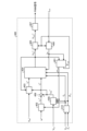
- FIG. 1 is a diagram showing a configuration example of a power conversion device 1 according to Embodiment 1.
- the power converter 1 is connected to a commercial power source 110 and a compressor 315 .
- the commercial power supply 110 is an example of an AC power supply
- the compressor 315 is an example of the equipment referred to in the first embodiment.
- a motor 314 is mounted on the compressor 315 .
- a motor drive device 2 is configured by the power conversion device 1 and the motor 314 included in the compressor 315 .
- the power conversion device 1 includes a voltage detection unit 140, a zero cross detection unit 142, a reactor 120, a rectification unit 130, current detection units 501 and 502, a voltage detection unit 503, a smoothing unit 200, an inverter 310, It includes current detection units 313 a and 313 b and a control unit 400 .
- Reactor 120 is connected between commercial power supply 110 and rectifying section 130 .
- the rectifying section 130 has a bridge circuit composed of rectifying elements 131-134.
- Rectifier 130 rectifies power supply voltage Vin applied from commercial power supply 110 and outputs the rectified power supply voltage.
- the rectifier 130 performs full-wave rectification.
- the smoothing section 200 is connected to the output terminal of the rectifying section 130 .
- Smoothing section 200 has capacitor 210 as a smoothing element, and smoothes the rectified voltage output from rectifying section 130 .
- the capacitor 210 is, for example, an electrolytic capacitor, a film capacitor, or the like. Capacitor 210 is connected to the output terminal of rectifying section 130 . Capacitor 210 has a capacity corresponding to the degree of smoothing the rectified voltage. Due to this smoothing, the voltage generated in the capacitor 210 does not have a full-wave rectified waveform of the rectified voltage, but has a waveform in which a voltage ripple corresponding to the frequency of the commercial power supply 110 is superimposed on the DC component, and does not pulsate greatly. When the commercial power source 110 is single-phase, the main component of the voltage ripple frequency is twice the frequency of the power supply voltage Vin .
- the amplitude of the voltage ripple is determined by the capacitance of capacitor 210 .
- the amplitude of the voltage ripple is, for example, the voltage of the capacitor 210 pulsating in a range such that the maximum value of the voltage ripple is less than twice the minimum value.
- the voltage detection section 140 detects the power supply voltage V in and outputs the detected value of the detected power supply voltage V in to the control section 400 and the zero cross detection section 142 .
- Zero-cross detection section 142 generates a zero-cross signal Z c corresponding to power supply voltage V in and outputs the generated zero-cross signal Z c to control section 400 .
- the zero-cross signal Zc is, for example, a signal that outputs a "High” level when the power supply voltage Vin is positive, and a signal that outputs a "Low” level when the power supply voltage Vin is negative. Note that these levels may be reversed.
- the detected value of the power supply voltage Vin and the zero-cross signal Zc are input to the controller 400 .
- Current detector 501 detects rectified current I ⁇ b>1 flowing out from rectifier 130 and outputs the detected value of rectified current I ⁇ b>1 to controller 400 .
- Current detection unit 502 detects inverter input current I ⁇ b>2 that flows into inverter 310 and outputs a detected value of inverter input current I ⁇ b>2 to control unit 400 .
- Voltage detection unit 503 detects capacitor voltage Vdc , which is the voltage of capacitor 210 , and outputs the detected value of the detected capacitor voltage Vdc to control unit 400 .
- Voltage detection unit 503 can be used as a detection unit that detects the power state of capacitor 210 .
- the inverter 310 is connected to both ends of the smoothing section 200 , that is, the capacitor 210 .
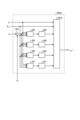
- the inverter 310 has switching elements 311a-311f and freewheeling diodes 312a-312f.
- the inverter 310 turns on and off the switching elements 311a to 311f under the control of the control unit 400, converts the DC power output from the rectifying unit 130 and the smoothing unit 200 into AC power having a desired amplitude and phase, and the motor 314 It outputs to the compressor 315 which is a mounted device.
- the current detection units 313 a and 313 b each detect the current value of one phase out of the three-phase motor currents output from the inverter 310 to the motor 314 .
- Each detection value of the current detection units 313 a and 313 b is input to the control unit 400 .
- the control unit 400 calculates the current of the remaining one phase based on the detected value of the current of any two phases detected by the current detection units 313a and 313b.
- a motor 314 mounted on the compressor 315 rotates according to the amplitude and phase of the AC power supplied from the inverter 310 to perform compression operation.
- the compressor 315 is a hermetic compressor used in an air conditioner or the like, the load torque of the compressor 315 can often be regarded as a constant torque load.
- FIG. 1 shows a case where the motor windings in the motor 314 are Y-connected
- the present invention is not limited to this example.
- the motor windings of the motor 314 may be delta-connection, or may be switchable between Y-connection and delta-connection.
- reactor 120 may be arranged after rectifying section 130 .
- the power conversion device 1 may include a booster section, or the rectifier section 130 may have the function of the booster section.
- the voltage detection unit 140 that detects the power supply voltage Vin is sometimes referred to as a "first detection unit”.
- At least one of the voltage detection unit 503 that detects the capacitor voltage Vdc , the current detection unit 501 that detects the rectified current I1, and the current detection unit 502 that detects the inverter input current I2 is referred to as the “second is sometimes referred to as the "detector of
- the control unit 400 acquires the detected value of the power supply voltage V in detected by the voltage detection unit 140 and the zero-cross signal Zc generated by the zero-cross detection unit 142 . Further, the control unit 400 detects the value of the rectified current I1 detected by the current detection unit 501, the value of the inverter input current I2 detected by the current detection unit 502, and the capacitor voltage V detected by the voltage detection unit 503. Get the detected value of dc . The control unit 400 also acquires the detected values of the motor currents detected by the current detection units 313a and 313b. Control unit 400 controls the operation of inverter 310, specifically, the on/off of switching elements 311a to 311f included in inverter 310, using the detection values detected by the respective detection units.
- control unit 400 controls the operation of the inverter 310 so that AC power including pulsation corresponding to the pulsation of the power flowing from the rectifying unit 130 into the capacitor 210 of the smoothing unit 200 is output from the inverter 310 to the compressor 315. do.
- the pulsation according to the pulsation of the power flowing into the capacitor 210 of the smoothing section 200 is, for example, the pulsation that varies depending on the frequency of the pulsation of the power flowing into the capacitor 210 of the smoothing section 200 .
- control unit 400 suppresses capacitor current I3, which is the charge/discharge current of capacitor 210 .
- the control unit 400 performs control so that any one of the speed, voltage, and current of the motor 314 is in a desired state. Note that the control unit 400 does not have to use all the detection values acquired from each detection unit, and can perform control using some of the detection values.
- the control unit 400 controls the motor 314 without a position sensor.
- position sensorless control methods for the motor 314 There are two types of position sensorless control methods for the motor 314: primary magnetic flux constant control and sensorless vector control. Embodiment 1 will be described based on sensorless vector control as an example. It should be noted that the control method described below can be applied to the primary magnetic flux constant control with minor modifications.
- the rectified current I1 flowing out of the rectifier 130 is affected by the power phase of the commercial power supply 110, the characteristics of elements installed before and after the rectifier 130, and the like.
- the rectified current I1 has characteristics including the power supply frequency and harmonic components of the power supply frequency.
- the power supply frequency is the frequency of the power supply voltage Vin .
- the harmonic component of the power supply frequency is dominant twice the power supply frequency.
- the harmonic component of the power supply frequency becomes dominant six times.
- the control unit 400 controls the inverter 310 so that the inverter input current I2 becomes equal to the rectified current I1, and controls the capacitor current I3 to approach zero. This suppresses deterioration of the capacitor 210 .
- a ripple component caused by PWM Pulse Width Modulation
- control unit 400 needs to control inverter 310 with the ripple component taken into consideration.
- Control unit 400 controls inverter 310 so that a value obtained by removing PWM ripple from inverter input current I2 from capacitor 210 to inverter 310 matches rectified current I1, and adds pulsation to the power output to motor 314 .
- Control unit 400 appropriately pulsates inverter input current I2 to perform pulsation compensation control to reduce pulsation of capacitor current I3.
- control unit 400 performs pulsation compensation control on capacitor 210 .
- Ripple compensation control is compensation control performed to suppress a pulsating component contained in capacitor current I3.
- Ripple compensation control is based on at least one detected value of rectified current I1, inverter input current I2, capacitor current I3, power supply voltage Vin , and capacitor voltage Vdc , which is information for grasping the power state of capacitor 210. can be implemented based on Due to the pulsation compensation control, the motor 314 is supplied with a current containing a pulsation component that is twice the power supply frequency (when the commercial power supply 110 is single-phase) or six times (when the commercial power supply 110 is three-phase). That is, due to the pulsation compensation control, a current containing a pulsation component with a frequency obtained by multiplying the power supply frequency by a specific integer flows through the motor 314 .
- FIG. 2 is a block diagram showing a configuration example of the control unit 400 included in the power converter 1 according to Embodiment 1.
- the control unit 400 includes a rotor position estimation unit 401, a speed control unit 402, a flux-weakening control unit 403, a current control unit 404, coordinate conversion units 405 and 406, a PWM signal generation unit 407, a q-axis current A pulsation calculator 408 , an adder 409 , and a frequency and phase calculator 410 are provided.
- the rotor position estimation unit 401 calculates the dq-axis Estimate an estimated phase angle ⁇ est , which is the direction at , and an estimated speed ⁇ est , which is the rotor speed.
- the speed control unit 402 automatically adjusts the q-axis current command i q1 * so that the speed command ⁇ * and the estimated speed ⁇ est match.
- the speed command ⁇ * is, for example, a temperature detected by a temperature sensor (not shown) or a setting indicated by a remote control that is an operation unit (not shown). It is based on information indicating temperature, operation mode selection information, operation start and operation end instruction information, and the like.
- the operation modes are, for example, heating, cooling, and dehumidification.
- the flux-weakening control unit 403 automatically adjusts the d-axis current command i d * so that the absolute value of the dq-axis voltage command vector V dq * falls within the limits of the voltage limit value V lim * . Further, in Embodiment 1, the flux-weakening control unit 403 performs flux-weakening control in consideration of the q-axis current ripple command i qrip * calculated by the q-axis current ripple calculation unit 408 .
- the flux-weakening control can be broadly divided into a method of calculating the d-axis current command id * from the equation of the voltage limit ellipse, and a method in which the absolute value deviation between the voltage limit value Vlim * and the dq-axis voltage command vector Vdq * is zero. There are two methods of calculating the d-axis current command i d * so that
- Frequency and phase calculator 410 calculates power supply frequency f in and power supply phase ⁇ in based on the detected value of power supply voltage V in detected by voltage detector 140 and zero-cross signal Z c generated by zero-cross detector 142 . to calculate The power supply frequency f in is the frequency of the power supply voltage Vin , and the power supply phase ⁇ in is the phase of the power supply voltage Vin .
- the power frequency f in and the power phase ⁇ in calculated by the frequency and phase calculator 410 may be referred to as the “detected value of the power frequency f in ” and the “detected value of the power phase ⁇ in ”, respectively. be.
- the current control unit 404 converts the dq-axis current vector idq into the d-axis current command id * and the q-axis current command iq based on the power supply frequency f in and the power supply phase ⁇ in calculated by the frequency and phase calculation unit 410 .
- the dq-axis voltage command vector V dq * is automatically adjusted so as to follow * .
- the coordinate conversion unit 405 coordinates-converts the dq-axis voltage command vector V dq * from the dq coordinates into the voltage command V uvw * of the AC quantity according to the estimated phase angle ⁇ est .
- a coordinate transformation unit 406 coordinates-transforms the current I uvw flowing through the motor 314 from an alternating current quantity to a dq-axis current vector i dq of dq coordinates in accordance with the estimated phase angle ⁇ est .
- the control unit 400 controls the two-phase current values detected by the current detection units 313a and 313b among the three-phase current values output from the inverter 310 for the current Iuvw flowing through the motor 314, It can be obtained by calculating the current value of the remaining one phase using the current values of the two phases.
- PWM signal generation unit 407 generates a PWM signal based on voltage command V uvw * coordinate-transformed by coordinate transformation unit 405 .
- Control unit 400 applies a voltage to motor 314 by outputting the PWM signal generated by PWM signal generation unit 407 to switching elements 311 a to 311 f of inverter 310 .
- a q-axis current ripple calculation unit 408 calculates the power supply frequency f in and the power supply phase ⁇ in calculated by the frequency and phase calculation unit 410, the detected value of the capacitor voltage V dc detected by the voltage detection unit 503, and the estimated speed ⁇ est q-axis current pulsation command i qrip * is calculated based on.
- An addition unit 409 adds the q-axis current command i q1 * output from the speed control unit 402 and the q-axis current ripple command i qrip * calculated by the q-axis current ripple calculation unit 408, and the calculated value is A certain q-axis current command i q * is output as a torque current command to the current control unit 404 .
- FIG. 3 is a diagram showing a configuration example of the q-axis current ripple calculator 408 included in the controller 400 according to the first embodiment.
- the q-axis current pulsation calculator 408 is configured as a feedback controller with a command value of zero. Generally, feedback controllers have a lower control response than feedforward controllers and are unsuitable for suppressing high-frequency pulsations, but various high-frequency pulsation suppression means have been proposed in the past. Famous methods include a method using Fourier coefficient calculation and a PID (Proportional Integral Differential) controller.
- the q-axis current pulsation calculator 408 includes a subtractor 383 , Fourier coefficient calculators 384 to 387 , PID controllers 388 to 391 , and an AC restorer 392 .
- the subtractor 383 calculates the deviation between the zero command value and the capacitor voltage Vdc .
- Fourier coefficient calculators 384 to 387 assume that the power supply frequency is the 1f component, and calculate the amplitudes of the sin2f component, cos2f component, sin4f component, and cos4f component included in the deviation.
- the detected signals multiplied by the Fourier coefficient calculators 384 to 387 are sin2(2 ⁇ f in t+ ⁇ in ), cos2(2 ⁇ f int + ⁇ in ), sin4(2 ⁇ f int + ⁇ in ), using time t and power supply frequency f in , respectively. and cos4(2 ⁇ f in t+ ⁇ in ).
- the detected signal has amplitudes of sin2f component, cos2f component, sin4f component, and cos4f component whose deviation includes twice the average value of the product of the input signal and the detected signal.
- the Fourier coefficient calculators 384 to 387 calculate the amplitude of the component corresponding to the power supply frequency f in of the commercial power supply 110 included in the deviation between the detected value and the command value. If the capacitor current I3 has a periodic waveform, the output signals of the Fourier coefficient calculators 384 to 387 are substantially constant.
- the PID control units 388 to 391 perform proportional-integral-derivative control, that is, PID control, so that specific frequency components of these deviations are zero.
- the proportional gain and the derivative gain can be zero, but the value of the integral gain must be non-zero in order to converge the deviation to zero. Therefore, in the PID controllers 388 to 391, integral action is the main function. Since the output of the integral control normally changes gently, the outputs of the PID control units 388 to 391 can also be regarded as substantially constant.
- the capacitor voltage Vdc is obtained by dividing the electric charge accumulated in the capacitor current I3, that is, the integrated value of the capacitor current I3, by the capacitance of the capacitor 210.
- the detection signals multiplied by the Fourier coefficient calculators 384 to 387 are sin2(2 ⁇ f in t+ ⁇ in ), cos2(2 ⁇ f in t+ ⁇ in ), sin4(2 ⁇ f in t+ ⁇ in ), and cos4(2 ⁇ f in ), respectively, as described above. t+ ⁇ in ).
- the AC restoration unit 392 shifts the restoration signal by the phase difference ⁇ offset to restore the outputs of the PID control units 388 to 391 to AC components . + ⁇ offset ), sin4(2 ⁇ f int + ⁇ in + ⁇ offset ), and cos4(2 ⁇ f int + ⁇ in + ⁇ offset ) and then summed to determine the q-axis current ripple command i qrip * .
- the AC restoring unit 392 generates the q-axis current pulsation command i qrip * , which is a pulsation command for suppressing the capacitor current I3.
- the case where the sensorless vector control method is used is exemplified, but if some modifications are made to add pulsation to the speed command, voltage command, etc., it can also be applied to the primary magnetic flux constant control.
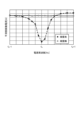
- FIG. 4 is a diagram showing an example of the relationship between the smoothing section pulsating current and the power supply frequency f in in the power converter 1 according to the first embodiment.
- the smoothing section pulsating current shown on the vertical axis is the effective value or average value of the pulsating component contained in the capacitor current I3, which is the current flowing through the smoothing section 200 .
- the horizontal axis of FIG. 4 represents the power supply frequency f in .
- the plots connected by solid lines represent the smooth section pulsating current when the pulsation compensation control function of the q-axis current pulsation calculator 408 is not activated, and the plots connected by broken lines represent q It represents the smoothing section pulsating current when the pulsation compensation control function of the shaft current pulsation calculating section 408 is activated.
- the characteristic shown in FIG. 4 is that, inside the control unit 400, the pulsation compensation control process is performed on the premise that the frequency of the commercial power supply 110 does not change, that is, the frequency used in the pulsation compensation control is constant fA . is assumed.
- the control unit 400 in an environment where the power supply frequency f in fluctuates greatly, it is effective to match the frequency f A used in the pulsation compensation control to the actual power supply frequency f in . Therefore, in the control unit 400 according to Embodiment 1, the power supply frequency f in and the power supply phase ⁇ in are calculated by the frequency and phase calculation unit 410, and the calculated power supply frequency f in and the power supply phase ⁇ in are calculated on the q-axis. It is configured to be input to the current pulsation calculator 408 .
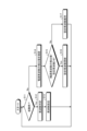
- FIG. 5 is a flowchart for explaining the frequency setting process performed inside the control unit 400 according to the first embodiment.
- the control unit 400 determines whether the current status is startup (step S11). If the control unit 400 is starting up (step S11, Yes), the control unit 400 determines the frequency of the commercial power supply 110 (step S12), and sets the determined frequency as the set frequency (step S13). For example, if the place of use of the power conversion device 1 is Japan, it is determined whether the frequency of the commercial power supply 110 is 50 [Hz] or 60 [Hz], and 50 [Hz] or 60 [Hz] is the initial value of the set frequency. Note that the above-described pulsation compensation control is performed based on this set frequency.
- step S11 if the current status is not startup (step S11, No), the control unit 400 checks the detected value of the power supply frequency f in (step S14), and further checks the detected value of the power supply frequency f in . and the set frequency is compared with a threshold value B (step S15).
- step S15 If the absolute value of the difference between the detected value of the power supply frequency f in and the set frequency exceeds the threshold value B (step S15, Yes), the set frequency is changed (step S16). In the process of step S16, the detected value of the power supply frequency f in confirmed in step S14 is used as a new set frequency. On the other hand, if the absolute value of the difference between the detected value of the power supply frequency f in and the set frequency does not exceed the threshold value B (step S15, No), the current set frequency is maintained (step S17).
- an appropriate power supply frequency f in can be set according to the environmental conditions of the power converter 1 . This makes it possible to enhance the effect of the pulsation compensation control in the power converter 1 .
- the set frequency is changed by comparing the detected value of the power supply frequency f in with the set frequency, but the processing is not limited to this. Instead of the set frequency, the set frequency may be changed by comparing the past detected value of the power supply frequency f in .
- the past detection value may be an average value of a plurality of detection values obtained in the past, or may be a detection value obtained through filtering such as a low-pass filter.
- the power converter 1 operates under the control by the control unit 400 described above, and the features of the operation are as follows.
- the power conversion device 1 calculates the absolute value of the difference between the frequency of the dominant pulsating component contained in the capacitor voltage Vdc or the capacitor current I3 and the frequency obtained by multiplying the detected value of the power supply frequency f in by a specific integer. It operates so that a certain first difference frequency is within 1 [Hz]. By operating in this way, the effect of the pulsation compensation control in the power converter 1 can be enhanced.
- the threshold value B used in step S15 of FIG. 5 should be appropriately set. As can be understood from the characteristics shown in FIG.
- the threshold B is a value smaller than 1 [Hz].
- the first difference frequency is the absolute value of the difference between the detected value of the power supply frequency f in and the frequency obtained by multiplying a specific integer, and the specific integer is 2 or 6, for example. , 0.5 [Hz].
- the threshold value B should be changed depending on whether the commercial power supply 110 is single-phase or three-phase.
- the power conversion device 1 is configured so that the second difference frequency, which is the absolute value of the difference between the frequency of the dominant pulsating component contained in the motor current flowing through the motor 314 and the set frequency, is within 1 [Hz]. works. By operating in this way, the effect of the pulsation compensation control in the power converter 1 can be enhanced.
- the threshold value B used in step S15 of FIG. 5 should be appropriately set. Points to consider when appropriately setting the threshold B are as described above.
- the power converter 1 When the function of pulsation compensation control in Embodiment 1 is working effectively, the power converter 1 operates so that the first or second differential frequency changes depending on the operating conditions of the equipment. become. If the example of the device is a compressor, the target values for the suction pressure, discharge pressure, refrigerant temperature, indoor temperature of the air conditioner, etc. of the compressor 315 correspond to the operating conditions referred to here. By confirming the change in the first or second difference frequency when at least one of these operating conditions is changed, it is possible to determine whether the function of the pulsation compensation control in the power converter 1 is normal. can be judged.
- FIG. 6 is a block diagram showing an example of a hardware configuration that implements the functions of the control unit 400 according to the first embodiment.
- FIG. 7 is a block diagram showing another example of the hardware configuration that implements the functions of the control unit 400 according to the first embodiment.
- the configuration may include an interface 424 .
- the processor 420 is an example of computing means.
- the processor 420 may be a computing means called a microprocessor, microcomputer, CPU (Central Processing Unit), or DSP (Digital Signal Processor).
- the memory 422 includes nonvolatile or volatile semiconductor memories such as RAM (Random Access Memory), ROM (Read Only Memory), flash memory, EPROM (Erasable Programmable ROM), EEPROM (registered trademark) (Electrically EPROM), Magnetic discs, flexible discs, optical discs, compact discs, mini discs, and DVDs (Digital Versatile Discs) can be exemplified.
- the memory 422 stores programs for executing the functions of the control unit 400 .
- the processor 420 can perform the above-described processing by exchanging necessary information via the interface 424 and executing the program stored in the memory 422 by the processor 420 . Results of operations by processor 420 may be stored in memory 422 .
- the processor 420 and memory 422 shown in FIG. 6 may be replaced with a processing circuit 423 as shown in FIG.
- the processing circuit 423 corresponds to a single circuit, a composite circuit, an ASIC (Application Specific Integrated Circuit), an FPGA (Field-Programmable Gate Array), or a combination thereof.
- Information to be input to the processing circuit 423 and information to be output from the processing circuit 423 can be obtained via the interface 424 .
- part of the processing in the control unit 400 may be performed by the processing circuit 423 and the processing not performed by the processing circuit 423 may be performed by the processor 420 and the memory 422 .
- the power converter according to Embodiment 1 performs pulsation compensation control to suppress the pulsation component of the capacitor current, which is the charge/discharge current of the capacitor, based on the detected value of the power supply voltage.
- the ripple change in the capacitor voltage can be reduced, so deterioration of the capacitor can be suppressed.
- the ripple change of the capacitor voltage can be reduced without increasing the capacitance of the capacitor, it is possible to suppress the deterioration of the capacitor and to suppress the enlargement of the device.
- the power converter according to Embodiment 1 calculates the power supply frequency based on the detected value of the power supply voltage and uses it as the detected value of the power supply frequency, and based on the set frequency set based on this detected value pulsation compensation control. That is, the power converter according to Embodiment 1 is configured so that the frequency used in the pulsation compensation control can be changed, so even in an environment where the power supply frequency fluctuates greatly, the effect of reducing the pulsating current in the smoothing section can be achieved. It can be held high.
- the frequency used in the pulsation compensation control can be changed, even if the type of commercial power supply is different, the design change of the control unit can be kept to a necessary minimum. This makes it possible to suppress an increase in manufacturing costs.
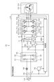
- FIG. 8 is a diagram showing a configuration example of a power conversion device 1A according to Embodiment 2.
- the controller 400 is replaced with a controller 400A.
- 2 A of motor drive apparatuses are comprised by 1 A of power converters, and the motor 314 with which the compressor 315 is provided.
- a current detection unit 504 that detects the capacitor current I3 is added to the power converter 1A.
- the detected value of capacitor current I3 detected by current detection unit 504 is input to control unit 400A.
- Other configurations are the same as or equivalent to those of the power conversion device 1 shown in FIG. 1, and the same or equivalent components are denoted by the same reference numerals, and overlapping descriptions are omitted.
- the current detection unit 504 that detects the capacitor current I3 is replaced with the voltage detection unit 503 that detects the capacitor voltage Vdc , the current detection unit 501 that detects the rectified current I1, and the current detection unit that detects the inverter input current I2. Together with the unit 502, it may be called a “second detection unit”.
- FIG. 9 is a block diagram showing a configuration example of a control section 400A included in the power converter 1A according to Embodiment 2. As shown in FIG. In a control unit 400A shown in FIG. 9, the q-axis current ripple calculation unit 408 is replaced with a q-axis current ripple calculation unit 408A as compared with the control unit 400 shown in FIG. The detected value of the capacitor current I3 is input to the q-axis current pulsation calculator 408A.
- Other configurations are the same as or equivalent to those of the control unit 400 shown in FIG. 2, and the same or equivalent components are denoted by the same reference numerals, and redundant description is omitted.
- FIG. 10 is a diagram showing a configuration example of a q-axis current pulsation calculation section 408A included in the control section 400A according to the second embodiment.
- the AC restoration section 392 is replaced with an AC restoration section 392A as compared with the q-axis current ripple calculation section 408 shown in FIG.
- the detection value of the capacitor current I3 is input to the subtraction unit 383 .
- the phase difference ⁇ offset that was used as the input signal to the AC restoration section 392 is deleted.
- Other configurations are the same as or equivalent to the q-axis current pulsation calculation unit 408 shown in FIG.
- the subtraction unit 383 calculates the deviation between the zero command value and the detected value of the capacitor current I3.
- Fourier coefficient calculators 384 to 387 calculate the amplitude of the component corresponding to power supply frequency f in of commercial power supply 110 included in the deviation between the detected value and the command value, as in the first embodiment.
- PID controllers 388-391 perform PID control so that specific frequency components of these deviations become zero.
- the AC restorer 392A restores the outputs of the PID controllers 388 to 391 to AC components by sin2(2 ⁇ f int + ⁇ in ), cos2( 2 ⁇ f int+ ⁇ in ), sin4(2 ⁇ f int + ⁇ in ), and cos4 After multiplying by (2 ⁇ f in t+ ⁇ in ), addition is performed to determine the q-axis current ripple command i qrip * .
- the AC restoring unit 392A generates the q-axis current pulsation command i qrip * , which is a pulsation command for suppressing the capacitor current I3.
- Other operations are the same as those in the first embodiment, and overlapping descriptions are omitted.
- the detected value of the capacitor current I3 is used to calculate the q-axis current ripple command i qrip * .
- the processing can be simpler than the processing of the current ripple calculation unit 408 . Therefore, the calculation load on the processor 420 or the processing circuit 423 can be reduced. As a result, the effect of facilitating task design in the processor 420 or the processing circuit 423 can be obtained while enjoying the effects of the first embodiment.
- Capacitor current I3 may be calculated from the value of rectified current I1 detected by current detection section 501 and the value of inverter input current I2 detected by current detection section 502 . Even in this way, the effects of the above-described second embodiment can be obtained.
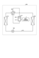
- FIG. 11 is a diagram showing a configuration example of a refrigeration cycle equipment 900 according to Embodiment 3.
- a refrigerating cycle applied equipment 900 according to the third embodiment includes the power converter 1 described in the first embodiment.
- the refrigerating cycle applied equipment 900 according to Embodiment 3 can be applied to products equipped with a refrigerating cycle, such as air conditioners, refrigerators, freezers, and heat pump water heaters.
- constituent elements having functions similar to those of the first embodiment are assigned the same reference numerals as those of the first embodiment.
- Refrigerating cycle applied equipment 900 includes compressor 315 incorporating motor 314 according to Embodiment 1, four-way valve 902, indoor heat exchanger 906, expansion valve 908, and outdoor heat exchanger 910 with refrigerant pipe 912. attached through
- a compression mechanism 904 that compresses the refrigerant and a motor 314 that operates the compression mechanism 904 are provided inside the compressor 315 .
- the refrigeration cycle applied equipment 900 can perform heating operation or cooling operation by switching operation of the four-way valve 902 .
- the compression mechanism 904 is driven by a variable speed controlled motor 314 .
- the refrigerant is pressurized by the compression mechanism 904 and sent out through the four-way valve 902, the indoor heat exchanger 906, the expansion valve 908, the outdoor heat exchanger 910, and the four-way valve 902. Return to compression mechanism 904 .
- the refrigerant is pressurized by the compression mechanism 904 and sent through the four-way valve 902, the outdoor heat exchanger 910, the expansion valve 908, the indoor heat exchanger 906, and the four-way valve 902. Return to compression mechanism 904 .
- the indoor heat exchanger 906 acts as a condenser to release heat, and the outdoor heat exchanger 910 acts as an evaporator to absorb heat.
- the outdoor heat exchanger 910 acts as a condenser to release heat, and the indoor heat exchanger 906 acts as an evaporator to absorb heat.
- the expansion valve 908 reduces the pressure of the refrigerant to expand it.
- the refrigerating cycle applied equipment 900 according to Embodiment 3 has been described as including the power converter 1 described in Embodiment 1, it is not limited to this.
- the power conversion device 1A described in the second embodiment may be used, or a power conversion device other than the power conversion devices 1 and 1A may be used as long as the control method described in the first and second embodiments can be applied. .
Landscapes
- Engineering & Computer Science (AREA)
- Power Engineering (AREA)
- Control Of Ac Motors In General (AREA)
- Inverter Devices (AREA)
Abstract
電力変換装置(1)は、商用電源(110)から印加される電源電圧を整流する整流部(130)と、整流部(130)の出力端に接続されるコンデンサ(210)と、コンデンサ(210)から出力される直流電力を交流電力に変換して、モータ(314)が搭載された機器に出力するインバータ(310)と、電源電圧を検出する電圧検出部(140)と、電圧検出部(140)の検出値に基づいてコンデンサ(210)の充放電電流であるコンデンサ電流の脈動成分を抑制する脈動補償制御を実施する制御部(400)とを備える。
Description
本開示は、交流電力を所望の電力に変換する電力変換装置、モータ駆動装置及び冷凍サイクル適用機器に関する。
従来、交流電源から供給される交流電力を所望の交流電力に変換し、空気調和機などの負荷に供給する電力変換装置がある。例えば、下記特許文献1には、空気調和機の制御装置である電力変換装置が、交流電源から供給される交流電力を整流部であるダイオードスタックで整流し、更に平滑コンデンサで平滑した電力を、複数のスイッチング素子からなるインバータで所望の交流電力に変換し、負荷である圧縮機モータに出力する技術が開示されている。
しかしながら、上記従来の技術によれば、平滑コンデンサに大きな脈動電流が流れるため、平滑コンデンサの経年劣化が加速するという問題があった。この問題に対して、平滑コンデンサの容量を大きくすることでコンデンサ電圧のリプル変化を抑制する、又はリプルによる劣化耐量の大きい平滑コンデンサを使用する方法が考えられる。しかしながら、このような方法では、コンデンサ部品のコストが高くなり、装置が大型化してしまうという問題がある。
本開示は、上記に鑑みてなされたものであって、平滑用のコンデンサの劣化を抑制しつつ、装置の大型化を抑制可能な電力変換装置を得ることを目的とする。
上述した課題を解決し、目的を達成するため、本開示に係る電力変換装置は、整流部と、整流部の出力端に接続されるコンデンサと、コンデンサの両端に接続されるインバータと、第1の検出部と、制御部とを備える。整流部は、交流電源から印加される電源電圧を整流する。インバータは、コンデンサから出力される直流電力を交流電力に変換して、モータが搭載された機器に出力する。第1の検出部は、電源電圧を検出する。制御部は、第1の検出部の検出値に基づいてコンデンサの充放電電流であるコンデンサ電流の脈動成分を抑制する脈動補償制御を実施する。
本開示に係る電力変換装置によれば、平滑用のコンデンサの劣化を抑制しつつ、装置の大型化を抑制できるという効果を奏する。
以下に添付図面を参照し、本開示の実施の形態に係る電力変換装置、モータ駆動装置及び冷凍サイクル適用機器について詳細に説明する。
実施の形態1.
図1は、実施の形態1に係る電力変換装置1の構成例を示す図である。図1において、電力変換装置1は、商用電源110及び圧縮機315に接続されている。商用電源110は交流電源の一例であり、圧縮機315は実施の形態1で言う機器の一例である。圧縮機315には、モータ314が搭載されている。電力変換装置1と、圧縮機315が備えるモータ314とによって、モータ駆動装置2が構成される。
図1は、実施の形態1に係る電力変換装置1の構成例を示す図である。図1において、電力変換装置1は、商用電源110及び圧縮機315に接続されている。商用電源110は交流電源の一例であり、圧縮機315は実施の形態1で言う機器の一例である。圧縮機315には、モータ314が搭載されている。電力変換装置1と、圧縮機315が備えるモータ314とによって、モータ駆動装置2が構成される。
電力変換装置1は、電圧検出部140と、ゼロクロス検出部142と、リアクトル120と、整流部130と、電流検出部501,502と、電圧検出部503と、平滑部200と、インバータ310と、電流検出部313a,313bと、制御部400と、を備える。
リアクトル120は、商用電源110と整流部130との間に接続される。整流部130は、整流素子131~134によって構成されるブリッジ回路を有する。整流部130は、商用電源110から印加される電源電圧Vinを整流して出力する。整流部130は、全波整流を行う。
平滑部200は、整流部130の出力端に接続される。平滑部200は、平滑素子としてコンデンサ210を有し、整流部130から出力される整流電圧を平滑化する。
コンデンサ210は、例えば電解コンデンサ、フィルムコンデンサなどである。コンデンサ210は、整流部130の出力端に接続される。コンデンサ210は、整流電圧を平滑化する程度に応じた容量を有する。この平滑化により、コンデンサ210に発生する電圧は、整流電圧の全波整流波形形状ではなく、直流成分に商用電源110の周波数に応じた電圧リプルが重畳した波形形状となり、大きく脈動しない。この電圧リプルの周波数は、商用電源110が単相の場合は電源電圧Vinの周波数の2倍成分が主成分となり、商用電源110が3相の場合は6倍成分が主成分となる。商用電源110から入力される電力、及びインバータ310から出力される電力が変化しない場合、電圧リプルの振幅はコンデンサ210の静電容量によって決まる。電圧リプルの振幅は、例えば、コンデンサ210の電圧は、電圧リプルの最大値が最小値の2倍未満となるような範囲で脈動する電圧となる。
電圧検出部140は、電源電圧Vinを検出し、検出した電源電圧Vinの検出値を制御部400及びゼロクロス検出部142に出力する。ゼロクロス検出部142は、電源電圧Vinに応じたゼロクロス信号Zcを生成し、生成したゼロクロス信号Zcを制御部400に出力する。ゼロクロス信号Zcは、例えば電源電圧Vinが正極性のときは“High”レベルを出力する信号であり、電源電圧Vinが負極性のときは“Low”レベルを出力する信号である。なお、これらのレベルは逆でもよい。電源電圧Vinの検出値及びゼロクロス信号Zcは、制御部400に入力される。
電流検出部501は、整流部130から流出する整流電流I1を検出し、検出した整流電流I1の検出値を制御部400に出力する。電流検出部502は、インバータ310に流入する電流であるインバータ入力電流I2を検出し、検出したインバータ入力電流I2の検出値を制御部400に出力する。電圧検出部503は、コンデンサ210の電圧であるコンデンサ電圧Vdcを検出し、検出したコンデンサ電圧Vdcの検出値を制御部400に出力する。電圧検出部503は、コンデンサ210の電力状態を検出する検出部として用いることができる。
インバータ310は、平滑部200、即ちコンデンサ210の両端に接続される。インバータ310は、スイッチング素子311a~311f、及び還流ダイオード312a~312fを有する。インバータ310は、制御部400の制御によってスイッチング素子311a~311fをオンオフし、整流部130及び平滑部200から出力される直流電力を所望の振幅及び位相を有する交流電力に変換して、モータ314が搭載された機器である圧縮機315に出力する。
電流検出部313a,313bは、各々がインバータ310からモータ314に出力される3相のモータ電流のうち1相の電流値を検出する。電流検出部313a,313bの各検出値は、制御部400に入力される。制御部400は、電流検出部313a,313bによって検出された何れか2相の電流の検出値に基づいて、残りの1相の電流を演算によって求める。
圧縮機315に搭載されるモータ314は、インバータ310から供給される交流電力の振幅及び位相に応じて回転し、圧縮動作を行う。圧縮機315が空気調和機などで使用される密閉型圧縮機の場合、圧縮機315の負荷トルクは、定トルク負荷とみなせる場合が多い。
なお、図1では、モータ314におけるモータ巻線がY結線の場合を示しているが、この例に限定されない。モータ314のモータ巻線は、Δ結線であってもよいし、Y結線とΔ結線とが切り替え可能な仕様であってもよい。
また、電力変換装置1において、図1に示す各部の構成及び配置は一例であり、各部の構成及び配置は図1で示される例に限定されない。例えば、リアクトル120は、整流部130の後段に配置されてもよい。また、電力変換装置1は、昇圧部を備えてもよいし、整流部130に昇圧部の機能を持たせるようにしてもよい。なお、本稿では、電源電圧Vinを検出する電圧検出部140を「第1の検出部」と呼ぶことがある。また、本稿では、コンデンサ電圧Vdcを検出する電圧検出部503、整流電流I1を検出する電流検出部501、及びインバータ入力電流I2を検出する電流検出部502のうちの少なくとも1つを「第2の検出部」と呼ぶことがある。
制御部400は、電圧検出部140で検出された電源電圧Vinの検出値、ゼロクロス検出部142で生成されたゼロクロス信号Zcを取得する。また、制御部400は、電流検出部501で検出された整流電流I1の検出値、電流検出部502で検出されたインバータ入力電流I2の検出値、及び電圧検出部503で検出されたコンデンサ電圧Vdcの検出値を取得する。また、制御部400は、電流検出部313a,313bで検出されたモータ電流の検出値を取得する。制御部400は、各々の検出部によって検出された検出値を用いて、インバータ310の動作、具体的には、インバータ310が有するスイッチング素子311a~311fのオンオフを制御する。
また、制御部400は、整流部130から平滑部200のコンデンサ210に流入する電力の脈動に応じた脈動を含む交流電力がインバータ310から圧縮機315に出力されるようにインバータ310の動作を制御する。平滑部200のコンデンサ210に流入する電力の脈動に応じた脈動とは、例えば、平滑部200のコンデンサ210に流入する電力の脈動の周波数などによって変動する脈動である。これにより、制御部400は、コンデンサ210の充放電電流であるコンデンサ電流I3を抑制する。制御部400は、モータ314の速度、電圧及び電流の何れかが所望の状態になるように制御を行う。なお、制御部400は、各検出部から取得した全ての検出値を用いなくてもよく、一部の検出値を用いて制御を行うことができる。
モータ314が圧縮機315の駆動用に使用され、圧縮機315が密閉型圧縮機の場合、モータ314に回転子位置を検出する位置センサを取り付けることが構造的にもコスト的にも困難なことが多い。このため、制御部400は、モータ314の制御を位置センサレスで行う。モータ314の位置センサレス制御方法については、一次磁束一定制御、及びセンサレスベクトル制御の2種類がある。実施の形態1では、一例として、センサレスベクトル制御をベースに説明する。なお、以降で説明する制御方法については、軽微な変更で一次磁束一定制御に適用することも可能である。
次に、制御部400における実施の形態1での特徴的な動作について説明する。まず、整流部130から流出する整流電流I1は、商用電源110の電源位相、整流部130の前後に設置される素子の特性などの影響を受ける。その結果、整流電流I1は、電源周波数及び電源周波数の高調波成分を含む特性を有する。電源周波数は、電源電圧Vinの周波数である。商用電源110が単相の場合、電源周波数の高調波成分は、電源周波数の2倍が支配的となる。また、商用電源110が3相の場合、電源周波数の高調波成分は、6倍が支配的となる。
また、コンデンサ210において、コンデンサ電流I3が大きいとコンデンサ210の経年劣化が加速する。特に、コンデンサ210として電解コンデンサを用いる場合、経年劣化の加速の度合いが大きくなる。そこで、制御部400は、インバータ入力電流I2が整流電流I1と等しくなるようにインバータ310を制御して、コンデンサ電流I3をゼロに近づける制御を行う。これにより、コンデンサ210の劣化が抑制される。但し、インバータ入力電流I2には、PWM(Pulse Width Modulation)に起因するリプル成分が重畳される。このため、制御部400は、リプル成分を加味してインバータ310を制御する必要がある。制御部400は、コンデンサ210からインバータ310へのインバータ入力電流I2からPWMリプルを除いた値が整流電流I1と一致するようにインバータ310を制御し、モータ314に出力される電力に脈動を加える。制御部400は、インバータ入力電流I2を適切に脈動させることによって、コンデンサ電流I3の脈動を減少させる脈動補償制御を行う。
以上のように、実施の形態1において、制御部400は、コンデンサ210に対して脈動補償制御を行う。脈動補償制御は、コンデンサ電流I3に含まれる脈動成分を抑制するために行う補償制御である。脈動補償制御は、コンデンサ210の電力状態を把握するための情報である、整流電流I1、インバータ入力電流I2、コンデンサ電流I3、電源電圧Vin及びコンデンサ電圧Vdcのうちの少なくとも1つの検出値に基づいて実施することができる。脈動補償制御によって、モータ314には、電源周波数の2倍(商用電源110が単相の場合)又は6倍(商用電源110が3相の場合)の脈動成分を含む電流が流れる。即ち、脈動補償制御によって、モータ314には、電源周波数に特定の整数を乗算した周波数の脈動成分を含む電流が流れる。
次に、上述した機能を実現する制御部400の構成について説明する。図2は、実施の形態1に係る電力変換装置1が備える制御部400の構成例を示すブロック図である。制御部400は、回転子位置推定部401と、速度制御部402と、弱め磁束制御部403と、電流制御部404と、座標変換部405,406と、PWM信号生成部407と、q軸電流脈動演算部408と、加算部409と、周波数及び位相演算部410と、を備える。
回転子位置推定部401は、モータ314を駆動するためのdq軸電圧指令ベクトルVdq
*及びdq軸電流ベクトルidqを用いて、モータ314が有する図示しない回転子について、回転子磁極のdq軸での方向である推定位相角θest、及び回転子速度である推定速度ωestを推定する。
速度制御部402は、速度指令ω*と推定速度ωestとが一致するようにq軸電流指令iq1
*を自動調整する。速度指令ω*は、電力変換装置1が冷凍サイクル適用機器として空気調和機などに使用される場合、例えば、図示しない温度センサで検出された温度、図示しない操作部であるリモコンから指示される設定温度を示す情報、運転モードの選択情報、運転開始及び運転終了の指示情報などに基づくものである。運転モードとは、例えば、暖房、冷房、除湿などである。
弱め磁束制御部403は、dq軸電圧指令ベクトルVdq
*の絶対値が電圧リミット値Vlim
*の制限値内に収まるようにd軸電流指令id
*を自動調整する。また、実施の形態1において、弱め磁束制御部403は、q軸電流脈動演算部408で演算されたq軸電流脈動指令iqrip
*を加味して弱め磁束制御を行う。弱め磁束制御は、大別して、電圧制限楕円の方程式からd軸電流指令id
*を計算する方法、及び電圧リミット値Vlim
*とdq軸電圧指令ベクトルVdq
*との絶対値の偏差がゼロになるようにd軸電流指令id
*を計算する方法の2種類があるが、どちらの方法を使用してもよい。
周波数及び位相演算部410は、電圧検出部140で検出された電源電圧Vinの検出値、及びゼロクロス検出部142で生成されたゼロクロス信号Zcに基づいて、電源周波数fin及び電源位相θinを演算する。電源周波数finは電源電圧Vinの周波数であり、電源位相θinは電源電圧Vinの位相である。なお、本稿では、周波数及び位相演算部410で演算された電源周波数fin及び電源位相θinを、それぞれ「電源周波数finの検出値」及び「電源位相θinの検出値」と呼ぶことがある。
電流制御部404は、周波数及び位相演算部410で演算された電源周波数fin及び電源位相θinに基づいて、dq軸電流ベクトルidqがd軸電流指令id
*及びq軸電流指令iq
*に追従するようにdq軸電圧指令ベクトルVdq
*を自動調整する。
座標変換部405は、推定位相角θestに応じて、dq軸電圧指令ベクトルVdq
*をdq座標から交流量の電圧指令Vuvw
*に座標変換する。
座標変換部406は、推定位相角θestに応じて、モータ314に流れる電流Iuvwを交流量からdq座標のdq軸電流ベクトルidqに座標変換する。前述のように、制御部400は、モータ314に流れる電流Iuvwについて、インバータ310から出力される3相の電流値のうち、電流検出部313a,313bで検出される2相の電流値、及び2相の電流値を用いて残りの1相の電流値を算出することによって取得することができる。
PWM信号生成部407は、座標変換部405で座標変換された電圧指令Vuvw
*に基づいてPWM信号を生成する。制御部400は、PWM信号生成部407で生成されたPWM信号をインバータ310のスイッチング素子311a~311fに出力することで、モータ314に電圧を印加する。
q軸電流脈動演算部408は、周波数及び位相演算部410で演算された電源周波数fin及び電源位相θin、電圧検出部503で検出されたコンデンサ電圧Vdcの検出値、並びに推定速度ωestに基づいて、q軸電流脈動指令iqrip
*を演算する。
加算部409は、速度制御部402から出力されたq軸電流指令iq1
*と、q軸電流脈動演算部408で演算されたq軸電流脈動指令iqrip
*とを加算し、その演算値であるq軸電流指令iq
*を電流制御部404へのトルク電流指令として出力する。
図3は、実施の形態1に係る制御部400が備えるq軸電流脈動演算部408の構成例を示す図である。q軸電流脈動演算部408は、指令値をゼロとしたフィードバック制御器として構成される。通常、フィードバック制御器は、フィードフォワード制御器と比較して制御応答が低く、高周波の脈動を抑制するには不向きであるが、様々な高周波脈動抑制手段が過去に提案されている。有名な方法としては、フーリエ係数演算及びPID(Proportional Integral Differential)制御器を用いた手法がある。q軸電流脈動演算部408は、減算部383と、フーリエ係数演算部384~387と、PID制御部388~391と、交流復元部392と、を備える。
減算部383は、ゼロである指令値と、コンデンサ電圧Vdcとの偏差を計算する。フーリエ級数展開の理論を用いれば、偏差に含まれる特定周波数のsin信号成分及びcos信号成分の振幅を抽出することが可能である。フーリエ係数演算部384~387は、電源周波数が1f成分であるとして、偏差に含まれるsin2f成分、cos2f成分、sin4f成分、及びcos4f成分の振幅をそれぞれ計算する。フーリエ係数演算部384~387で乗じられる検波信号は、時間t及び電源周波数finを用いて、それぞれsin2(2πfint+θin)、cos2(2πfint+θin)、sin4(2πfint+θin)、及びcos4(2πfint+θin)で表される。また、この検波信号は、入力信号と検波信号との積の平均値の2倍がそれぞれ偏差に含まれるsin2f成分、cos2f成分、sin4f成分、及びcos4f成分の振幅である。即ち、フーリエ係数演算部384~387は、検出値と指令値との偏差に含まれる、商用電源110の電源周波数finに応じた成分の振幅を演算する。コンデンサ電流I3が周期波形であれば、フーリエ係数演算部384~387の出力信号はほぼ一定となる。
PID制御部388~391は、これらの偏差の特定の周波数成分がそれぞれゼロになるように比例-積分-微分制御、即ちPID制御を実施する。比例ゲイン及び微分ゲインはゼロでも構わないが、偏差をゼロに収束させるためには積分ゲインの値が非ゼロでなければならない。そのため、PID制御部388~391では、積分動作がメインとなる。通常、積分制御の出力は緩やかに変化するので、PID制御部388~391の出力も概ね一定と見なすことができる。
ここで、コンデンサ電圧Vdcは、コンデンサ電流I3に蓄積される電荷、即ちコンデンサ電流I3の積分値をコンデンサ210の静電容量で除算したものである。このため、コンデンサ電流I3とコンデンサ電圧Vdcとの間には90度の位相差がある。従って、交流復元部392は、90度の位相差を加味してq軸電流脈動指令iqrip
*を決定しなければならない。90度の位相差をθoffset(=π/2[rad])とした場合、交流復元部392は、以下のように復元演算を実施する。
まず、フーリエ係数演算部384~387で乗じられる検波信号は、前述の通り、それぞれsin2(2πfint+θin)、cos2(2πfint+θin)、sin4(2πfint+θin)、及びcos4(2πfint+θin)である。交流復元部392は、PID制御部388~391の出力を交流成分に復元すべく、位相差θoffsetの分だけ復元信号をシフトしたsin2(2πfint+θin+θoffset)、cos2(2πfint+θin+θoffset)、sin4(2πfint+θin+θoffset)、及びcos4(2πfint+θin+θoffset)と掛け合わせた後に合算して、q軸電流脈動指令iqrip
*を決定する。このようにして、交流復元部392は、コンデンサ電流I3を抑制するための脈動分の指令であるq軸電流脈動指令iqrip
*を生成する。
ここでは、センサレスベクトル制御方式を用いる場合について例示したが、多少の変形を加えて速度指令、電圧指令などに脈動を加える形にすれば、一次磁束一定制御にも適用が可能である。
図4は、実施の形態1に係る電力変換装置1における平滑部脈動電流と電源周波数finとの間の関係性の一例を示す図である。縦軸に示される平滑部脈動電流は、平滑部200に流れる電流であるコンデンサ電流I3に含まれる脈動成分の実効値又は平均値である。図4の横軸は、電源周波数finを表している。商用電源110の周波数が50[Hz]である場合、fA=50であり、商用電源110の周波数が60[Hz]である場合、fA=60である。また、図4において、実線で結ばれているプロットは、q軸電流脈動演算部408による脈動補償制御機能を働かせていない場合の平滑部脈動電流を表し、破線で結ばれているプロットは、q軸電流脈動演算部408による脈動補償制御機能を働かせている場合の平滑部脈動電流を表している。更に、図4示す特性は、制御部400の内部では、商用電源110の周波数が変化しないことを前提とした脈動補償制御の処理、即ち脈動補償制御で使用する周波数が不変のfAであることを想定している。
図4の特性を見ると、実際の電源周波数finが脈動補償制御で使用する周波数fA、若しくは周波数fAに近い値である場合、平滑部脈動電流の低減効果が高いことが分かる。一方、実際の電源周波数finと、脈動補償制御で使用する周波数fAとがずれている場合、そのずれ量に応じて、平滑部脈動電流の低減効果が低下していくことが分かる。但し、低減効果及びずれ量は、制御設定条件又は運転条件により変わるものであることは言うまでもない。また、図4によれば、実際の電源周波数finと、脈動補償制御で使用する周波数fAとの差が-1[Hz]になった場合には、脈動補償制御機能を働かせていない場合と同程度の低減効果しか得られないことが示されている。また、図4によれば、実際の電源周波数finと、脈動補償制御で使用する周波数fAとの差が+1[Hz]になった場合には、脈動補償制御機能を働かせていない場合よりも悪化することが示されている。
以上のことから、電源周波数finの変動が大きい環境においては、脈動補償制御で使用する周波数fAを実際の電源周波数finに合わせることが効果的である。このため、実施の形態1に係る制御部400においては、電源周波数fin及び電源位相θinを周波数及び位相演算部410で演算すると共に、演算した電源周波数fin及び電源位相θinをq軸電流脈動演算部408に入力する構成としている。
図5は、実施の形態1に係る制御部400の内部で行われる周波数設定処理の説明に供するフローチャートである。
まず、制御部400は、現在のステータスが、起動時であるか否かを判定する(ステップS11)。制御部400は、起動時であれば(ステップS11,Yes)、商用電源110の周波数を判定し(ステップS12)、判定した周波数を設定周波数とする(ステップS13)。例えば、電力変換装置1の使用場所が日本国であれば、商用電源110の周波数が50[Hz]であるか、60[Hz]であるかが判定され、50[Hz]又は60[Hz]の何れかが設定周波数の初期値とされる。なお、上述した脈動補償制御は、この設定周波数に基づいて実施される。
ステップS11に戻り、現在のステータスが、起動時ではない場合(ステップS11,No)、制御部400は、電源周波数finの検出値を確認し(ステップS14)、更に電源周波数finの検出値と設定周波数との差の絶対値を閾値Bと比較する(ステップS15)。
電源周波数finの検出値と設定周波数との差の絶対値が閾値Bを超えている場合(ステップS15,Yes)、設定周波数を変更、即ち更新する(ステップS16)。このステップS16の処理では、ステップS14で確認された電源周波数finの検出値が新たな設定周波数とされる。一方、電源周波数finの検出値と設定周波数との差の絶対値が閾値Bを超えていない場合(ステップS15,No)、現在の設定周波数が維持される(ステップS17)。
図5のフローチャートに示す処理を実施すれば、電力変換装置1の環境条件に応じて、適切な電源周波数finを設定することができる。これにより、電力変換装置1における脈動補償制御の効果を高めることが可能となる。
なお、図5におけるステップS15,S16の処理では、電源周波数finの検出値を設定周波数と比較することで設定周波数を変更しているが、この処理に限定されない。設定周波数に代えて、電源周波数finの過去の検出値を比較対象とすることで、設定周波数を変更してもよい。過去の検出値は、過去に得られた複数回の検出値の平均値であってもよいし、ローパスフィルタ等のフィルタ処理を介した検出値であってもよい。
上述した制御部400による制御によって、実施の形態1に係る電力変換装置1は動作するが、その動作の特徴は以下の通りである。まず、電力変換装置1は、コンデンサ電圧Vdc又はコンデンサ電流I3に含まれる支配的な脈動成分の周波数と、電源周波数finの検出値に特定の整数を乗算した周波数との差の絶対値である第1の差分周波数が1[Hz]以内であるように動作する。このように動作すれば、電力変換装置1における脈動補償制御の効果を高めることができる。第1の差分周波数が1[Hz]以内であるように電力変換装置1を動作させるには、図5のステップS15で用いる閾値Bを適切に設定すればよい。図4に示す特性から理解できるように、閾値Bは1[Hz]よりも小さい値である。また、第1の差分周波数は、電源周波数finの検出値に特定の整数を乗算した周波数との差の絶対値であり、特定の整数は、例えば2又は6であることから、閾値Bは、0.5[Hz]よりも小さい値になる。なお、商用電源110が単相であるか3相であるかによって、閾値Bを変更すべきであることは言うまでも無い。
また、電力変換装置1は、モータ314に流れるモータ電流に含まれる支配的な脈動成分の周波数と、設定周波数との差の絶対値である第2の差分周波数が1[Hz]以内であるように動作する。このように動作すれば、電力変換装置1における脈動補償制御の効果を高めることができる。第2の差分周波数が1[Hz]以内であるように電力変換装置1を動作させるには、図5のステップS15で用いる閾値Bを適切に設定すればよい。閾値Bを適切に設定する際の着意事項は、前述の通りである。
なお、実施の形態1における脈動補償制御の機能が有効に作用している場合、電力変換装置1は、機器に対する運転条件によっても、第1又は第2の差分周波数が変化するように動作することになる。機器の例が圧縮機である場合、圧縮機315の吸入圧力、吐出圧力、冷媒の温度、空調機の室内温度の目標値などが、ここで言う運転条件に相当する。これらの運転条件のうちの少なくとも1つを変更した際の第1又は第2の差分周波数の変化を確認するようにすれば、電力変換装置1における脈動補償制御の機能が正常であるか否かを判断することができる。
次に、実施の形態1に係る制御部400の機能を実現するためのハードウェア構成について、図6及び図7の図面を参照して説明する。図6は、実施の形態1に係る制御部400の機能を実現するハードウェア構成の一例を示すブロック図である。図7は、実施の形態1に係る制御部400の機能を実現するハードウェア構成の他の例を示すブロック図である。
制御部400の機能の一部又は全部を実現するには、図6に示すように、演算を行うプロセッサ420、プロセッサ420によって読みとられるプログラムが保存されるメモリ422、及び信号の入出力を行うインタフェース424を含む構成とすることができる。
プロセッサ420は、演算手段の例示である。プロセッサ420は、マイクロプロセッサ、マイクロコンピュータ、CPU(Central Processing Unit)、又はDSP(Digital Signal Processor)と称される演算手段であってもよい。また、メモリ422には、RAM(Random Access Memory)、ROM(Read Only Memory)、フラッシュメモリ、EPROM(Erasable Programmable ROM)、EEPROM(登録商標)(Electrically EPROM)といった不揮発性又は揮発性の半導体メモリ、磁気ディスク、フレキシブルディスク、光ディスク、コンパクトディスク、ミニディスク、DVD(Digital Versatile Disc)を例示することができる。
メモリ422には、制御部400の機能を実行するプログラムが格納されている。プロセッサ420は、インタフェース424を介して必要な情報を授受し、メモリ422に格納されたプログラムをプロセッサ420が実行することにより、上述した処理を実行することができる。プロセッサ420による演算結果は、メモリ422に記憶することができる。
また、図6に示すプロセッサ420及びメモリ422は、図7のように処理回路423に置き換えてもよい。処理回路423は、単一回路、複合回路、ASIC(Application Specific Integrated Circuit)、FPGA(Field-Programmable Gate Array)、又は、これらを組み合わせたものが該当する。処理回路423に入力する情報、及び処理回路423から出力する情報は、インタフェース424を介して入手することができる。
なお、制御部400における一部の処理を処理回路423で実施し、処理回路423で実施しない処理をプロセッサ420及びメモリ422で実施してもよい。
以上説明したように、実施の形態1に係る電力変換装置は、電源電圧の検出値に基づいて、コンデンサの充放電電流であるコンデンサ電流の脈動成分を抑制する脈動補償制御を実施する。これにより、コンデンサ電圧のリプル変化を小さくできるので、コンデンサの劣化を抑制することができる。また、コンデンサの容量を大きくすることなく、コンデンサ電圧のリプル変化を小さくできるので、コンデンサの劣化を抑制しつつ、装置の大型化を抑制することができる。
また、電源周波数の変動が大きい環境において、脈動補償制御で使用する周波数を固定した状態で脈動補償制御を実施すると、平滑部脈動電流の低減効果が小さくなる。これに対し、実施の形態1に係る電力変換装置は、電源電圧の検出値に基づいて電源周波数を演算して電源周波数の検出値とすると共に、この検出値に基づいて設定した設定周波数に基づいて脈動補償制御を実施する。即ち、実施の形態1に係る電力変換装置は、脈動補償制御で使用する周波数が変更可能に構成されているので、電源周波数の変動が大きい環境であっても、平滑部脈動電流の低減効果を高い状態に保持することができる。また、脈動補償制御で使用する周波数が変更可能に構成されているので、商用電源の種類が異なる場合であっても、制御部の設計変更を必要最小限に留めることができる。これにより、製造コストの増加を抑制することが可能となる。
実施の形態2.
図8は、実施の形態2に係る電力変換装置1Aの構成例を示す図である。図8に示す電力変換装置1Aでは、制御部400が制御部400Aに置き替えられている。電力変換装置1Aと、圧縮機315が備えるモータ314とによって、モータ駆動装置2Aが構成される。また、電力変換装置1Aには、コンデンサ電流I3を検出する電流検出部504が追加されている。電流検出部504によって検出されたコンデンサ電流I3の検出値は、制御部400Aに入力される。その他の構成は、図1に示す電力変換装置1と同一又は同等であり、同一又は同等の構成部には同一の符号を付して示すと共に、重複する説明は割愛する。なお、本稿では、コンデンサ電流I3を検出する電流検出部504を、コンデンサ電圧Vdcを検出する電圧検出部503、整流電流I1を検出する電流検出部501、及びインバータ入力電流I2を検出する電流検出部502と共に「第2の検出部」と呼ぶことがある。
図8は、実施の形態2に係る電力変換装置1Aの構成例を示す図である。図8に示す電力変換装置1Aでは、制御部400が制御部400Aに置き替えられている。電力変換装置1Aと、圧縮機315が備えるモータ314とによって、モータ駆動装置2Aが構成される。また、電力変換装置1Aには、コンデンサ電流I3を検出する電流検出部504が追加されている。電流検出部504によって検出されたコンデンサ電流I3の検出値は、制御部400Aに入力される。その他の構成は、図1に示す電力変換装置1と同一又は同等であり、同一又は同等の構成部には同一の符号を付して示すと共に、重複する説明は割愛する。なお、本稿では、コンデンサ電流I3を検出する電流検出部504を、コンデンサ電圧Vdcを検出する電圧検出部503、整流電流I1を検出する電流検出部501、及びインバータ入力電流I2を検出する電流検出部502と共に「第2の検出部」と呼ぶことがある。
図9は、実施の形態2に係る電力変換装置1Aが備える制御部400Aの構成例を示すブロック図である。図9に示す制御部400Aでは、図2に示す制御部400と比較すると、q軸電流脈動演算部408がq軸電流脈動演算部408Aに置き替えられている。q軸電流脈動演算部408Aには、コンデンサ電流I3の検出値が入力される。その他の構成は、図2に示す制御部400と同一又は同等であり、同一又は同等の構成部には同一の符号を付して示すと共に、重複する説明は割愛する。
図10は、実施の形態2に係る制御部400Aが備えるq軸電流脈動演算部408Aの構成例を示す図である。図10に示すq軸電流脈動演算部408Aでは、図3に示すq軸電流脈動演算部408と比較すると、交流復元部392が交流復元部392Aに置き替えられている。また、減算部383には、コンデンサ電流I3の検出値が入力される。また、図10では、交流復元部392への入力信号とされていた位相差θoffsetが削除されている。その他の構成は、図3に示すq軸電流脈動演算部408と同一又は同等であり、同一又は同等の構成部には同一の符号を付して示すと共に、重複する説明は割愛する。
減算部383は、ゼロである指令値と、コンデンサ電流I3の検出値との偏差を計算する。フーリエ係数演算部384~387は、実施の形態1と同様に、検出値と指令値との偏差に含まれる、商用電源110の電源周波数finに応じた成分の振幅を演算する。PID制御部388~391は、これらの偏差の特定の周波数成分がそれぞれゼロになるようにPID制御を実施する。
ここで、実施の形態2では、コンデンサ電流I3の検出値を用いるので、実施の形態1では使用していた位相差θoffsetの情報は不要となる。従って、交流復元部392Aは、PID制御部388~391の出力を交流成分に復元すべく、sin2(2πfint+θin)、cos2(2πfint+θin)、sin4(2πfint+θin)、及びcos4(2πfint+θin)と掛け合わせた後に合算して、q軸電流脈動指令iqrip
*を決定する。このようにして、交流復元部392Aは、コンデンサ電流I3を抑制するための脈動分の指令であるq軸電流脈動指令iqrip
*を生成する。なお、その他の動作は実施の形態1と同様であり、重複する説明は割愛する。
実施の形態2によれば、コンデンサ電流I3の検出値を用いてq軸電流脈動指令iqrip
*を演算するので、q軸電流脈動演算部408Aの処理を、実施の形態1で説明したq軸電流脈動演算部408の処理よりも簡素化することができる。従って、プロセッサ420又は処理回路423における計算負荷を下げることが可能となる。これにより、実施の形態1の効果を享受しつつ、プロセッサ420又は処理回路423におけるタスク設計が容易になるという効果も得られる。
なお、実施の形態2では、コンデンサ電流I3を電流検出部504によって検出する構成を示したが、この構成に限定されない。コンデンサ電流I3は、電流検出部501によって検出された整流電流I1の検出値と、電流検出部502によって検出されたインバータ入力電流I2の検出値とによって演算で求めるようにしてもよい。このようにしても、上述した実施の形態2の効果を得ることができる。
実施の形態3.
図11は、実施の形態3に係る冷凍サイクル適用機器900の構成例を示す図である。実施の形態3に係る冷凍サイクル適用機器900は、実施の形態1で説明した電力変換装置1を備える。実施の形態3に係る冷凍サイクル適用機器900は、空気調和機、冷蔵庫、冷凍庫、ヒートポンプ給湯器といった冷凍サイクルを備える製品に適用することが可能である。なお、図11において、実施の形態1と同様の機能を有する構成要素には、実施の形態1と同一の符号を付している。
図11は、実施の形態3に係る冷凍サイクル適用機器900の構成例を示す図である。実施の形態3に係る冷凍サイクル適用機器900は、実施の形態1で説明した電力変換装置1を備える。実施の形態3に係る冷凍サイクル適用機器900は、空気調和機、冷蔵庫、冷凍庫、ヒートポンプ給湯器といった冷凍サイクルを備える製品に適用することが可能である。なお、図11において、実施の形態1と同様の機能を有する構成要素には、実施の形態1と同一の符号を付している。
冷凍サイクル適用機器900は、実施の形態1におけるモータ314を内蔵した圧縮機315と、四方弁902と、室内熱交換器906と、膨張弁908と、室外熱交換器910とが冷媒配管912を介して取り付けられている。
圧縮機315の内部には、冷媒を圧縮する圧縮機構904と、圧縮機構904を動作させるモータ314とが設けられている。
冷凍サイクル適用機器900は、四方弁902の切替動作により暖房運転又は冷房運転をすることができる。圧縮機構904は、可変速制御されるモータ314によって駆動される。
暖房運転時には、実線矢印で示すように、冷媒が圧縮機構904で加圧されて送り出され、四方弁902、室内熱交換器906、膨張弁908、室外熱交換器910及び四方弁902を通って圧縮機構904に戻る。
冷房運転時には、破線矢印で示すように、冷媒が圧縮機構904で加圧されて送り出され、四方弁902、室外熱交換器910、膨張弁908、室内熱交換器906及び四方弁902を通って圧縮機構904に戻る。
暖房運転時には、室内熱交換器906が凝縮器として作用して熱放出を行い、室外熱交換器910が蒸発器として作用して熱吸収を行う。冷房運転時には、室外熱交換器910が凝縮器として作用して熱放出を行い、室内熱交換器906が蒸発器として作用し、熱吸収を行う。膨張弁908は、冷媒を減圧して膨張させる。
なお、実施の形態3に係る冷凍サイクル適用機器900は、実施の形態1で説明した電力変換装置1を備えるものとして説明したが、これに限定されない。実施の形態2で説明した電力変換装置1Aを用いてもよいし、実施の形態1,2で説明した制御手法を適用できるものであれば、電力変換装置1,1A以外の電力変換装置でもよい。
以上の実施の形態に示した構成は、一例を示すものであり、別の公知の技術と組み合わせることも可能であるし、実施の形態同士を組み合わせることも可能であるし、要旨を逸脱しない範囲で、構成の一部を省略、変更することも可能である。
1,1A 電力変換装置、2,2A モータ駆動装置、110 商用電源、120 リアクトル、130 整流部、131~134 整流素子、140,503 電圧検出部、142 ゼロクロス検出部、200 平滑部、210 コンデンサ、310 インバータ、311a~311f スイッチング素子、312a~312f 還流ダイオード、313a,313b,501,502,504 電流検出部、314 モータ、315 圧縮機、383 減算部、384~387 フーリエ係数演算部、388~391 PID制御部、392,392A 交流復元部、400,400A 制御部、401 回転子位置推定部、402 速度制御部、403 弱め磁束制御部、404 電流制御部、405,406 座標変換部、407 PWM信号生成部、408,408A q軸電流脈動演算部、409 加算部、410 周波数及び位相演算部、420 プロセッサ、422 メモリ、423 処理回路、424 インタフェース、900 冷凍サイクル適用機器、902 四方弁、904 圧縮機構、906 室内熱交換器、908 膨張弁、910 室外熱交換器、912 冷媒配管。
Claims (9)
- 交流電源から印加される電源電圧を整流する整流部と、
前記整流部の出力端に接続されるコンデンサと、
前記コンデンサの両端に接続され、前記コンデンサから出力される直流電力を交流電力に変換して、モータが搭載された機器に出力するインバータと、
前記電源電圧を検出する第1の検出部と、
前記第1の検出部の検出値に基づいて前記コンデンサの充放電電流であるコンデンサ電流の脈動成分を抑制する脈動補償制御を実施する制御部と、
を備える電力変換装置。 - 前記脈動補償制御によって、前記モータには、前記電源電圧の周波数である電源周波数に特定の整数を乗算した周波数の脈動成分を含む電流が流れる
請求項1に記載の電力変換装置。 - 前記制御部は、前記第1の検出部の検出値に基づいて前記電源周波数を演算して前記電源周波数の検出値とし、
前記電源周波数の検出値に基づいて設定した設定周波数に基づいて前記脈動補償制御を実施する
請求項2に記載の電力変換装置。 - 前記設定周波数は、前記電源周波数の検出値と、過去に得られた複数回の前記電源周波数の検出値の平均値とに基づいて変更される
請求項3に記載の電力変換装置。 - 前記コンデンサ電流に含まれる支配的な脈動成分の周波数と前記電源周波数の検出値に特定の整数を乗算した周波数との差の絶対値である第1の差分周波数が1[Hz]以内である
請求項3又は4に記載の電力変換装置。 - 前記モータに流れるモータ電流に含まれる支配的な脈動成分の周波数と前記設定周波数との差の絶対値である第2の差分周波数が1[Hz]以内である
請求項3又は4に記載の電力変換装置。 - 前記機器に対する運転条件によって、前記コンデンサ電流に含まれる支配的な脈動成分の周波数と前記電源周波数の検出値に特定の整数を乗算した周波数との差の絶対値である第1の差分周波数、又は前記モータに流れるモータ電流に含まれる支配的な脈動成分の周波数と前記設定周波数との差の絶対値である第2の差分周波数のうちの少なくとも1つが変化する
請求項3から6の何れか1項に記載の電力変換装置。 - 請求項1から7の何れか1項に記載の電力変換装置を備えるモータ駆動装置。
- 請求項1から7の何れか1項に記載の電力変換装置を備える冷凍サイクル適用機器。
Priority Applications (3)
| Application Number | Priority Date | Filing Date | Title |
|---|---|---|---|
| JP2023565773A JPWO2023105676A1 (ja) | 2021-12-08 | 2021-12-08 | |
| PCT/JP2021/045109 WO2023105676A1 (ja) | 2021-12-08 | 2021-12-08 | 電力変換装置、モータ駆動装置及び冷凍サイクル適用機器 |
| CN202180104625.0A CN118339757A (zh) | 2021-12-08 | 2021-12-08 | 电力转换装置、马达驱动装置以及制冷循环应用设备 |
Applications Claiming Priority (1)
| Application Number | Priority Date | Filing Date | Title |
|---|---|---|---|
| PCT/JP2021/045109 WO2023105676A1 (ja) | 2021-12-08 | 2021-12-08 | 電力変換装置、モータ駆動装置及び冷凍サイクル適用機器 |
Publications (1)
| Publication Number | Publication Date |
|---|---|
| WO2023105676A1 true WO2023105676A1 (ja) | 2023-06-15 |
Family
ID=86729941
Family Applications (1)
| Application Number | Title | Priority Date | Filing Date |
|---|---|---|---|
| PCT/JP2021/045109 WO2023105676A1 (ja) | 2021-12-08 | 2021-12-08 | 電力変換装置、モータ駆動装置及び冷凍サイクル適用機器 |
Country Status (3)
| Country | Link |
|---|---|
| JP (1) | JPWO2023105676A1 (ja) |
| CN (1) | CN118339757A (ja) |
| WO (1) | WO2023105676A1 (ja) |
Citations (4)
| Publication number | Priority date | Publication date | Assignee | Title |
|---|---|---|---|---|
| JP2005020836A (ja) * | 2003-06-24 | 2005-01-20 | Takahashi Yuko | 多相電流供給回路及び駆動装置 |
| WO2007108185A1 (ja) * | 2006-03-15 | 2007-09-27 | Mitsubishi Electric Corporation | 電動機駆動装置及び圧縮機駆動装置 |
| JP2009232591A (ja) * | 2008-03-24 | 2009-10-08 | Mitsubishi Electric Corp | 電動機駆動装置および空気調和機 |
| JP2021158874A (ja) * | 2020-03-30 | 2021-10-07 | パナソニックIpマネジメント株式会社 | モータインバータ制御装置 |
-
2021
- 2021-12-08 JP JP2023565773A patent/JPWO2023105676A1/ja not_active Withdrawn
- 2021-12-08 CN CN202180104625.0A patent/CN118339757A/zh active Pending
- 2021-12-08 WO PCT/JP2021/045109 patent/WO2023105676A1/ja active Application Filing
Patent Citations (4)
| Publication number | Priority date | Publication date | Assignee | Title |
|---|---|---|---|---|
| JP2005020836A (ja) * | 2003-06-24 | 2005-01-20 | Takahashi Yuko | 多相電流供給回路及び駆動装置 |
| WO2007108185A1 (ja) * | 2006-03-15 | 2007-09-27 | Mitsubishi Electric Corporation | 電動機駆動装置及び圧縮機駆動装置 |
| JP2009232591A (ja) * | 2008-03-24 | 2009-10-08 | Mitsubishi Electric Corp | 電動機駆動装置および空気調和機 |
| JP2021158874A (ja) * | 2020-03-30 | 2021-10-07 | パナソニックIpマネジメント株式会社 | モータインバータ制御装置 |
Also Published As
| Publication number | Publication date |
|---|---|
| CN118339757A (zh) | 2024-07-12 |
| JPWO2023105676A1 (ja) | 2023-06-15 |
Similar Documents
| Publication | Publication Date | Title |
|---|---|---|
| JP5047021B2 (ja) | 電動機駆動装置および空気調和機 | |
| JP7387038B2 (ja) | 電力変換装置、モータ駆動装置および空気調和機 | |
| WO2023105676A1 (ja) | 電力変換装置、モータ駆動装置及び冷凍サイクル適用機器 | |
| JP7345674B2 (ja) | 電力変換装置、モータ駆動装置および冷凍サイクル適用機器 | |
| WO2023100321A1 (ja) | 電力変換装置、モータ駆動装置及び冷凍サイクル適用機器 | |
| WO2023105570A1 (ja) | 電力変換装置、モータ駆動装置及び冷凍サイクル適用機器 | |
| WO2023084600A1 (ja) | 電力変換装置、モータ駆動装置及び冷凍サイクル適用機器 | |
| JP7325671B2 (ja) | 電力変換装置、モータ駆動装置および冷凍サイクル適用機器 | |
| JP7330401B2 (ja) | 電力変換装置、モータ駆動装置および冷凍サイクル適用機器 | |
| WO2023073880A1 (ja) | 電力変換装置、モータ駆動装置および冷凍サイクル適用機器 | |
| WO2023073870A1 (ja) | 電力変換装置、モータ駆動装置および冷凍サイクル適用機器 | |
| JP7566174B2 (ja) | 電力変換装置、電動機駆動装置及び冷凍サイクル適用機器 | |
| WO2024075210A1 (ja) | 電力変換装置、モータ駆動装置および冷凍サイクル適用機器 | |
| WO2024142324A1 (ja) | 電力変換装置、モータ駆動装置及び冷凍サイクル適用機器 | |
| WO2023105761A1 (ja) | 電力変換装置、電動機駆動装置及び冷凍サイクル適用機器 | |
| WO2022172418A1 (ja) | 電力変換装置、モータ駆動装置および冷凍サイクル適用機器 | |
| JP7542751B2 (ja) | 電力変換装置、電動機駆動装置及び冷凍サイクル適用機器 | |
| WO2024184960A1 (ja) | 電力変換装置および空気調和機 | |
| JP7566175B2 (ja) | 電力変換装置、電動機駆動装置及び冷凍サイクル適用機器 | |
| WO2023157045A1 (ja) | 電力変換装置および空気調和機 | |
| JP7345673B2 (ja) | 電力変換装置、モータ駆動装置および冷凍サイクル適用機器 | |
| JP7515739B2 (ja) | 電力変換装置、電動機駆動装置及び冷凍サイクル適用機器 | |
| WO2023067774A1 (ja) | 電力変換装置、モータ駆動装置および冷凍サイクル適用機器 | |
| WO2023100359A1 (ja) | 電力変換装置、モータ駆動装置および冷凍サイクル適用機器 | |
| WO2022172417A1 (ja) | 電力変換装置、モータ駆動装置及び冷凍サイクル適用機器 |
Legal Events
| Date | Code | Title | Description |
|---|---|---|---|
| 121 | Ep: the epo has been informed by wipo that ep was designated in this application |
Ref document number: 21967175 Country of ref document: EP Kind code of ref document: A1 |
|
| WWE | Wipo information: entry into national phase |
Ref document number: 2023565773 Country of ref document: JP |
|
| WWE | Wipo information: entry into national phase |
Ref document number: 202180104625.0 Country of ref document: CN |
|
| NENP | Non-entry into the national phase |
Ref country code: DE |