WO2023007934A1 - 異常通知装置、方法、及びシステム - Google Patents
異常通知装置、方法、及びシステム Download PDFInfo
- Publication number
- WO2023007934A1 WO2023007934A1 PCT/JP2022/021529 JP2022021529W WO2023007934A1 WO 2023007934 A1 WO2023007934 A1 WO 2023007934A1 JP 2022021529 W JP2022021529 W JP 2022021529W WO 2023007934 A1 WO2023007934 A1 WO 2023007934A1
- Authority
- WO
- WIPO (PCT)
- Prior art keywords
- notification
- information
- worker
- control unit
- cancellation
- Prior art date
Links
- 230000005856 abnormality Effects 0.000 title claims abstract description 107
- 238000000034 method Methods 0.000 title claims description 50
- 230000002159 abnormal effect Effects 0.000 claims abstract description 143
- 238000004891 communication Methods 0.000 claims abstract description 62
- 230000005540 biological transmission Effects 0.000 claims abstract description 10
- 238000003384 imaging method Methods 0.000 claims description 9
- 230000008859 change Effects 0.000 claims description 4
- 238000001514 detection method Methods 0.000 abstract description 48
- 238000012545 processing Methods 0.000 description 42
- 230000008569 process Effects 0.000 description 36
- 238000010586 diagram Methods 0.000 description 21
- 238000013459 approach Methods 0.000 description 18
- 230000006870 function Effects 0.000 description 13
- 230000004044 response Effects 0.000 description 7
- 238000005516 engineering process Methods 0.000 description 6
- 238000007726 management method Methods 0.000 description 6
- 102200048773 rs2224391 Human genes 0.000 description 6
- 230000010485 coping Effects 0.000 description 4
- 238000007792 addition Methods 0.000 description 2
- 230000010365 information processing Effects 0.000 description 2
- 238000010801 machine learning Methods 0.000 description 2
- 239000004065 semiconductor Substances 0.000 description 2
- 238000006467 substitution reaction Methods 0.000 description 2
- 206010024796 Logorrhoea Diseases 0.000 description 1
- 230000009471 action Effects 0.000 description 1
- 238000004364 calculation method Methods 0.000 description 1
- 238000004590 computer program Methods 0.000 description 1
- 239000000470 constituent Substances 0.000 description 1
- 239000004973 liquid crystal related substance Substances 0.000 description 1
- 238000012986 modification Methods 0.000 description 1
- 230000004048 modification Effects 0.000 description 1
- 238000012797 qualification Methods 0.000 description 1
- 238000012549 training Methods 0.000 description 1
Images


Classifications
-
- G—PHYSICS
- G06—COMPUTING; CALCULATING OR COUNTING
- G06Q—INFORMATION AND COMMUNICATION TECHNOLOGY [ICT] SPECIALLY ADAPTED FOR ADMINISTRATIVE, COMMERCIAL, FINANCIAL, MANAGERIAL OR SUPERVISORY PURPOSES; SYSTEMS OR METHODS SPECIALLY ADAPTED FOR ADMINISTRATIVE, COMMERCIAL, FINANCIAL, MANAGERIAL OR SUPERVISORY PURPOSES, NOT OTHERWISE PROVIDED FOR
- G06Q10/00—Administration; Management
-
- G—PHYSICS
- G06—COMPUTING; CALCULATING OR COUNTING
- G06Q—INFORMATION AND COMMUNICATION TECHNOLOGY [ICT] SPECIALLY ADAPTED FOR ADMINISTRATIVE, COMMERCIAL, FINANCIAL, MANAGERIAL OR SUPERVISORY PURPOSES; SYSTEMS OR METHODS SPECIALLY ADAPTED FOR ADMINISTRATIVE, COMMERCIAL, FINANCIAL, MANAGERIAL OR SUPERVISORY PURPOSES, NOT OTHERWISE PROVIDED FOR
- G06Q50/00—Systems or methods specially adapted for specific business sectors, e.g. utilities or tourism
- G06Q50/04—Manufacturing
-
- G—PHYSICS
- G08—SIGNALLING
- G08B—SIGNALLING OR CALLING SYSTEMS; ORDER TELEGRAPHS; ALARM SYSTEMS
- G08B27/00—Alarm systems in which the alarm condition is signalled from a central station to a plurality of substations
-
- H—ELECTRICITY
- H04—ELECTRIC COMMUNICATION TECHNIQUE
- H04L—TRANSMISSION OF DIGITAL INFORMATION, e.g. TELEGRAPHIC COMMUNICATION
- H04L67/00—Network arrangements or protocols for supporting network services or applications
-
- Y—GENERAL TAGGING OF NEW TECHNOLOGICAL DEVELOPMENTS; GENERAL TAGGING OF CROSS-SECTIONAL TECHNOLOGIES SPANNING OVER SEVERAL SECTIONS OF THE IPC; TECHNICAL SUBJECTS COVERED BY FORMER USPC CROSS-REFERENCE ART COLLECTIONS [XRACs] AND DIGESTS
- Y02—TECHNOLOGIES OR APPLICATIONS FOR MITIGATION OR ADAPTATION AGAINST CLIMATE CHANGE
- Y02P—CLIMATE CHANGE MITIGATION TECHNOLOGIES IN THE PRODUCTION OR PROCESSING OF GOODS
- Y02P90/00—Enabling technologies with a potential contribution to greenhouse gas [GHG] emissions mitigation
- Y02P90/30—Computing systems specially adapted for manufacturing
Definitions
- the present disclosure relates to an anomaly notification device, method, and system.
- Patent Document 1 discloses a work management system that includes a work management server that manages various types of work that occur in real time and supports work allocation, and a clerk terminal owned by each employee.
- the work management server transmits work request information requesting an employee to perform the registered work to each clerk terminal, and receives response information from the clerk terminal by the response operation of the employee.
- the work management server notifies the clerk terminal that responds first of the assignment of the work, it notifies the other clerk terminals of cancellation of the work request.
- the work management server of Patent Literature 1 attempts to allocate work fairly and efficiently.
- the present disclosure provides an anomaly notification device, method, and system capable of efficiently coping with an equipment anomaly by a plurality of workers.
- An abnormality notification device notifies multiple users of an abnormality in equipment installed in the environment.
- the anomaly notification device includes a communication section, a control section, a state information acquisition section, and a position information acquisition section.
- the communication unit performs data communication with a plurality of terminal devices respectively associated with a plurality of users.
- the control unit controls the operation of the communication unit to transmit and receive information.
- the state information acquisition unit acquires state information indicating the state of equipment.
- the position information acquisition unit acquires position information indicating the position of each user in the environment. When identifying that the equipment is in an abnormal state based on the state information, the control unit transmits an abnormality notification indicating that the equipment is in an abnormal state to the plurality of terminal devices.
- the control unit After transmitting the abnormality notification, the control unit detects users who move to equipment in an abnormal state among a plurality of users based on the location information. When detecting a moving user, the control unit transmits a cancellation notification indicating cancellation of the abnormality notification to some or all of the plurality of terminal devices that have transmitted the abnormality notification.
- equipment anomalies can be efficiently dealt with by a plurality of workers.
- FIG. 2 is a diagram for explaining the anomaly notification system according to the first embodiment
- FIG. 3 is a block diagram illustrating the configuration of the worker terminal according to the first embodiment
- FIG. 3 is a block diagram illustrating the configuration of a notification server according to the first embodiment
- a diagram showing an example of a notice displayed on the worker terminal of the anomaly notice system 3 is a flow chart illustrating an operation when an abnormality is detected in the abnormality notification system of the first embodiment
- FIG. 1 is a diagram showing an overview of an abnormality notification system 1 according to this embodiment.
- the abnormality notification system 1 of this embodiment includes operator terminals 4-1, 4-2, and 4-3 and a notification server 5, as shown in FIG.
- the worker terminal 4 and the notification server 5 are configured to be able to communicate via a communication network 3 such as the Internet.
- This system 1 is an example of an anomaly notification system that notifies workers W1, W2, W3, etc. of an anomaly in equipment A1, A2, etc. installed in a workshop 6 such as a factory.
- worker terminals 4-1 to 4-3 are managed in association with workers W1 to W3, respectively.
- the notification server 5 is provided, for example, so as to be capable of data communication with each of the facilities A1 and A2, and collects status information indicating the operating status of each from the facilities A1 and A2.
- notification information for notifying the abnormality is transmitted from the notification server 5 to the worker terminal 4 .
- the workers W1 to W3 can deal with the abnormality in the workplace 6 in real time by the notification information in the respective worker terminals 4-1 to 4-3.
- two facilities A1 and A2 are illustrated in FIG. 1, the number of facilities included in the system 1 is not particularly limited to two, and may be one or three or more.
- worker terminals 4-1, 4-2, and 4-3 are also collectively referred to as worker terminal 4.
- Workers W1 to W3 are also collectively referred to as worker W.
- the worker terminal 4 is an example of a terminal device in this embodiment
- the notification server 5 is an example of an abnormality notification device in this embodiment.
- FIG. 2 is a block diagram illustrating the configuration of the worker terminal 4 .
- the worker terminal 4 is configured by an information processing device such as a smart phone or a tablet terminal, for example.
- the worker terminal 4 illustrated in FIG. 2 includes a control unit 40 , a storage unit 41 , an operation unit 42 , a display unit 43 , a device interface 44 and a network interface 45 .
- the interface is abbreviated as "I/F".
- the control unit 40 includes, for example, a CPU or MPU that cooperates with software to realize predetermined functions.
- the control unit 40 controls the overall operation of the worker terminal 4, for example.
- the control unit 40 reads out the data and programs stored in the storage unit 41 and performs various arithmetic processing to realize various functions.
- the above program may be provided from a communication network such as the Internet, or may be stored in a portable recording medium.
- the control unit 40 may be composed of various semiconductor integrated circuits such as a GPU.
- the control unit 40 is an example of a terminal control unit in this embodiment.
- the storage unit 41 is a storage medium that stores programs and data necessary for realizing the functions of the worker terminal 4.
- the storage unit 41 includes a storage unit 41a and a temporary storage unit 41b, as shown in FIG.
- the storage unit 41a stores parameters, data, control programs, etc. for realizing predetermined functions.
- the storage unit 41a is composed of, for example, an HDD or an SSD.
- the storage unit 41a stores the above program and the like.
- the temporary storage unit 41b is composed of a RAM such as a DRAM or an SRAM, and temporarily stores (that is, retains) data.
- the temporary storage unit 41 b may function as a work area for the control unit 40 or may be configured as a storage area in the internal memory of the control unit 40 .
- the operation unit 42 is a general term for operation members operated by the user.
- the operation unit 42 may constitute a touch panel together with the display unit 43 .
- the operation unit 42 is not limited to a touch panel, and may be, for example, a keyboard, a touch pad, buttons, switches, and the like.
- the operation unit 42 is an example of an input unit that acquires information through a user's operation.
- the display unit 43 is an example of an output unit configured with, for example, a liquid crystal display or an organic EL display.
- the display unit 43 displays notification information received from the notification server 5 .
- the display unit 43 may display various types of information such as various icons for operating the operation unit 42 and information input from the operation unit 42 .
- the device I/F 44 is a circuit for connecting external devices to the worker terminal 4.
- the device I/F 44 performs communication according to a predetermined communication standard.
- Predetermined communication standards include USB, HDMI (registered trademark), IEEE1394, WiFi (registered trademark), Bluetooth (registered trademark), and the like.
- the device I/F 44 may constitute an acquisition unit that receives various information from an external device in the worker terminal 4 or an output unit that transmits various information to the external device.
- the device I/F 44 may communicate with the beacon transmitter by, for example, Bluetooth.
- the device I/F 44 may constitute a communication unit that connects with an external device via the communication network 3 in the worker terminal 4 .
- the network I/F 45 is a circuit for connecting the worker terminal 4 to the communication network 3 via a wireless or wired communication line.
- the network I/F 45 performs communication conforming to a predetermined communication standard. Predetermined communication standards include IEEE802.3, IEEE802.11a/11b/11g/11ac, and the like.
- the network I/F 45 is an example of a terminal communication unit in this embodiment, and connects to the notification server 5 via the communication network 3, for example.
- the network I/F 45 transmits position information indicating the position of the corresponding worker terminal 4 to the notification server 5 as the position of each worker W in the workplace 6, for example.
- the network I/F 45 may constitute an acquisition unit that receives various information or an output unit that transmits various information via the communication network 3 in the worker terminal 4 .
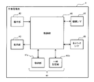
- FIG. 3 is a block diagram illustrating the configuration of the notification server 5 .
- the notification server 5 is configured by an information processing device such as a computer, for example.
- the notification server 5 illustrated in FIG. 3 includes a control unit 50 , a storage unit 51 , a device I/F 54 and a network I/F 55 .
- the control unit 50 includes, for example, a CPU or MPU that cooperates with software to realize predetermined functions.
- the control unit 50 controls the overall operation of the notification server 5, for example.
- the control unit 50 reads data and programs stored in the storage unit 51 and performs various arithmetic processing to realize various functions. Operations of various functions of the notification server 5 will be described later.
- the control unit 50 executes a program containing a group of instructions for realizing the functions of the notification server 5, for example.
- the above program may be provided from the communication network 3 or stored in a portable recording medium.
- the control unit 50 may include an internal memory as a temporary storage area for holding various data and programs.
- control unit 50 may be a hardware circuit such as a dedicated electronic circuit or a reconfigurable electronic circuit designed to realize each of the above functions.
- the control unit 50 may be composed of various semiconductor integrated circuits such as a CPU, MPU, GPU, GPGPU, TPU, microcomputer, DSP, FPGA, and ASIC.
- the storage unit 51 is a storage medium that stores programs and data necessary for realizing the functions of the notification server 5 .
- the storage unit 51 includes a storage unit 51a and a temporary storage unit 51b, as shown in FIG.
- the storage unit 51a stores parameters, data, control programs, etc. for realizing predetermined functions.
- the storage unit 51a is composed of, for example, an HDD or an SSD.
- the storage unit 51a stores the above program and map information indicating the arrangement of the facilities A1, A2, etc. in the workplace 6 in a predetermined coordinate system.
- the temporary storage unit 51b is composed of a RAM such as DRAM or SRAM, and temporarily stores data.
- the temporary storage unit 51b holds position information received from the worker terminal 4 and the like.
- the temporary storage unit 51 b may function as a work area of the control unit 50 or may be configured as a storage area in the internal memory of the control unit 50 .
- the device I/F 54 is a circuit for connecting external devices to the notification server 5 .
- the equipment I/F 54 performs communication according to a predetermined communication standard, for example, like the equipment I/F 44 of the operator terminal 4 .
- the device I/F 54 may constitute a communication unit that connects with an external device via the communication network 3 .
- the device I/F 54 may constitute an acquisition unit for receiving various information from an external device in the notification server 5 or an output unit for transmitting various information to the external device.
- the network I/F 55 is a circuit for connecting the notification server 5 to the communication network 3 via a wireless or wired communication line.
- Network I/F55 performs communication based on the predetermined
- Network I/F55 is an example of the communication part which performs worker terminal 4 and data communication in this embodiment.
- the network I/F 55 receives location information generated by the worker terminal 4 using beacon positioning technology, for example, through data communication with the worker terminal 4 .
- the network I/F 55 is an example of a location information acquisition section in this embodiment.
- the position information in the worker terminal 4 is not particularly limited to beacon positioning, and may be position information generated by positioning using a WiFi access point or positioning using GPS.
- the network I/F 55 establishes communication connections with the facilities A1 and A2 via the communication network 3, for example, and receives status information from the facilities A1 and A2 at any time.
- Network I/F 55 is an example of a state information acquisition unit in this embodiment.
- the network I/F 55 may constitute an acquisition unit that receives various information or an output unit that transmits various information in the notification server 5 via the communication network 3 .
- the configuration of the worker terminal 4 and the notification server 5 as described above is an example, and the configuration is not limited to the above example.
- the notification management method of this embodiment may be performed in distributed computing.
- various acquisition units in the operator terminal 4 and the notification server 5 may be realized by cooperation with various software in the control units 40 and 50, respectively.
- Each acquisition unit reads various information stored in various storage media (for example, storage units 41a and 51a) to work areas (for example, temporary storage units 41b and 51b) of control units 40 and 50, respectively, thereby obtaining various information. Acquisition may be performed.
- FIG. 1 An overview of the operation of the abnormality notification system 1 according to the present embodiment will be described with reference to FIGS. 1 and 4.
- FIG. 1 An overview of the operation of the abnormality notification system 1 according to the present embodiment will be described with reference to FIGS. 1 and 4.
- FIG. 1 An overview of the operation of the abnormality notification system 1 according to the present embodiment will be described with reference to FIGS. 1 and 4.
- FIG. 1 An overview of the operation of the abnormality notification system 1 according to the present embodiment will be described with reference to FIGS. 1 and 4.
- the notification server 5 receives status information from each of the facilities A1 and A2 via the communication network 3, for example. Detect abnormal conditions that occur.
- the notification server 5 transmits notification information to the worker terminals 4-1 to 4-3 of the workers W1 to W3.
- Each worker terminal 4 causes the display unit 43 to display the received notification information, for example.
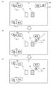
- FIG. 4 is a diagram for explaining the operation of the anomaly notification system 1 of this embodiment.
- FIG. 4 shows a view of the workplace 6 from above.
- FIG. 4(A) shows an example in which an abnormal state of specific equipment A2 is detected.
- the equipment A2 in the abnormal state is also referred to as the abnormal equipment A2.
- the notification server 5 sends notification information to the worker terminals 4-1 to 4-3 of all the workers W1 to W3 in the workplace 6 to call the detected abnormal facility A2. Send.
- all the workers W1 to W3 can be notified of the abnormal state of the equipment A2, and any worker W can quickly take action against the abnormal equipment A2.
- FIG. 4(B) shows an example of a worker W3 moving from the scene of FIG. 4(A) toward the abnormal facility A2 in response to a call based on the notification information received by the worker terminal 4-3. .
- the moved worker W3 will deal with the abnormal facility A2 and the abnormal state will be resolved.
- FIG. 4(B) shows an example of a worker W3 moving from the scene of FIG. 4(A) toward the abnormal facility A2 in response to a call based on the notification information received by the worker terminal 4-3.
- the worker terminals 4-1 and 4-2 corresponding to the other workers W1 and W2 are instructed to move to the abnormal facility A2. Send notification information to cancel the call.
- FIG. 4(C) shows an example in which the worker terminals 4-1 and 4-2 receive notification information to cancel the call after FIG. 4(B) and change the display.
- the workers W1 and W2 are notified of the cancellation, and only the worker W3 responds to the call to the abnormal facility A2.
- the worker W3 can be promptly secured as a person to deal with the abnormal facility A2, while the excessive labor of the other workers W1 and W2 can be reduced, thereby It is possible to efficiently deal with the equipment A2.
- FIG. 5 is a diagram for explaining an operation example of the system 1.
- FIG. 5 illustrates an operational sequence of the system 1 corresponding to the example of FIG.
- FIG. 6 is a diagram showing a display example of notification on the operator terminal 4 of the abnormality notification system 1. As shown in FIG.
- the notification server 5 acquires status information D21 and D22 indicating the operating status of each equipment A1 and A2 in the workplace 6 (S1).
- Each facility A1, A2 generates status information D21, D22, respectively, at predetermined time intervals, for example, and transmits it to the notification server 5 in association with the time.
- the status information D21 and D22 includes information indicating whether or not an abnormality such as a failure of each of the facilities A1 and A2 has occurred, and the content of the abnormality using an error code or the like.
- the notification server 5 of this embodiment detects an abnormal state of each facility A1, A2 based on, for example, the acquired state information D21, D22 (S2). In the example of FIG. 5, it is identified that the facility A2 is in an abnormal state based on the state information D22.
- the notification server 5 sends an abnormality notification D3 indicating that the facility A2 is in an abnormal state to each worker as notification information for calling each worker W to the detected abnormal facility A2, for example. It transmits to the terminal 4 (S3).
- an abnormality notification D3 is sent to worker terminals 4-1 to 4-3 corresponding to workers W1 to W3.
- each worker terminal 4 Upon receiving the abnormality notification D3 from the notification server 5, each worker terminal 4 causes the display unit 43 to display the abnormality notification D3 (S4).
- FIG. 6A shows a display example of the abnormality notification D3 on the worker terminal 4.
- FIG. The display unit 43 in FIG. 6A displays, for example, "NG” indicating that an abnormal state has been detected, and a message indicating details of the abnormality.
- a message indicating the occurrence of "failure E01" is displayed as the content of the abnormality in the abnormal facility A2.
- the notification server 5 After sending the abnormality notification D3 (S3), the notification server 5 detects the worker W moving to the abnormal equipment A2 (S5). Such movement detection processing (S5) is canceled when it is detected, among the plurality of workers W, that the operator has moved to the abnormal facility A2 in response to the display of the abnormality notification D3 (S4). This is done to send the notification D6 (S6).
- the notification server 5 for example, from worker terminals 4-1 to 4-3 corresponding to workers W1 to W3, respectively, each position transmitted at a predetermined cycle.
- the movement of the attendant is detected.
- the moving worker W3 is detected as the attendant based on the position information D43.
- the notification server 5 of the present embodiment sends a cancellation notification D6 indicating cancellation of the abnormality notification D3 as notification information for canceling the call to the abnormal facility A2, for example, to a person other than the responder. It is transmitted to the worker terminal 4 (S6).
- the notification server 5 transmits a cancellation notification D6 to the worker terminals 4-1 and 4-2 corresponding to the workers W1 and W2 other than the worker W3.
- each worker terminal 4 Upon receiving the cancellation notification D6 from the notification server 5, each worker terminal 4 causes the display unit 43 to display the cancellation notification D6 (S7).
- FIG. 6B shows a display example of the cancellation notice D6 on the operator terminal 4.
- FIG. The display unit 43 in FIG. 6B displays "OK" indicating that the abnormal state has been resolved, and a message indicating that the person responding to the notification in FIG. 6A has appeared. Note that the display control according to the cancellation notification D6 is not limited to the display example of FIG. 6B. may
- the anomaly notification system 1 repeats the above processes (S1 to S7), for example, periodically.
- the abnormal state of the equipment A2 detected in the abnormality detection process (S2) is notified to the worker W by the abnormality notification D3 (S3, S4). Thereafter, when the movement of the responder is detected by the movement detection process (S5), a cancellation notice D6 notifies the worker W other than the responder of the cancellation of the abnormality notice D3 (S6, S7).
- the abnormality notification D3 is canceled, for example, a plurality of workers W It is possible to suppress a decrease in work efficiency such as excessive concentration on the abnormal equipment A2.
- FIG. 1 Operation when Abnormality is Detected Operation of the notification server 5 when an abnormal state is detected in the abnormality notification system 1 as described above will be described with reference to FIGS. 7 to 9.
- FIG. 1 Operation when Abnormality is Detected Operation of the notification server 5 when an abnormal state is detected in the abnormality notification system 1 as described above will be described with reference to FIGS. 7 to 9.
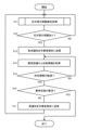
- FIG. 7 is a flowchart illustrating the operation of the anomaly notification system 1 of this embodiment when an anomaly is detected.
- FIG. 8 is a diagram for explaining movement detection processing in the anomaly notification system 1 of this embodiment.
- FIG. 9 is a diagram showing another display example on the worker terminal 4. As shown in FIG.
- the flowchart of FIG. 7 is started after sending (S3) of the abnormality notification D3, for example, in a state where the abnormal equipment A2 is identified in step S2 of FIG.
- Each process of this flowchart is executed by the control unit 50 of the notification server 5, for example.
- control unit 50 detects the moving worker W as the responder to the abnormality notification D3 (S11).
- the movement detection processing (S11) of the receptionist and the processing of step S12 correspond to step S5 in FIG. Note that this processing is also simply referred to as movement detection processing.
- the notification server 5 performs movement detection processing based on the position information received from each worker terminal 4 (S11). An example of generating position information on the worker terminal 4 side in the movement detection process of the present embodiment will be described with reference to FIG. 8 .
- the anomaly notification system 1 of this embodiment for example, as shown in FIG.
- the worker terminal 4 of the present embodiment communicates with the beacon transmitters 65 at various locations in the workplace 6 via the device I/F 44 to generate position information based on the information received from the nearby beacon transmitters 65. do. Details of the movement detection process (S11) will be described later.
- the control unit 50 determines whether the movement of the responder has been detected, that is, whether the worker W moving as the responder has been detected. It is determined whether or not (S12). When the control unit 50 determines that the movement of the respondent is not detected (NO in S12), the movement detection process (S11) is repeated at a predetermined detection cycle such as the transmission cycle of the position information by the worker terminal 4, for example.
- Step S13 corresponds to step S6 in FIG.
- the control unit 50 After sending the cancellation notice D6 (S13), the control unit 50 performs processing related to re-notification (S14-S17). Even if the abnormality notification system 1 detects the movement of the responder (YES in S12), the abnormal state may not be resolved, for example, because the responder does not reach the abnormal facility A2. Therefore, in the abnormality notification system 1 of the present embodiment, for example, when a predetermined period of time has passed without the abnormal state being resolved, processing is performed to re-notify each worker W of the abnormal state (S14 to S17).
- the control unit 50 acquires state information newly received from the abnormal equipment A2, for example, via the network I/F 55 (S14).
- the control unit 50 holds the acquired state information in, for example, the temporary storage unit 51b.
- the control unit 50 determines whether a predetermined period of time has elapsed since, for example, the transmission of the cancellation notice D6 (S13) (S15).
- the predetermined period is set, for example, from the viewpoint of estimating the period required until the detected attendant arrives at the abnormal facility A2 and the abnormal state is resolved by dealing with the abnormal facility A2. If the predetermined period has not elapsed (NO in S15), the control unit 50 repeats acquisition of state information from the abnormal equipment A2 (S14).
- the control unit 50 determines whether the abnormal state has been resolved based on the state information acquired from the abnormal equipment A2 (S16). For example, when the status information D22 does not indicate an abnormality in the facility A2 after some time within the predetermined period, the control unit 50 determines that the abnormal state has been resolved.
- FIG. 9 shows a display example of re-notification on the worker terminal 4.
- the display unit 43 illustrated in FIG. 9 displays, for example, a message such as "re-NG" indicating that the abnormal state notified by the abnormality notification D3 has not been resolved, and a message indicating that the attendant has not arrived at the abnormal facility A2. is displayed.
- control unit 50 After sending the re-notification (S17), the control unit 50 repeats the processes after the movement detection process (S11).
- control unit 50 ends the processing shown in this flowchart without executing re-notification transmission (S17).
- step S13 when sending the cancellation notice D6 (S13), an example was explained in which it is sent to some of the worker terminals 4 corresponding to the workers W other than the responders.
- the control unit 50 may transmit the cancellation notification D6 to all of the worker terminals 4 corresponding to each worker W including the responder.
- the determination of whether or not the abnormal state has been resolved (S16) is not limited to the state information at each time over the predetermined period, but may be made based on the state information at the last time of the predetermined period.
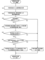
- FIG. 10 is a flowchart illustrating movement detection processing in the anomaly notification system 1 of this embodiment.
- the processing shown in this flow chart is started after the transmission of the abnormality notification D3 (S3) in a state where the abnormal facility A2 has been identified in step S2 of FIG. 5, for example, similarly to the flow chart of FIG.
- the control unit 50 acquires the position information D41 to D43 from the worker terminals 4-1 to 4-3, respectively, via the network I/F 55 as shown in FIG. 5 (S21).
- the position information D41 to D43 is, for example, among the plurality of beacon transmitters 65 installed in the workplace 6 as shown in FIG. is generated based on the position associated with the .
- control unit 50 calculates the current distances of the worker terminals 4-1 to 4-3 from the abnormal facility A2 based on the position information D41 to D43 acquired in step S21 this time (S22). .
- the control unit 50 calculates the current distance by calculating the Euclidean distance with reference to the map information including the position of the facility A2 in the workplace 6, which is stored in advance in the storage unit 51a, for example.
- control unit 50 determines whether or not the current distance between each worker terminal 4 and the abnormal equipment A2 calculated in step S21 in the previous movement detection process, that is, the previous distance is held (S23). . For example, the control unit 50 proceeds to NO in step S23 in the first movement detection process after the abnormal state is detected.
- control unit 50 stores the current distance calculated in step S11 as the previous distance in, for example, the temporary storage unit 51b (S27). After that, the process returns to step S12 in FIG. 7, and since the movement of the receptionist has not been detected (NO in S12), the movement detection process (S11) of the next detection cycle is executed.
- control unit 50 calculates the difference between the previous distance and the current distance, that is, the approach width for each worker terminal 4 (S24).
- the approach width of each worker terminal 4 is determined by the difference from the previous distance to the current distance to the abnormal facility A2. Shows the width of the distance approached toward
- control unit 50 determines whether or not there is a worker terminal 4 whose calculated approach width is greater than or equal to a predetermined value (S25).
- the predetermined value is set in advance as a value large enough to be regarded as having caused the worker W to move toward the abnormal facility A2 during the detection cycle in the workplace 6 .
- the control unit 50 determines the worker W corresponding to the worker terminal 4 as the attendant (S26).
- the width of approach calculated for the worker terminal 4-3 is greater than or equal to the predetermined value, and the worker W3 corresponding to the worker terminal 4-3 is determined as the attendant.
- the process proceeds to step S12 in FIG. In this case, since the movement of the respondent has been detected (YES in S12), a cancellation notice D6 is sent to workers W1 and W2 (S13).
- control unit 50 If there is no operator terminal 4 whose approach width is equal to or greater than the predetermined value (NO in S25), the control unit 50 retains the current distance as the previous distance (S27), and proceeds to step S12 in FIG. In this case, since the movement of the respondent has not been detected (NO in S12), the movement detection process (S11), that is, the processes after step S21 are executed again.
- the approach width is calculated for movement detection by the difference between the previous distance and the current distance to the abnormal equipment A2 for each worker terminal 4 (S24).
- the worker W corresponding to the worker terminal 4 is determined as the responder (S26).
- the worker W whose approach width is equal to or greater than a predetermined value.
- the position information D41 to D43 acquired in step S21 is not limited to the above examples.
- each of the worker terminals 4-1 to 4-3 estimates the distance to a plurality of beacon transmitters 65 based on the signal strength received from the beacon transmitter 65, and even if the calculated position information good.
- the beacon transmitter 65 is not limited to a device capable of communicating with the device I/F 44 of the worker terminal 4 according to the Bluetooth standard, and may be, for example, a WiFi access point.
- the notification server 5 in the present embodiment is an abnormality notification device that notifies the workers W1 to W3 as an example of a plurality of users of an abnormality in the facilities A1 and A2 installed in the workplace 6 as an example of the environment.
- the notification server 5 includes a network I/55 as an example of a communication section, a status information acquisition section, and a position information acquisition section, and a control section 50 .
- the network I/F 55 performs data communication with worker terminals 4-1 to 4-3 (an example of a plurality of terminal devices) respectively associated with a plurality of workers W1 to W3.
- the control unit 50 controls the operation of the network I/F 55 to transmit and receive information.
- the network I/F 55 acquires state information D21 and D22 indicating the states of the facilities A1 and A2 (S1).
- the network I/F 55 acquires position information D41-D43 indicating the positions of the workers W1-W3 in the workplace 6 (S5, S11, S21).
- the control unit 50 identifies that the facility A2 is in an abnormal state based on the state information D21 and D22 (S2), the plurality of worker terminals 4-1 to 4-3 are notified that the facility A2 is in an abnormal state. (S3).
- the control unit 50 After sending the abnormality notification D3, the control unit 50 selects the worker W3 as an example of a worker who moves to the abnormal facility A2, that is, the abnormal facility A2 among the plurality of workers W1 to W3 based on the position information D41 to D43. Detect (S5). When the moving worker W3 is detected, the control unit 50 sends a cancellation signal indicating cancellation of the abnormality notification D3 to some or all of the plurality of worker terminals 4-1 to 4-3 that have transmitted the abnormality notification D3. A notification D6 is sent (S6).
- the notification server 5 described above all of the workers W1 to W3 who responded to the abnormality notification D3 go to the abnormal facility A2 by the cancellation notification D6 while securing the worker W3 who will deal with the abnormal facility A2 by the abnormality notification D3. Excessive labor can be reduced. As a result, unnecessary movement of the worker W can be suppressed in coping with the abnormality of the facilities A1 and A2 in the workshop 6, and the coping with the abnormality can be efficiently performed.
- the control unit 50 selects one of the plurality of worker terminals 4-1 to 4-3 that have transmitted the abnormality notification D3.
- a cancellation notice D6 is transmitted to the worker terminals 4-1 and 4-2 associated with the workers W1 and W2 other than the worker W3 (S13).
- the control unit 50 determines whether or not the abnormal state has been resolved within a predetermined period of time after sending the cancellation notice D6 (S15).
- the control unit 50 determines that the abnormal state has not been resolved (NO in S16)
- it transmits a re-notification indicating cancellation of the cancellation notification D6 to the worker terminals 4-1 and 4-2 that transmitted the cancellation notification D6. (S17).
- the network I/F 55 (an example of the position information acquisition unit) sequentially receives the position information D41 to D43 from the worker terminals 4-1 to 4-3 respectively associated with the workers W1 to W3. (S21).
- the position information D41 to D43 is generated not only by positioning using the beacon transmitter 65, but also by positioning using, for example, a global positioning satellite system (GPS or GNSS). may be
- the control unit 50 calculates changes in the distance between each of the workers W1 to W3 and the abnormal facility A2 based on the position information D41 to D43 sequentially acquired from the network I/F 55. to detect the moving worker W (S22 to S27). As a result, it is possible to detect the movement of the respondent (S11), for example, based on the change in the distance between each worker W1 to W3 and the abnormal facility A2. In the present embodiment, the control unit 50 performs the work of moving the worker W3 whose approach width to the abnormal facility A2 at predetermined time intervals (for example, a predetermined period) is equal to or greater than a predetermined value as a change in the calculated distance. Person W is detected (S26).
- predetermined time intervals for example, a predetermined period
- the anomaly notification system 1 includes worker terminals 4-1 to 4-3 (examples of a plurality of terminal devices) respectively associated with a plurality of workers W1 to W3, a notification server 5 (an anomaly notification device is an example of a notification system including In such an anomaly notification system 1, the notification server 5 can efficiently deal with anomalies in the facilities A1 and A2 in the workplace 6.
- FIG. 1 An anomaly notification device is an example of a notification system including
- the abnormality notification method in this embodiment is a method of notifying workers W1 to W3 as an example of a plurality of users of an abnormality in the facilities A1 and A2 installed in the workplace 6 as an example of the environment.
- a notification server 5 acquires state information D21 and D22 indicating the states of the facilities A1 and A2 (S1).
- the network I/F 55 acquires position information D41-D43 indicating the positions of the workers W1-W3 in the workplace 6 (S5, S11, S21).
- the control unit 50 of the notification server 5 When the control unit 50 of the notification server 5 identifies that the facility A2 is in an abnormal state based on the state information D21 and D22 (S2), the plurality of worker terminals 4-1 to 4-3 are notified that the facility A2 is in an abnormal state. An abnormality notification D3 indicating the state is transmitted (S3). After transmitting the abnormality notification D3, the control unit 50 detects the worker W3 as an example of a worker who moves to the abnormal facility A2 among the plurality of workers W1 to W3 based on the position information D41 to D43 (S5).
- the control unit 50 sends a cancellation signal indicating cancellation of the abnormality notification D3 to some or all of the plurality of worker terminals 4-1 to 4-3 that have transmitted the abnormality notification D3.
- a notification D6 is sent (S6).
- a program for causing a computer to execute the abnormality notification method as described above. According to the abnormality notification method and program described above, it is possible to efficiently deal with the abnormality of the facilities A1 and A2 in the workshop 6. FIG.
- FIG. 2 Embodiment 2 of the present disclosure will be described below with reference to FIGS. 11 and 12.
- FIG. 1 the anomaly notification system 1 cancels the anomaly notification D3 when the movement of the worker W to the abnormal facility A2 is detected after the anomaly notification D3 is transmitted.
- an abnormality notification system 1 that controls cancellation of the abnormality notification D3 based on information on the worker W who moves to the abnormal facility A2 will be described.
- the notification server 5 determines whether or not each worker W is qualified to deal with the abnormal states of the facilities A1 and A2. Use the qualification information shown. For example, in the movement detection process, the notification server 5 of the present embodiment determines the worker W as the responder when the worker W whose movement to the abnormal facility A2 is detected does not correspond to the qualified worker in the qualified worker information. do not. As a result, when the worker W, who is assumed to be difficult to deal with the abnormal facility A2, goes to the abnormal facility A2, the abnormality notification D3 can be prevented from being cancelled.
- FIG. 11 is a diagram illustrating the data structure of the qualified person information D5 in the anomaly notification system 1 of this embodiment.
- the qualified person information D5 is stored in advance in the storage unit 51a of the notification server 5, for example.
- the qualified person information D5 is information for managing qualified persons regarding the abnormal states of the facilities A1 and A2.
- the qualified person in the qualified person information D5 is an example of a manager who manages the facilities A1 and A2 for the worker W in the workshop 6, and is set to a worker who is qualified to deal with abnormal conditions of the facilities A1 and A2. be.
- Qualified person information D5 is an example of administrator information indicating an administrator in this embodiment. In the example of FIG. 11, the qualified person information D5 is whether or not each worker W1, W2, W3 is qualified for each of the facilities A1, A2. to manage.
- FIG. 12 is a flowchart illustrating movement detection processing in the anomaly notification system 1 of this embodiment.
- the control unit 50 performs determination processing based on the qualified person information D5 (S31 ).
- the worker W corresponding to the worker terminal 4 is It is determined whether or not the person corresponds to the qualified person (S31).
- the determination in step S31 is based on, for example, the qualified person indicated by the qualified person information D5 stored in advance in the storage unit 51a and the worker W whose approach width is determined to be equal to or greater than a predetermined value in step S25, that is, the movement to the abnormal facility A2. is compared with the detected worker W.
- the control unit 50 assigns the worker W corresponding to the worker terminal 4 as a receptionist. (S26). For example, when the width of approach to the abnormal equipment A2 for the worker terminal 4-3 is equal to or greater than a predetermined value, the qualified worker information D5 shown in FIG. Therefore, it is determined by the respondent. After that, the controller 50 proceeds to step S12 in FIG.
- the control unit 50 does not determine the worker W as a receptionist. For example, when the width of approach for the worker terminal 4-2 is equal to or greater than a predetermined value, the worker W2 corresponding to the worker terminal 4-2 is not qualified for the facility A2 in the qualified worker information D5 of FIG. not determined by the person In this case (NO in S31), the control unit 50 holds the current distance as the previous distance (S27), as in the case where there is no worker terminal 4 whose approach width is equal to or greater than the predetermined value (NO in S25). The process proceeds to step S12 in FIG.
- the worker W corresponding to the qualified personnel for the abnormal facility A2 (YES in S31) is selected as the responder. determined (S26).
- the operator W can be selectively determined as the responder based on the qualified personnel information D5 regarding the abnormal facility A2.
- the cancellation notification D6 can be sent only when it is considered that the worker W who can deal with the abnormal facility A2 has responded to the abnormality notification D3 (S13 in FIG. 7).
- step S24 an example of calculating the width of approach to the abnormal facility A2 for all worker terminals 4 has been explained.
- the approach width calculation for detecting movement may be performed only for the worker terminal 4 of the qualified person.
- the control unit 50 acquires the position information only from the worker terminal 4 of the worker W corresponding to the qualified worker, and performs the processes after step S22 without particularly executing the process of step S31. you can go In this case as well, it is possible to determine the operator W who is qualified for the abnormal facility A2 and who moves to the abnormal facility A2.
- the cancellation notification D6 may include information indicating that the movement of the qualified person as the attendant has been detected.
- the display unit 43 may display that a qualified person has appeared.
- the notification server 5 in the present embodiment further includes a storage unit 51a (an example of a storage unit).
- Qualified person information D5 an example of administrator information
- a qualified person an example of an administrator to be managed
- the responder worker W3 an example of a moving user
- a cancellation notification D6 is transmitted (S13). If the responding worker W3 is not qualified for the abnormal facility A2 in the qualified worker information D5 (NO in S31), the control unit 50 does not send the cancellation notification D6.
- the notification server 5 described above if the responder who moves to the abnormal facility A2 is not qualified, the call to the abnormal facility A2 is continued by the abnormality notification D3. As a result, qualified workers W can be secured as responders, and abnormalities in the facilities A1 and A2 for a plurality of workers W can be dealt with efficiently.
- Embodiment 3 of the present disclosure will be described below with reference to FIGS. 13 and 14.
- FIG. 1 the anomaly notification system 1 that determines the responder using the qualified person information in the movement detection processing by the notification server 5 has been described.
- an abnormality notification system 1 capable of switching whether or not to display a notification on the worker terminal 4 will be described.
- FIG. 13 is a diagram showing a display example of the setting screen on the worker terminal 4 of this embodiment.
- each worker W uses his or her own worker terminal 4 to display notifications based on notification information such as abnormality notification D3, cancellation notification D6, and re-notification received from the notification server 5. or hide it.
- the display unit 43 of the worker terminal 4 displays the setting item "notification permission" set for all the facilities A1 and A2, and the "facility A1" and “facility A2" setting item and the terminal ID unique to each worker terminal 4 are displayed.
- the terminal ID "430" corresponding to the worker terminal 4-3 is displayed.
- the display unit 43 further displays "ON” and "OFF” for each setting item, that is, a selection button for switching between valid and invalid.
- the operation unit 42 of the worker terminal 4 inputs an operation by the worker W to select "ON" or "OFF".
- Validity or invalidity is set for the setting items of the facilities A1 and A2 by setting notification permission or by selecting "ON” or “OFF” of "facility A1” and “facility A2” respectively.
- the worker W3 can switch between display and non-display of notifications regarding the equipment A1 and A2.
- Each operator terminal 4 stores, for example, the storage unit 41a, setting information indicating display or non-display of the notification set on the setting screen.
- each worker terminal 4 transmits setting information to the notification server 5, for example, at predetermined intervals or when updated by user operation.
- the notification server 5 updates (or generates) the qualified person information D5 based on the setting information received from each worker terminal 4 .
- the notification server 5 updates the qualified person information D5 so that the worker W corresponding to the worker terminal 4 is a qualified person for the facility whose notification setting is "ON" in the setting information.
- the worker W3 corresponding to the worker terminal 4-3 whose terminal ID is "430" is qualified for the facility A2 whose notification setting is "ON", and sets the qualified worker information D5. can be updated.
- the worker terminal 4 of the present embodiment performs display control processing for controlling display when notification information is received from the notification server 5 based on the setting information.
- FIG. 14 is a flowchart illustrating display control processing in the worker terminal 4 of this embodiment. This flowchart is started, for example, in a state where the operator terminal 4 stores setting information. Each process shown in this flowchart is executed by the control unit 40 of the worker terminal 4, for example.
- control unit 40 determines whether notification information such as the abnormality notification D3 has been received from the notification server 5 via the network I/F 45, for example (S40). If notification information has not been received (NO in S40), control unit 40 repeats the determination in step S40.
- the control unit 40 refers to the setting information and determines whether or not the notification permission setting is "ON" (S41). An example in which the notification information regarding the facility A2 among the plurality of facilities A1 and A2 in the workshop 6 is received will be described below.
- the control unit 40 refers to the setting information regarding the facility A2 from which the notification information has been received, and determines whether the setting of the facility A2 is "ON”. (S42).
- the control unit 40 causes the display unit 43 to display a notification screen based on the notification information (S43).
- the notification information In the example of FIG. 13, in the worker terminal 4-3 with the terminal ID "430", the setting of notification permission is "ON” (YES in S41) and the setting of the facility A2 is "ON” (YES in S42). ). In this case, a notification screen regarding the equipment A2 is displayed on the display unit 43 of the worker terminal 4-3.
- the control unit 40 determines whether the notification permission setting is not "ON” (NO at S41), or if the setting for the facility A1 or facility A2 in the received notification information is not "ON” (NO at S42). If the notification permission setting is not “ON” (NO at S41), or if the setting for the facility A1 or facility A2 in the received notification information is not "ON” (NO at S42), the control unit 40 The notification information is not displayed on the display unit 43 (S44).
- control unit 40 After displaying the notification screen (S43) or not displaying the notification screen (S44), the control unit 40 terminates the processing shown in this flowchart.
- the worker terminal 4 controls whether or not to display the notification screen based on the received notification information based on the setting information (S40-S44).
- the setting information for example, notifications related to each worker W can be selectively displayed among the notifications about the facilities A1 and A2.
- each worker terminal 4 (an example of a terminal device) includes the network I/F 45 as an example of a terminal communication unit, the display unit 43, the operation unit 42, A control unit 40 is provided as an example of a terminal control unit.
- the network I/F 45 performs data communication with the notification server 5 (an example of an anomaly notification device).
- the display unit 43 displays information.
- the operation unit 42 receives user operations for setting setting information including display or non-display of notifications regarding the facilities A1 and A2.
- the control unit 40 switches whether to display the abnormality notification D3 and the cancellation notification D6 on the display unit 43 based on the setting information (S40 to S44).
- each worker W who is an example of a user, can display notification information such as an abnormality notification D3 and a cancellation notification D6 for equipment related to himself/herself among the equipment A1 and A2.
- notification information such as an abnormality notification D3 and a cancellation notification D6 for equipment related to himself/herself among the equipment A1 and A2.
- the qualified person information D5 which is an example of administrator information
- setting information which is an example of information received by the network I/F 55 (an example of the communication unit) from a plurality of worker terminals 4.
- the worker W an example of a user
- the control unit 50 updates the qualified person information D5 with the worker W associated with the worker terminal 4 that has transmitted the predetermined information as the qualified person.
- the qualified persons in the qualified person information D5 can be efficiently managed by using the setting information set by each worker W according to whether or not the abnormal state can be dealt with for each of the facilities A1 and A2.
- Embodiment 4 of the present disclosure will be described below with reference to FIGS. 15 and 16.
- FIG. 1 the anomaly notification system 1 that acquires position information transmitted from the worker terminal 4 and detects movement of the worker W has been described.
- an abnormality notification system 1A that detects movement of the worker W by image recognition in the workplace 6 will be described.
- An abnormality notification system 1A according to this embodiment will be described below, omitting the description of the same configuration and operation as those of the abnormality notification system 1 according to Embodiments 1 to 3.
- FIG. 15 is a diagram for explaining the anomaly notification system 1A according to this embodiment.
- This system 1A includes a plurality of cameras 2-1, 2-2, and 2-3 in addition to the same configuration as the abnormality notification system 1 of the first embodiment.
- the cameras 2-1 to 2-3 are also collectively referred to as cameras 2 below. Although three cameras 2-1 to 2-3 are illustrated in FIG. 15, the number of cameras 2 included in the system 1A is not particularly limited to three, and may be two or less or four or more. good too.
- the camera 2 is an example of an imaging device in this system 1A.
- the camera 2 includes an imaging unit that captures an image, and a communication unit that transmits image data representing the captured image captured by the imaging unit.
- the imaging unit is realized by a CCD image sensor, a CMOS image sensor, or the like.
- the communication unit includes an interface circuit for communicating with an external device in compliance with a predetermined communication standard such as IEEE802.11.
- the cameras 2-1 and 2-2 are arranged so as to capture the facilities A1 and A2, respectively.
- the camera 2-3 is placed at a distance from the facilities A1 and A2 in the workplace 6 so as to capture the range in which the worker W moves.
- the camera 2 repeats the imaging operation at predetermined intervals, for example, in the workplace 6, and generates image data representing the captured image.
- the camera 2 is connected to a notification server 5 such that for example image data is sent to the notification server 5 .
- the notification server 5 uses an image recognition technique to recognize the position of the worker W in an image captured by the camera 2-3, for example, thereby performing the process of detecting the movement of the respondent. . Further, after transmitting the cancellation notice D6, the notification server 5 performs image recognition processing for detecting a predetermined gesture of the respondent, for example, in the image captured by the camera 2-2 showing the abnormal facility A2.
- the predetermined gesture is a gesture in which a person such as the worker W, who is the responder, crosses his/her arms in order to request transmission of the re-notification.
- FIG. 16 is a flowchart illustrating the operation of the anomaly notification system 1A of this embodiment when an anomaly is detected.
- the control unit 50 performs movement detection processing (S11A) by image recognition instead of the movement detection processing (S11 in FIG. 7) using the position information from the worker terminal 4 in the first to third embodiments. I do.
- the control unit 50 performs processing (S51, S52) regarding re-notification in response to a predetermined gesture by the worker W, in addition to the processing similar to that of step S11A and steps S12 to S17 of FIG. Execute.
- the control unit 50 acquires image data from the camera 2-1 via the network I/F 55, and performs the movement detection processing (S11A) of the respondent by image recognition.
- the control unit 50 recognizes the positions of the workers W1 to W3 by image recognition based on the obtained image data, and generates position information indicating the positions of the workers W1 to W3 in the workplace 6.
- FIG. The control unit 50 is an example of a position information acquisition unit in this embodiment. Image recognition processing for recognizing such a position is realized, for example, by using a learned model by various machine learning or by various image recognition algorithms. Based on the generated position information D41-D43, the control unit 50 performs the same processing as steps S22-S27 in FIG. 10, for example.
- the control unit 50 transmits a cancellation notice D6 (S13) and acquires status information from, for example, the abnormal equipment A2 (S14). Furthermore, the control unit 50 of the present embodiment acquires image data from the camera 2-2 that shows the abnormal facility A2, for example, via the network I/F 55, and based on the image data, performs a predetermined gesture of the respondent. Image recognition processing for detection is performed (S51).
- the image recognition processing in step S51 is realized by using, for example, an image of a person performing a predetermined gesture as training data, and using a model that has been learned by various types of machine learning.
- the control unit 50 inputs the image of the area near the abnormal facility A2 in the acquired image data to the learned model, and acquires the recognition result of the gesture from the learned model. Based on the acquired recognition result (S51), the control unit 50 determines whether or not the predetermined gesture of the attendant has been detected (S52).
- the control unit 50 sends a re-notification to the worker terminal 4 corresponding to the worker W other than the responder, for example (S17).
- the control unit 50 may include, for example, the captured image in which the predetermined gesture is detected in the re-notification and transmit it.
- the worker W who has received the re-notification on the worker terminal 4 can confirm the responder by displaying the captured image.
- control unit 50 proceeds to step S15.
- the movement detection processing of the respondent is performed by image recognition based on the image data from the camera 2-3 (S11A).
- the movement detection process can be performed using the camera 2-3 that captures images of the worker W moving in the workplace 6.
- the predetermined gesture by the respondent is detected by the image recognition (S51) of the predetermined gesture based on the image data from the camera 2-2 that captures the abnormal facility A2 (YES in S52)
- re-notification is performed. It is transmitted (S17).
- another worker W can be called by re-notification.
- the worker terminal 4 does not need to generate position information and transmit it to the notification server 5. Further, when detecting an abnormal state of the facilities A1 and A2 (S2 in FIG. 5), for example, the lamps installed in each of the facilities A1 and A2 indicating the operating status can be photographed by the cameras 2-1 and 2-2. Therefore, the operating states of the facilities A1 and A2 may be determined from the captured images without using the state information. Further, in the anomaly notification system 1A, the cameras that capture the images of the facilities A1 and A2 are not limited to the cameras 2-1 and 2-2. It may be implemented by a camera that captures the workplace 6 .
- a camera installed so as to capture the entire range in which the worker W moves in the workplace 6 is used to detect movement by image recognition (S11A) and a predetermined Gesture image recognition (S51) may be performed.
- the network I/F 55 which is an example of a communication unit, receives image data (first example of image data).
- the control unit 50 which is an example of the positional information acquisition unit, detects each worker W (an example of a user) in the captured image indicated by the image data received from the camera 2-3. A position is recognized and position information is acquired (S11A). Thereby, even if each worker terminal 4 does not generate the position information D41 to D43 and transmit it to the notification server 5, the notification server 5 can perform movement detection processing using the position information based on the image data.
- the network I/F 55 receives image data (second image example of data).
- the control unit 50 responds to the worker W (an example of a user ) is detected (S51).
- the control unit 50 transmits a re-notification indicating cancellation of the cancellation notification D6 (S17).
- the responder performs a predetermined gesture to prompt the transmission of the re-notification, and the abnormal state is detected. It is possible to secure another worker W to deal with.
- Embodiments 1 to 4 have been described as examples of the technology disclosed in the present application.
- the technology in the present disclosure is not limited to this, and can also be applied to embodiments in which modifications, substitutions, additions, omissions, etc. are made as appropriate.
- notification information such as the abnormal notification D3 is sent to the worker terminals 4 of all the workers W in the workplace 6.
- the sending notification server 5 has been described.
- the notification server 5 may transmit notification information only to some worker terminals 4 .
- the notification server 5 may transmit notification information to the worker terminal 4 of the worker W located in a specific area in the workplace 6 based on the worker W's location information.
- it is possible to perform selective notification such as not notifying the worker W in the conference room, or notifying only the worker W who is within a predetermined range from the abnormal equipment. It is possible to make it easier to suppress a decrease in work efficiency.
- the notification server 5 transmits the cancellation notification D6 to the worker terminal 4 (S13) regardless of the number of attendants when the movement of the attendant is detected (YES in S12).
- the notification server 5 may transmit (S13) the cancellation notification D6 according to the number of attendants.
- the control unit 50 proceeds to step S13 only when movement of a predetermined number (for example, two) or more of receptionists is detected, and when the number of receptionists is less than the predetermined number, repeats the movement detection process. good too.
- the anomaly notification system may include a camera installed so as to capture the worker W, like the camera 2-3 in the anomaly notification system 1A of the fourth embodiment.
- the anomaly notification system recognizes features such as the color of the worker W's clothes such as a hat or the presence or absence of an armband based on the image data from the camera. It may be determined whether or not the person W is qualified.
- the control unit 50 of the notification server 5 in this system may acquire image data from the camera and apply image recognition processing for recognizing the above characteristics.
- the notification server 5 performs the processing related to re-notification (S14 to S17) after transmitting the cancellation notification D6.
- the notification server 5 does not have to execute the processing (S14 to S17) relating to re-notification.
- the site to which the anomaly notification system 1, 1A and the notification server 5 are applied is not limited to the workshop 6, but may be various sites such as distribution warehouses or store sales floors.
- the present disclosure is applicable to various notification systems that notify information that induces movement to multiple workers in various environments such as factories, distribution sites, and stores.
Abstract
Description
1.構成
実施形態1に係る異常通知システムについて、図1を用いて説明する。図1は、本実施形態に係る異常通知システム1の概要を示す図である。
本実施形態の異常通知システム1は、例えば図1に示すように、作業者端末4-1,4-2,4-3と、通知サーバ5とを備える。本システム1において、作業者端末4と通知サーバ5とは、例えばインターネット等の通信ネットワーク3を介して通信可能に構成される。
図2は、作業者端末4の構成を例示するブロック図である。作業者端末4は、例えばスマートフォン或いはタブレット端末のような情報処理装置で構成される。図2に例示する作業者端末4は、制御部40と、記憶部41と、操作部42と、表示部43と、機器インタフェース44と、ネットワークインタフェース45とを備える。以下、インタフェースを「I/F」と略記する。
図3は、通知サーバ5の構成を例示するブロック図である。通知サーバ5は、例えばコンピュータのような情報処理装置で構成される。図3に例示する通知サーバ5は、制御部50と、記憶部51と、機器I/F54と、ネットワークI/F55とを備える。
以上のように構成される異常通知システム1、通知サーバ5及び作業者端末4の動作について、以下説明する。
本実施形態における異常通知システム1の動作の概要について、図1及び図4を用いて説明する。
本実施形態における異常通知システム1の全体的な動作を、図5及び図6を用いて説明する。図5は、本システム1の動作例を説明するための図である。図5は、図4の例に対応した本システム1の動作シーケンスを例示する。図6は、異常通知システム1の作業者端末4における通知の表示例を示す図である。
以上のような異常通知システム1において、異常状態が検知された際の通知サーバ5の動作を、図7~図9を用いて説明する。
図7のステップS11における移動検知処理の詳細を、図5及び図10を用いて説明する。
以上のように、本実施形態における通知サーバ5は、環境の一例として作業場6に設置された設備A1,A2の異常を、複数のユーザの一例として作業者W1~W3に通知する異常通知装置の一例である。通知サーバ5は、通信部、状態情報取得部、および位置情報取得部の一例としてネットワークI/55と、制御部50とを備える。ネットワークI/F55は、複数の作業者W1~W3にそれぞれ関連付けられた作業者端末4-1~4-3(複数の端末装置の一例)とデータ通信を行う。制御部50は、ネットワークI/F55の動作を制御して情報を送受信する。ネットワークI/F55は、設備A1,A2の状態を示す状態情報D21,D22を取得する(S1)。ネットワークI/F55は、作業場6における各作業者W1~W3の位置を示す位置情報D41~D43を取得する(S5,S11,S21)。制御部50は、状態情報D21,D22に基づいて設備A2が異常状態であることを特定すると(S2)、複数の作業者端末4-1~4-3に、設備A2が異常状態であることを示す異常通知D3を送信する(S3)。制御部50は、異常通知D3の送信後に、位置情報D41~D43に基づいて複数の作業者W1~W3において異常状態の設備A2、すなわち異常設備A2に移動する作業者の一例として作業者W3を検知する(S5)。制御部50は、移動する作業者W3を検知したとき、異常通知D3を送信した複数の作業者端末4-1~4-3のうちの一部又は全体に、異常通知D3の取り消しを示す取消通知D6を送信する(S6)。
以下、図11及び図12を用いて、本開示の実施形態2を説明する。実施形態1では、異常通知D3の送信後に異常設備A2への作業者Wの移動を検知すると、異常通知D3を取り消す異常通知システム1を説明した。実施形態2では、異常設備A2に移動する作業者Wの情報に基づいて、異常通知D3の取り消しを制御する異常通知システム1を説明する。
以下、図13及び図14を用いて、本開示の実施形態3を説明する。実施形態2では、通知サーバ5による移動検知処理において、資格者情報を用いて応対者を決定する異常通知システム1を説明した。実施形態3では、さらに作業者端末4において通知を表示させるか否かを切り替え可能な異常通知システム1を説明する。
以下、図15及び図16を用いて本開示の実施形態4を説明する。実施形態1~3では、作業者端末4から送信される位置情報を取得して、作業者Wの移動を検知する異常通知システム1を説明した。実施形態4では、作業場6における画像認識によって作業者Wの移動を検知する異常通知システム1Aを説明する。
以上のように、本出願において開示する技術の例示として、実施形態1~4を説明した。しかしながら、本開示における技術は、これに限定されず、適宜、変更、置換、付加、省略などを行った実施の形態にも適用可能である。また、上記各実施形態で説明した各構成要素を組み合わせて、新たな実施の形態とすることも可能である。そこで、以下、他の実施形態を例示する。
Claims (13)
- 環境に設置された設備の異常を、複数のユーザに通知する異常通知装置であって、
前記複数のユーザにそれぞれ関連付けられた複数の端末装置とデータ通信を行う通信部と、
前記通信部の動作を制御して情報を送受信する制御部と、
前記設備の状態を示す状態情報を取得する状態情報取得部と、
前記環境における各ユーザの位置を示す位置情報を取得する位置情報取得部とを備え、
前記制御部は、
前記状態情報に基づいて前記設備が異常状態であることを特定すると、前記複数の端末装置に、前記設備が前記異常状態であることを示す異常通知を送信し、
前記異常通知の送信後に、前記位置情報に基づいて前記複数のユーザにおいて前記異常状態の設備に移動するユーザを検知し、
前記移動するユーザを検知したとき、前記異常通知を送信した複数の端末装置のうちの一部又は全体に、前記異常通知の取り消しを示す取消通知を送信する
異常通知装置。 - 前記制御部は、前記移動するユーザを検知したとき、前記異常通知を送信した複数の端末装置のうちの、前記検知されたユーザ以外のユーザと関連付けられた端末装置に、前記取消通知を送信する
請求項1に記載の異常通知装置。 - 前記制御部は、
前記取消通知を送信してから所定期間中に、前記異常状態が解消されたか否かを判断し、
前記異常状態が解消されていないと判断すると、前記取消通知を送信した端末装置に、前記取消通知の取り消しを示す再通知を送信する
請求項1又は2に記載の異常通知装置。 - 前記制御部は、前記位置情報取得部から順次、取得される位置情報に基づいて、前記各ユーザと前記異常状態の設備との間の距離の変化を算出して、前記移動するユーザを検知する
請求項1から3のいずれか1項に記載の異常通知装置。 - 前記複数のユーザにおいて前記設備を管理する管理者を示す管理者情報を格納する記憶部をさらに備え、
前記制御部は、
前記移動するユーザが、前記管理者情報において、前記異常状態の設備に関して前記管理者である場合、前記取消通知を送信し、
前記移動するユーザが、前記管理者情報において、前記異常状態の設備に関して前記管理者でない場合、前記取消通知を送信しない
請求項1から4のいずれか1項に記載の異常通知装置。 - 前記管理者情報は、前記通信部が前記複数の端末装置から受信した情報に基づいて、前記通信部に所定の情報を送信した端末装置に関連付けられたユーザを前記管理者として管理する
請求項5に記載の異常通知装置。 - 前記位置情報取得部は、前記各ユーザにそれぞれ関連付けられた前記各端末装置から順次、前記位置情報を取得する
請求項1から6のいずれか1項に記載の異常通知装置。 - 前記通信部は、前記環境を撮像する第1の撮像装置から第1の画像データを受信し、
前記位置情報取得部は、前記第1の撮像装置から受信された第1の画像データに基づいて、前記第1の画像データが示す撮像画像において各ユーザの位置を認識して、前記位置情報を取得する
請求項1から6のいずれか1項に記載の異常通知装置。 - 前記通信部は、前記異常状態の設備を撮像する第2の撮像装置から第2の画像データを受信し、
前記制御部は、
前記取消通知の送信後に、前記第2の撮像装置から受信された第2の画像データに基づいて、前記第2の画像データが示す撮像画像に含まれるユーザのジェスチャーを検知し、
所定のジェスチャーを検知すると、前記取消通知の取り消しを示す再通知を送信する
請求項1から8のいずれか1項に記載の異常通知装置。 - 前記複数のユーザにそれぞれ関連付けられた複数の端末装置と、
請求項1から9のいずれか1項に記載の異常通知装置と、を備えた
通知システム。 - 前記各端末装置は、
前記異常通知装置とデータ通信する端末通信部と、
情報を表示する表示部と、
前記設備に関する通知の表示または非表示を含む設定情報を設定するユーザ操作を受け付ける操作部と、
前記設定情報に基づいて、前記異常通知及び前記取消通知を前記表示部に表示させるか否かを切り替える端末制御部とを備える
請求項10に記載の通知システム。 - 環境に設置された設備の異常を、複数のユーザに通知する異常通知方法であって、
前記複数のユーザにそれぞれ関連付けられた複数の端末装置とデータ通信を行うコンピュータの通信部が、
前記設備の状態を示す状態情報を取得し、
前記環境における各ユーザの位置を示す位置情報を取得し、
前記コンピュータの制御部が、
前記状態情報に基づいて前記設備が異常状態であることを特定すると、前記複数の端末装置に、前記設備が前記異常状態であることを示す異常通知を送信し、
前記異常通知の送信後に、前記位置情報に基づいて前記複数のユーザにおいて前記異常状態の設備に移動するユーザを検知し、
前記移動するユーザを検知したとき、前記異常通知を送信した複数の端末装置のうちの一部又は全体に、前記異常通知の取り消しを示す取消通知を送信する
異常通知方法。 - 請求項12に記載の異常通知方法をコンピュータの制御部に実行させるためのプログラム。
Priority Applications (2)
| Application Number | Priority Date | Filing Date | Title |
|---|---|---|---|
| CN202280052202.3A CN117730526A (zh) | 2021-07-29 | 2022-05-26 | 异常通知装置、方法以及系统 |
| JP2023538303A JPWO2023007934A1 (ja) | 2021-07-29 | 2022-05-26 |
Applications Claiming Priority (2)
| Application Number | Priority Date | Filing Date | Title |
|---|---|---|---|
| JP2021124660 | 2021-07-29 | ||
| JP2021-124660 | 2021-07-29 |
Publications (1)
| Publication Number | Publication Date |
|---|---|
| WO2023007934A1 true WO2023007934A1 (ja) | 2023-02-02 |
Family
ID=85086602
Family Applications (1)
| Application Number | Title | Priority Date | Filing Date |
|---|---|---|---|
| PCT/JP2022/021529 WO2023007934A1 (ja) | 2021-07-29 | 2022-05-26 | 異常通知装置、方法、及びシステム |
Country Status (3)
| Country | Link |
|---|---|
| JP (1) | JPWO2023007934A1 (ja) |
| CN (1) | CN117730526A (ja) |
| WO (1) | WO2023007934A1 (ja) |
Citations (7)
| Publication number | Priority date | Publication date | Assignee | Title |
|---|---|---|---|---|
| JP2009005026A (ja) * | 2007-06-20 | 2009-01-08 | Sharp Corp | 電話機およびその制御方法、電話機システム、電話機制御プログラム、並びに、該プログラムを記録した記録媒体 |
| JP2009022590A (ja) * | 2007-07-20 | 2009-02-05 | Hitachi Ltd | ナースコールシステムおよび患者異常対応方法 |
| JP2010182269A (ja) * | 2009-02-09 | 2010-08-19 | Ishida Co Ltd | レジシステム |
| JP2014123165A (ja) * | 2012-12-20 | 2014-07-03 | Konica Minolta Inc | エラー通知装置、画像形成装置 |
| JP2016087804A (ja) * | 2014-10-30 | 2016-05-23 | 京セラドキュメントソリューションズ株式会社 | 画像形成装置 |
| JP2017156882A (ja) | 2016-02-29 | 2017-09-07 | 東芝テック株式会社 | 作業割当支援装置、端末装置及びプログラム |
| JP2018067098A (ja) * | 2016-10-18 | 2018-04-26 | 株式会社東芝 | 通知システム、情報取得装置、端末装置及び通知方法 |
-
2022
- 2022-05-26 CN CN202280052202.3A patent/CN117730526A/zh active Pending
- 2022-05-26 WO PCT/JP2022/021529 patent/WO2023007934A1/ja active Application Filing
- 2022-05-26 JP JP2023538303A patent/JPWO2023007934A1/ja active Pending
Patent Citations (7)
| Publication number | Priority date | Publication date | Assignee | Title |
|---|---|---|---|---|
| JP2009005026A (ja) * | 2007-06-20 | 2009-01-08 | Sharp Corp | 電話機およびその制御方法、電話機システム、電話機制御プログラム、並びに、該プログラムを記録した記録媒体 |
| JP2009022590A (ja) * | 2007-07-20 | 2009-02-05 | Hitachi Ltd | ナースコールシステムおよび患者異常対応方法 |
| JP2010182269A (ja) * | 2009-02-09 | 2010-08-19 | Ishida Co Ltd | レジシステム |
| JP2014123165A (ja) * | 2012-12-20 | 2014-07-03 | Konica Minolta Inc | エラー通知装置、画像形成装置 |
| JP2016087804A (ja) * | 2014-10-30 | 2016-05-23 | 京セラドキュメントソリューションズ株式会社 | 画像形成装置 |
| JP2017156882A (ja) | 2016-02-29 | 2017-09-07 | 東芝テック株式会社 | 作業割当支援装置、端末装置及びプログラム |
| JP2018067098A (ja) * | 2016-10-18 | 2018-04-26 | 株式会社東芝 | 通知システム、情報取得装置、端末装置及び通知方法 |
Also Published As
| Publication number | Publication date |
|---|---|
| CN117730526A (zh) | 2024-03-19 |
| JPWO2023007934A1 (ja) | 2023-02-02 |
Similar Documents
| Publication | Publication Date | Title |
|---|---|---|
| JP5995243B2 (ja) | 見守りシステム | |
| WO2007043557A1 (ja) | エレベータの遠隔監視システム、エレベータの遠隔監視方法及びコードシール | |
| JP6230567B2 (ja) | 設備機器監視システム | |
| JP6552755B1 (ja) | エレベーターの制御装置および制御方法 | |
| US20180177395A1 (en) | Central processing device and central processing method for system for monitoring persons to be monitored, and system for monitoring persons to be monitored | |
| WO2023007934A1 (ja) | 異常通知装置、方法、及びシステム | |
| JP2003067877A (ja) | 保守監視システム、保守監視方法及び保守監視用プログラム | |
| JP5010560B2 (ja) | 監視制御システム及び監視装置 | |
| JP2014139745A (ja) | 機器管理システム、機器管理装置、機器管理方法及びプログラム | |
| JP2019079419A (ja) | ロボット管理システム | |
| JP2020166873A (ja) | システム、システムの制御方法、制御プログラム、制御プログラムを記録したコンピューター読み取り可能な記録媒体、および情報管理者端末 | |
| JP2010006514A (ja) | 現地エレベータの物件データ確認システム | |
| JP2005157529A (ja) | 受付システム、受付サーバ装置及びプログラム | |
| JP2021157218A (ja) | 工場監視システム | |
| JP2005153104A (ja) | コンピュータメンテナンスロボットシステム及びコールによる保守作業方法及び巡回点検方法及びそのプログラム | |
| JP5518956B2 (ja) | 作業管理装置、作業管理方法およびプログラム | |
| JP6654852B2 (ja) | 警備業務支援システム及び遠隔装置 | |
| JP6386763B2 (ja) | 支援システム | |
| JP2007112541A (ja) | 保守員の動静管理システム | |
| JP7019641B2 (ja) | メータ管理システム及びメータ管理携帯端末 | |
| US11388544B2 (en) | Portable computing device assisted mustering | |
| JP6669463B2 (ja) | 警備業務支援システム、遠隔装置、携帯端末装置及びプログラム | |
| JP6744184B2 (ja) | 発電システム、発電システムの運用方法、端末装置及び端末装置の制御方法 | |
| JP2003288400A (ja) | ビル群管理システム | |
| WO2019216058A1 (ja) | システムおよびシステムの制御方法 |
Legal Events
| Date | Code | Title | Description |
|---|---|---|---|
| 121 | Ep: the epo has been informed by wipo that ep was designated in this application |
Ref document number: 22849013 Country of ref document: EP Kind code of ref document: A1 |
|
| WWE | Wipo information: entry into national phase |
Ref document number: 2023538303 Country of ref document: JP |
|
| WWE | Wipo information: entry into national phase |
Ref document number: 2022849013 Country of ref document: EP |
|
| NENP | Non-entry into the national phase |
Ref country code: DE |
|
| ENP | Entry into the national phase |
Ref document number: 2022849013 Country of ref document: EP Effective date: 20240229 |