WO2022224610A1 - 空気入りタイヤ - Google Patents
空気入りタイヤ Download PDFInfo
- Publication number
- WO2022224610A1 WO2022224610A1 PCT/JP2022/010235 JP2022010235W WO2022224610A1 WO 2022224610 A1 WO2022224610 A1 WO 2022224610A1 JP 2022010235 W JP2022010235 W JP 2022010235W WO 2022224610 A1 WO2022224610 A1 WO 2022224610A1
- Authority
- WO
- WIPO (PCT)
- Prior art keywords
- band
- pneumatic tire
- tex
- less
- tire
- Prior art date
- Legal status (The legal status is an assumption and is not a legal conclusion. Google has not performed a legal analysis and makes no representation as to the accuracy of the status listed.)
- Ceased
Links
Images


Classifications
-
- B—PERFORMING OPERATIONS; TRANSPORTING
- B60—VEHICLES IN GENERAL
- B60C—VEHICLE TYRES; TYRE INFLATION; TYRE CHANGING; CONNECTING VALVES TO INFLATABLE ELASTIC BODIES IN GENERAL; DEVICES OR ARRANGEMENTS RELATED TO TYRES
- B60C9/00—Reinforcements or ply arrangement of pneumatic tyres
- B60C9/005—Reinforcements made of different materials, e.g. hybrid or composite cords
-
- B—PERFORMING OPERATIONS; TRANSPORTING
- B60—VEHICLES IN GENERAL
- B60C—VEHICLE TYRES; TYRE INFLATION; TYRE CHANGING; CONNECTING VALVES TO INFLATABLE ELASTIC BODIES IN GENERAL; DEVICES OR ARRANGEMENTS RELATED TO TYRES
- B60C11/00—Tyre tread bands; Tread patterns; Anti-skid inserts
- B60C11/03—Tread patterns
- B60C11/0327—Tread patterns characterised by special properties of the tread pattern
- B60C11/033—Tread patterns characterised by special properties of the tread pattern by the void or net-to-gross ratios of the patterns
-
- B—PERFORMING OPERATIONS; TRANSPORTING
- B60—VEHICLES IN GENERAL
- B60C—VEHICLE TYRES; TYRE INFLATION; TYRE CHANGING; CONNECTING VALVES TO INFLATABLE ELASTIC BODIES IN GENERAL; DEVICES OR ARRANGEMENTS RELATED TO TYRES
- B60C9/00—Reinforcements or ply arrangement of pneumatic tyres
- B60C9/0042—Reinforcements made of synthetic materials
-
- B—PERFORMING OPERATIONS; TRANSPORTING
- B60—VEHICLES IN GENERAL
- B60C—VEHICLE TYRES; TYRE INFLATION; TYRE CHANGING; CONNECTING VALVES TO INFLATABLE ELASTIC BODIES IN GENERAL; DEVICES OR ARRANGEMENTS RELATED TO TYRES
- B60C9/00—Reinforcements or ply arrangement of pneumatic tyres
- B60C9/18—Structure or arrangement of belts or breakers, crown-reinforcing or cushioning layers
- B60C9/20—Structure or arrangement of belts or breakers, crown-reinforcing or cushioning layers built-up from rubberised plies each having all cords arranged substantially parallel
- B60C9/2003—Structure or arrangement of belts or breakers, crown-reinforcing or cushioning layers built-up from rubberised plies each having all cords arranged substantially parallel characterised by the materials of the belt cords
- B60C9/2009—Structure or arrangement of belts or breakers, crown-reinforcing or cushioning layers built-up from rubberised plies each having all cords arranged substantially parallel characterised by the materials of the belt cords comprising plies of different materials
-
- B—PERFORMING OPERATIONS; TRANSPORTING
- B60—VEHICLES IN GENERAL
- B60C—VEHICLE TYRES; TYRE INFLATION; TYRE CHANGING; CONNECTING VALVES TO INFLATABLE ELASTIC BODIES IN GENERAL; DEVICES OR ARRANGEMENTS RELATED TO TYRES
- B60C9/00—Reinforcements or ply arrangement of pneumatic tyres
- B60C9/18—Structure or arrangement of belts or breakers, crown-reinforcing or cushioning layers
- B60C9/20—Structure or arrangement of belts or breakers, crown-reinforcing or cushioning layers built-up from rubberised plies each having all cords arranged substantially parallel
- B60C2009/2061—Physical properties or dimensions of the belt coating rubber
- B60C2009/2064—Modulus; Hardness; Loss modulus or "tangens delta"
-
- B—PERFORMING OPERATIONS; TRANSPORTING
- B60—VEHICLES IN GENERAL
- B60C—VEHICLE TYRES; TYRE INFLATION; TYRE CHANGING; CONNECTING VALVES TO INFLATABLE ELASTIC BODIES IN GENERAL; DEVICES OR ARRANGEMENTS RELATED TO TYRES
- B60C9/00—Reinforcements or ply arrangement of pneumatic tyres
- B60C9/18—Structure or arrangement of belts or breakers, crown-reinforcing or cushioning layers
- B60C9/20—Structure or arrangement of belts or breakers, crown-reinforcing or cushioning layers built-up from rubberised plies each having all cords arranged substantially parallel
- B60C2009/2061—Physical properties or dimensions of the belt coating rubber
- B60C2009/2067—Thickness
-
- B—PERFORMING OPERATIONS; TRANSPORTING
- B60—VEHICLES IN GENERAL
- B60C—VEHICLE TYRES; TYRE INFLATION; TYRE CHANGING; CONNECTING VALVES TO INFLATABLE ELASTIC BODIES IN GENERAL; DEVICES OR ARRANGEMENTS RELATED TO TYRES
- B60C9/00—Reinforcements or ply arrangement of pneumatic tyres
- B60C9/18—Structure or arrangement of belts or breakers, crown-reinforcing or cushioning layers
- B60C9/20—Structure or arrangement of belts or breakers, crown-reinforcing or cushioning layers built-up from rubberised plies each having all cords arranged substantially parallel
- B60C2009/2074—Physical properties or dimension of the belt cord
-
- B—PERFORMING OPERATIONS; TRANSPORTING
- B60—VEHICLES IN GENERAL
- B60C—VEHICLE TYRES; TYRE INFLATION; TYRE CHANGING; CONNECTING VALVES TO INFLATABLE ELASTIC BODIES IN GENERAL; DEVICES OR ARRANGEMENTS RELATED TO TYRES
- B60C9/00—Reinforcements or ply arrangement of pneumatic tyres
- B60C9/18—Structure or arrangement of belts or breakers, crown-reinforcing or cushioning layers
- B60C9/20—Structure or arrangement of belts or breakers, crown-reinforcing or cushioning layers built-up from rubberised plies each having all cords arranged substantially parallel
- B60C2009/2074—Physical properties or dimension of the belt cord
- B60C2009/2077—Diameters of the cords; Linear density thereof
-
- B—PERFORMING OPERATIONS; TRANSPORTING
- B60—VEHICLES IN GENERAL
- B60C—VEHICLE TYRES; TYRE INFLATION; TYRE CHANGING; CONNECTING VALVES TO INFLATABLE ELASTIC BODIES IN GENERAL; DEVICES OR ARRANGEMENTS RELATED TO TYRES
- B60C9/00—Reinforcements or ply arrangement of pneumatic tyres
- B60C9/18—Structure or arrangement of belts or breakers, crown-reinforcing or cushioning layers
- B60C9/20—Structure or arrangement of belts or breakers, crown-reinforcing or cushioning layers built-up from rubberised plies each having all cords arranged substantially parallel
- B60C2009/2074—Physical properties or dimension of the belt cord
- B60C2009/2093—Elongation of the reinforcements at break point
-
- B—PERFORMING OPERATIONS; TRANSPORTING
- B60—VEHICLES IN GENERAL
- B60C—VEHICLE TYRES; TYRE INFLATION; TYRE CHANGING; CONNECTING VALVES TO INFLATABLE ELASTIC BODIES IN GENERAL; DEVICES OR ARRANGEMENTS RELATED TO TYRES
- B60C9/00—Reinforcements or ply arrangement of pneumatic tyres
- B60C9/18—Structure or arrangement of belts or breakers, crown-reinforcing or cushioning layers
- B60C9/20—Structure or arrangement of belts or breakers, crown-reinforcing or cushioning layers built-up from rubberised plies each having all cords arranged substantially parallel
- B60C9/22—Structure or arrangement of belts or breakers, crown-reinforcing or cushioning layers built-up from rubberised plies each having all cords arranged substantially parallel the plies being arranged with all cords disposed along the circumference of the tyre
- B60C2009/2214—Structure or arrangement of belts or breakers, crown-reinforcing or cushioning layers built-up from rubberised plies each having all cords arranged substantially parallel the plies being arranged with all cords disposed along the circumference of the tyre characterised by the materials of the zero degree ply cords
-
- B—PERFORMING OPERATIONS; TRANSPORTING
- B60—VEHICLES IN GENERAL
- B60C—VEHICLE TYRES; TYRE INFLATION; TYRE CHANGING; CONNECTING VALVES TO INFLATABLE ELASTIC BODIES IN GENERAL; DEVICES OR ARRANGEMENTS RELATED TO TYRES
- B60C9/00—Reinforcements or ply arrangement of pneumatic tyres
- B60C9/18—Structure or arrangement of belts or breakers, crown-reinforcing or cushioning layers
- B60C9/20—Structure or arrangement of belts or breakers, crown-reinforcing or cushioning layers built-up from rubberised plies each having all cords arranged substantially parallel
- B60C9/22—Structure or arrangement of belts or breakers, crown-reinforcing or cushioning layers built-up from rubberised plies each having all cords arranged substantially parallel the plies being arranged with all cords disposed along the circumference of the tyre
- B60C2009/2238—Physical properties or dimensions of the ply coating rubber
-
- B—PERFORMING OPERATIONS; TRANSPORTING
- B60—VEHICLES IN GENERAL
- B60C—VEHICLE TYRES; TYRE INFLATION; TYRE CHANGING; CONNECTING VALVES TO INFLATABLE ELASTIC BODIES IN GENERAL; DEVICES OR ARRANGEMENTS RELATED TO TYRES
- B60C9/00—Reinforcements or ply arrangement of pneumatic tyres
- B60C9/18—Structure or arrangement of belts or breakers, crown-reinforcing or cushioning layers
- B60C9/20—Structure or arrangement of belts or breakers, crown-reinforcing or cushioning layers built-up from rubberised plies each having all cords arranged substantially parallel
- B60C9/22—Structure or arrangement of belts or breakers, crown-reinforcing or cushioning layers built-up from rubberised plies each having all cords arranged substantially parallel the plies being arranged with all cords disposed along the circumference of the tyre
- B60C2009/2238—Physical properties or dimensions of the ply coating rubber
- B60C2009/2242—Modulus; Hardness; Loss modulus or "tangens delta"
-
- B—PERFORMING OPERATIONS; TRANSPORTING
- B60—VEHICLES IN GENERAL
- B60C—VEHICLE TYRES; TYRE INFLATION; TYRE CHANGING; CONNECTING VALVES TO INFLATABLE ELASTIC BODIES IN GENERAL; DEVICES OR ARRANGEMENTS RELATED TO TYRES
- B60C9/00—Reinforcements or ply arrangement of pneumatic tyres
- B60C9/18—Structure or arrangement of belts or breakers, crown-reinforcing or cushioning layers
- B60C9/20—Structure or arrangement of belts or breakers, crown-reinforcing or cushioning layers built-up from rubberised plies each having all cords arranged substantially parallel
- B60C9/22—Structure or arrangement of belts or breakers, crown-reinforcing or cushioning layers built-up from rubberised plies each having all cords arranged substantially parallel the plies being arranged with all cords disposed along the circumference of the tyre
- B60C2009/2238—Physical properties or dimensions of the ply coating rubber
- B60C2009/2247—Thickness
-
- B—PERFORMING OPERATIONS; TRANSPORTING
- B60—VEHICLES IN GENERAL
- B60C—VEHICLE TYRES; TYRE INFLATION; TYRE CHANGING; CONNECTING VALVES TO INFLATABLE ELASTIC BODIES IN GENERAL; DEVICES OR ARRANGEMENTS RELATED TO TYRES
- B60C9/00—Reinforcements or ply arrangement of pneumatic tyres
- B60C9/18—Structure or arrangement of belts or breakers, crown-reinforcing or cushioning layers
- B60C9/20—Structure or arrangement of belts or breakers, crown-reinforcing or cushioning layers built-up from rubberised plies each having all cords arranged substantially parallel
- B60C9/22—Structure or arrangement of belts or breakers, crown-reinforcing or cushioning layers built-up from rubberised plies each having all cords arranged substantially parallel the plies being arranged with all cords disposed along the circumference of the tyre
- B60C2009/2252—Physical properties or dimension of the zero degree ply cords
-
- B—PERFORMING OPERATIONS; TRANSPORTING
- B60—VEHICLES IN GENERAL
- B60C—VEHICLE TYRES; TYRE INFLATION; TYRE CHANGING; CONNECTING VALVES TO INFLATABLE ELASTIC BODIES IN GENERAL; DEVICES OR ARRANGEMENTS RELATED TO TYRES
- B60C9/00—Reinforcements or ply arrangement of pneumatic tyres
- B60C9/18—Structure or arrangement of belts or breakers, crown-reinforcing or cushioning layers
- B60C9/20—Structure or arrangement of belts or breakers, crown-reinforcing or cushioning layers built-up from rubberised plies each having all cords arranged substantially parallel
- B60C9/22—Structure or arrangement of belts or breakers, crown-reinforcing or cushioning layers built-up from rubberised plies each having all cords arranged substantially parallel the plies being arranged with all cords disposed along the circumference of the tyre
- B60C2009/2252—Physical properties or dimension of the zero degree ply cords
- B60C2009/2257—Diameters of the cords; Linear density thereof
-
- B—PERFORMING OPERATIONS; TRANSPORTING
- B60—VEHICLES IN GENERAL
- B60C—VEHICLE TYRES; TYRE INFLATION; TYRE CHANGING; CONNECTING VALVES TO INFLATABLE ELASTIC BODIES IN GENERAL; DEVICES OR ARRANGEMENTS RELATED TO TYRES
- B60C9/00—Reinforcements or ply arrangement of pneumatic tyres
- B60C9/18—Structure or arrangement of belts or breakers, crown-reinforcing or cushioning layers
- B60C9/20—Structure or arrangement of belts or breakers, crown-reinforcing or cushioning layers built-up from rubberised plies each having all cords arranged substantially parallel
- B60C9/22—Structure or arrangement of belts or breakers, crown-reinforcing or cushioning layers built-up from rubberised plies each having all cords arranged substantially parallel the plies being arranged with all cords disposed along the circumference of the tyre
- B60C2009/2252—Physical properties or dimension of the zero degree ply cords
- B60C2009/2261—Modulus of the cords
-
- B—PERFORMING OPERATIONS; TRANSPORTING
- B60—VEHICLES IN GENERAL
- B60C—VEHICLE TYRES; TYRE INFLATION; TYRE CHANGING; CONNECTING VALVES TO INFLATABLE ELASTIC BODIES IN GENERAL; DEVICES OR ARRANGEMENTS RELATED TO TYRES
- B60C9/00—Reinforcements or ply arrangement of pneumatic tyres
- B60C9/18—Structure or arrangement of belts or breakers, crown-reinforcing or cushioning layers
- B60C9/20—Structure or arrangement of belts or breakers, crown-reinforcing or cushioning layers built-up from rubberised plies each having all cords arranged substantially parallel
- B60C9/22—Structure or arrangement of belts or breakers, crown-reinforcing or cushioning layers built-up from rubberised plies each having all cords arranged substantially parallel the plies being arranged with all cords disposed along the circumference of the tyre
- B60C2009/2252—Physical properties or dimension of the zero degree ply cords
- B60C2009/2276—Tensile strength
-
- B—PERFORMING OPERATIONS; TRANSPORTING
- B60—VEHICLES IN GENERAL
- B60C—VEHICLE TYRES; TYRE INFLATION; TYRE CHANGING; CONNECTING VALVES TO INFLATABLE ELASTIC BODIES IN GENERAL; DEVICES OR ARRANGEMENTS RELATED TO TYRES
- B60C9/00—Reinforcements or ply arrangement of pneumatic tyres
- B60C9/18—Structure or arrangement of belts or breakers, crown-reinforcing or cushioning layers
- B60C9/20—Structure or arrangement of belts or breakers, crown-reinforcing or cushioning layers built-up from rubberised plies each having all cords arranged substantially parallel
- B60C9/22—Structure or arrangement of belts or breakers, crown-reinforcing or cushioning layers built-up from rubberised plies each having all cords arranged substantially parallel the plies being arranged with all cords disposed along the circumference of the tyre
- B60C2009/2252—Physical properties or dimension of the zero degree ply cords
- B60C2009/228—Elongation of the reinforcements at break point
-
- B—PERFORMING OPERATIONS; TRANSPORTING
- B60—VEHICLES IN GENERAL
- B60C—VEHICLE TYRES; TYRE INFLATION; TYRE CHANGING; CONNECTING VALVES TO INFLATABLE ELASTIC BODIES IN GENERAL; DEVICES OR ARRANGEMENTS RELATED TO TYRES
- B60C11/00—Tyre tread bands; Tread patterns; Anti-skid inserts
- B60C11/0008—Tyre tread bands; Tread patterns; Anti-skid inserts characterised by the tread rubber
- B60C2011/0016—Physical properties or dimensions
- B60C2011/0025—Modulus or tan delta
-
- B—PERFORMING OPERATIONS; TRANSPORTING
- B60—VEHICLES IN GENERAL
- B60C—VEHICLE TYRES; TYRE INFLATION; TYRE CHANGING; CONNECTING VALVES TO INFLATABLE ELASTIC BODIES IN GENERAL; DEVICES OR ARRANGEMENTS RELATED TO TYRES
- B60C11/00—Tyre tread bands; Tread patterns; Anti-skid inserts
- B60C11/0008—Tyre tread bands; Tread patterns; Anti-skid inserts characterised by the tread rubber
- B60C2011/0016—Physical properties or dimensions
- B60C2011/0033—Thickness of the tread
Definitions
- the present disclosure relates to pneumatic tires.
- Patent Document 1 proposes a pneumatic tire in which a band layer is arranged in the tread portion.
- the band cord of the band layer employs a hybrid cord obtained by twisting nylon fiber strands and aramid fiber strands.
- the present disclosure has been devised in view of the actual situation as described above, and the main object thereof is to provide a pneumatic tire that maintains good ride comfort and improves steering stability at high speeds.
- the present disclosure is a pneumatic tire having a tread portion, wherein the tread portion includes a tread rubber forming a contact surface, and a band layer disposed radially inward of the tread rubber, the tread rubber is provided with a first circumferential groove extending continuously in the tire circumferential direction on the ground contact surface, and the band layer includes a band cord arranged substantially parallel to the tire circumferential direction and a topping covering the band cord
- the band cord is a hybrid cord obtained by twisting a first filament and a second filament having a lower elastic modulus than the first filament, and is located radially inward of the first circumferential groove in the tire radial direction.
- the maximum thickness t1 of the topping rubber on the outer side of the band cord in the tire radial direction is 1.0 mm or less, and the distance from the groove bottom of the first circumferential groove to the outer surface of the band layer in the tire radial direction
- the pneumatic tire has a minimum distance d1 of 2.0 mm or less, and a distance d2 in the tire normal direction from the edge of the first circumferential groove to the outer surface of the band layer in the tire radial direction of 15.0 mm or less.
- the pneumatic tire of the present disclosure can improve steering stability during high-speed driving while maintaining good ride comfort.
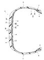
- FIG. 1 is a meridional cross-sectional view of a tire of one embodiment of the present disclosure
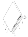
- FIG. 2 is an enlarged perspective view of the band ply of FIG. 1
- 3 is an enlarged perspective view of the band cord of FIG. 2
- FIG. 2 is an enlarged cross-sectional view of a first circumferential groove and a band layer of FIG. 1;
- FIG. 1 shows a meridional cross-sectional view of a pneumatic tire (hereinafter sometimes simply referred to as "tire") 1 of the present embodiment.
- FIG. 1 is a transverse cross-sectional view of the tire 1 in its normal state, including the rotation axis.
- the tire 1 of this embodiment is a pneumatic tire for passenger cars.
- the present disclosure is not limited to such an aspect, and may be applied to tires for heavy loads and tires for motorcycles.
- Regular condition means that, in the case of tires that meet various standards, the tire is mounted on a regular rim, filled with regular internal pressure, and has no load.
- the normal condition means a standard usage condition according to the purpose of use of the tire, which is a condition in which the tire is not mounted on the vehicle and no load is applied.
- a “regular rim” is a rim defined for each tire in a standard system that includes the standard on which the tire is based.
- JATMA is a "standard rim”
- ETRTO it is "Measuring Rim”.
- Regular internal pressure is the air pressure specified for each tire by each standard in the standard system including the standard that the tire is based on. Maximum value described in VARIOUS COLD INFLATION PRESSURES", or “INFLATION PRESSURE” for ETRTO.
- the dimensions of each part of the tire are the values measured in the normal condition. In the case of a component inside the tire that cannot be measured while maintaining its normal state, its dimensions shall be measured while maintaining its shape in said normal state. Further, in this specification, unless otherwise specified, the composition of each part of the tire means the composition of materials taken from a new and unused tire. In addition, as a sampling method at that time, a method that does not change the composition as much as possible is appropriately adopted.
- the tire 1 of this embodiment has a carcass 6.
- the carcass 6 is composed of, for example, one carcass ply 6A.
- the carcass ply 6A includes a plurality of carcass cords and topping rubber covering them.
- the carcass cords are arranged, for example, at an angle of 75 to 90° with respect to the tire circumferential direction. "75 to 90 degrees” means “75 degrees or more and 90 degrees or less", and the same applies hereinafter in the present specification.
- Organic fiber cords such as nylon, polyester, or rayon are preferably used as the carcass cords.
- the carcass ply 6A has a main body portion 6a and a folded portion 6b.
- the body portion 6 a extends from one bead portion 4 to the other bead portion 4 via one sidewall portion 3 , the tread portion 2 , the other sidewall portion 3 .
- the folded portion 6b continues to the main body portion 6a, folds around the bead core 5 from the inner side in the tire axial direction to the outer side, and extends outward in the tire radial direction.
- a belt layer 8 is provided in the tread portion 2 of the present embodiment.
- the belt layer 8 includes, for example, two belt plies 8A and 8B.
- Each of the belt plies 8A, 8B includes, for example, a plurality of belt cords arranged obliquely with respect to the tire circumferential direction and a topping rubber covering them.
- Each belt cord is preferably inclined at an angle of 10 to 45° with respect to the tire circumferential direction.
- the tread portion 2 includes a tread rubber 2G that forms a contact surface, and a band layer 9 arranged inside the tread rubber 2G in the tire radial direction.
- the tread rubber 2G is provided with at least one first circumferential groove 10 continuously extending in the tire circumferential direction along the ground contact surface.
- Three first circumferential grooves 10 are provided in the tread rubber 2G of the present embodiment.
- the groove width of the first circumferential groove 10 is, for example, 3 to 15 mm.
- the depth of the first circumferential groove 10 is, for example, 5-10 mm.
- the groove width and groove depth of the first circumferential groove 10 are not particularly limited as long as a certain degree of drainage can be expected during wet running.
- the tread rubber 2G may be provided with second circumferential grooves different from the first circumferential grooves 10 described above.
- the band layer 9 is composed of, for example, one band ply 11 .
- the band ply 11 also includes a band cord 12 arranged substantially parallel to the tire circumferential direction and a topping rubber 13 covering the band cord 12 .
- the band layer 9 may be formed by, for example, stacking a plurality of band plies 11, or the plurality of band plies 11 may be arranged apart in the tire axial direction.
- the band ply 11 of the present embodiment is configured as a so-called jointless band in which one band cord is wound in the tire circumferential direction, for example.
- the band ply 11 may include a plurality of band cords 12 arranged substantially parallel to the tire circumferential direction.
- the band cord 12 extending substantially parallel to the tire circumferential direction includes at least a mode in which the band cord 12 extends at an angle of 5° or less with respect to the tire circumferential direction.
- the band cord 12 is a hybrid cord in which first filaments 16 and second filaments 17 having a smaller elastic modulus than the first filaments 16 are twisted together.
- the first filament 16 and the second filament 17 are made of organic fibers, and materials such as nylon, aramid, and PET, which have been conventionally used as materials for tire cords, are employed.
- a known hybrid code is appropriately adopted for the band code 12 of the present embodiment.
- FIG. 4 An enlarged view of the first circumferential groove 10 and the band layer 9 is shown in FIG. 4, the belt layer 8 (shown in FIG. 1) arranged radially inward of the band layer 9 is omitted. Also, in FIG. 4, the cross section of the band cord 12 is simplified and indicated by a circle, but it goes without saying that the band cord 12 has the above-described configuration. As shown in FIG. 4, in the present disclosure, the maximum thickness t1 of the topping rubber 13 on the radially outer side of the band cord 12 in the radially inner region of the first circumferential groove 10 is 1.0 mm or less. is.
- the minimum distance d1 from the groove bottom of the first circumferential groove 10 to the outer surface 9s of the band layer 9 in the tire radial direction is 2.0 mm or less. Furthermore, the distance d2 in the tire normal direction from the groove edge 10e of the first circumferential groove 10 to the tire radial direction outer surface 9s of the band layer 9 is 15.0 mm or less.
- the outer surface 9 s of the band layer 9 means the outer surface of the topping rubber 13 covering the band cord 12 .
- the tire normal direction means a direction orthogonal to the ground contact surface of the tread portion 2 .
- the contact surface of the tread portion 2 means the contact surface with the plane when the tire 1 in the normal state is grounded on the plane with a camber angle of 0° under a normal load.
- the groove edge means the boundary between the opening region of the groove and the contact surface. The contact surface and the groove edge can be imaged by a known method such as CT imaging.
- the "regular load” is the load specified for each tire by each standard in the standard system including the standards on which the tire is based. "Load capacity”, the maximum value listed in the table “TIRE LOAD LIMITS AT VARIOUS COLD INFLATION PRESSURES" for TRA, and "LOAD CAPACITY” for ETRTO.
- the "normal load” refers to the load acting on one tire when the tire is in the standard mounting state.
- the “standard mounting state” refers to a state in which the tire is mounted on a standard vehicle according to the purpose of use of the tire, and the vehicle is standing still on a flat road surface in a drivable state.
- the tire 1 of the present disclosure can improve steering stability during high-speed driving while maintaining good ride comfort.
- the reason for this is presumed to be the following mechanism.
- the band layer 9 has a great influence on the degree of vibration absorption of the tread portion 2 and the degree of outer diameter growth of the tread portion 2 .
- the band layer 9 has a great influence on ride comfort during normal running and steering stability during high-speed running.
- a hybrid code is adopted for the band code 12 of this band layer 9 .
- the second filament 17 having a low elastic modulus (shown in FIG. 3, the same applies hereinafter) becomes dominant during normal running when the tread portion 2 has a small outer diameter growth, and good riding comfort is achieved. maintained.
- the first filament 16 shown in FIG. 3, the same shall apply hereinafter
- having a high elastic modulus suppresses the growth of the outer diameter of the tread portion 2, thereby exhibiting excellent steering stability. .
- the developers have found that the steering stability can be further improved by specifying the thickness of the rubber around the band layer 9, and have completed the present disclosure.
- the thickness t1 is 1.0 mm or less
- the distance d1 is 2.0 mm or less
- the distance d2 is 15.0 mm or less.
- the thickness of the rubber outside in the tire radial direction can be set smaller than the band cords 12 included in the band layer 9, and the influence of the centrifugal force acting on the tread part 2 during high-speed running can be reduced. Therefore, the growth of the outer diameter of the tread portion 2 is suppressed, the tread profile can be maintained even during high-speed running, and the ground contact of the tread portion 2 is improved.
- the mechanism described above can improve steering stability during high-speed travel while maintaining good ride comfort.
- the band cord 12 of the present embodiment is formed by twisting a first yarn 18 twisted with a first filament 16 and a second yarn 19 twisted with a second filament 17. Consists of a multi-twisted structure.
- the band cord 12 is not limited to such a mode, and may have a single twist structure including the first filaments 16 and the second filaments 17 .
- the difference in elastic modulus between the first filament 16 and the second filament 17 shall be determined, for example, by the tensile strength specified in JIS L1017.
- the conditions for measuring the tensile strength are not particularly limited as long as the tensile strength of the first filament 16 and the tensile strength of the second filament 17 are measured under the same conditions.
- the total fineness of one band cord 12 is, for example, 4400 dtex or less, preferably 2000-4000 dtex, more preferably 2500-3500 dtex. Such a band cord 12 is useful for improving riding comfort and steering stability in a well-balanced manner.
- the stress ⁇ 1 when the band cord 12 is stretched by 3% is, for example, 0.030 (N/tex) or less.
- the stress ⁇ 1 is preferably 0.005 (N/tex) or more, more preferably 0.010 (N/tex) or more, preferably 0.025 (N/tex) or less, more preferably 0.020 (N/tex) or less.
- Such a band cord 12 can maintain the durability of the tread portion 2 and exhibit excellent ride comfort.
- the stress ⁇ 2 when the band cord 12 is stretched by 5% is, for example, 0.04 (N/tex) or more.
- the stress ⁇ 2 is preferably 0.043 (N/tex) or more, more preferably 0.045 (N/tex) or more, and preferably 0.06 (N/tex) or less, more preferably 0.055 (N/tex) or less.
- Such a band cord 12 is useful for improving ride comfort and steering stability at high speeds in a well-balanced manner.
- the ratio ⁇ 1/ ⁇ 2 (%) between the stress ⁇ 1 and the stress ⁇ 2 is preferably 25% or more, more preferably 29% or more, and preferably 50% or less, more preferably 43% or less.
- the above-mentioned stress ⁇ 1 and stress ⁇ 2 are measured, for example, by the method of measuring the load at constant elongation specified in JIS L1017.
- a plurality of first circumferential grooves 10 are arranged in the tread rubber 2G. Further, the tread rubber 2G is provided with a plurality of lateral grooves (not shown) extending along the tire axial direction on the ground contact surface.
- the sea ratio of the contact surface of the tread portion 2 is preferably 15% or more, more preferably 20% or more, and preferably 50% or less, more preferably 40%. % or less, more preferably 30% or less.
- the sea ratio is the ratio of the sum of the opening areas of all the grooves to the total area of the virtual ground contact surface in a state in which all the grooves arranged on the contact surface of the tread rubber 2G are filled.
- the ratio ⁇ 1/ ⁇ 2 (%) of the stress ⁇ 1 (N/tex) when the band cord 12 is stretched by 3% to the stress ⁇ 2 (N/tex) when the band cord 12 is stretched by 5% is the contact point of the tread portion. It is desirable to be larger than the sea ratio (%) of the ground. Specifically, the ratio ⁇ 1/ ⁇ 2 (%) is preferably 1.50 times or more, more preferably 1.90 times or more, and preferably 3.00 times or less, more than the sea ratio (%). Desirably, it is 2.86 times or less. As a result, the ratio ⁇ 1/ ⁇ 2 is optimized, and excellent steering stability is exhibited both during low-to-medium speed running and high speed running.
- the tread rubber 2G contains, for example, a rubber composition having a complex elastic modulus E*1 of 10 to 20 (MPa) at 30°C.
- the complex elastic modulus E*1 is more preferably 12 to 18 (MPa).
- the complex elastic modulus E*1 at 30° C. of the tread rubber 2G may be 10 (MPa) or less.
- the complex elastic modulus E*1 is a value measured using a “viscoelastic spectrometer” manufactured by Iwamoto Seisakusho Co., Ltd. under the following conditions in accordance with JIS-K6394.
- a rubber piece obtained from the tread rubber 2G so that the long side is in the tire circumferential direction, the short side is in the tire axial direction, and the thickness is in the tire radial direction is adopted.
- the size of the rubber piece is, for example, 20 mm long side ⁇ 4 mm short side ⁇ 1 mm thick.
- the developers found that specifying the complex elastic modulus E*1 of the tread rubber 2G according to the sea ratio can contribute to both ride comfort and steering stability.
- the product of the complex elastic modulus E*1 (MPa) and the sea ratio (%) is preferably 3.0 (MPa) or more, more preferably 4.3 (MPa) or more. , preferably 9.0 (MPa) or less, more preferably 7.5 (MPa) or less.
- the product ⁇ 2 E*1 of the stress ⁇ 2 (N/tex) at 5% elongation of the band cord and the complex elastic modulus E*1 (MPa) is preferably 0.45 (N MPa/tex ) or more, more preferably 0.60 (N MPa/tex) or more, preferably 1.05 (N MPa/tex) or less, more preferably 0.90 (N MPa/tex) or less .
- the amount of deformation of the tread portion 2 and the band layer 9 during high-speed running is optimized, and ride comfort and steering stability are improved in a well-balanced manner.
- the thickness t1 is preferably 0.05 mm or more, more preferably 0.10 mm or more, and preferably 0.50 mm or less, more preferably 0.30 mm or less.
- the distance d1 is desirably 0.5 mm or more, more desirably 1.0 mm or more, and desirably 1.8 mm or less, more desirably 1.5 mm or less.
- the thickness of the rubber is optimized at the groove bottom of the first circumferential groove 10, and the above-described effects are exhibited more reliably.
- the distance d2 is desirably 5.0 mm or more, more desirably 7.0 mm or more, desirably 12.0 mm or less, more desirably 10.0 mm or less. Thereby, the thickness of the tread rubber 2G is optimized.
- the product ⁇ 1 ⁇ d2 of the stress ⁇ 1 (N/tex) and the distance d2 (mm) is preferably 0.05 to 0.40 (N ⁇ mm/tex). 0.08 to 0.18 is more desirable.
- the amount of deformation of the tread portion 2 during medium to low speed running is optimized, and ride comfort can be further improved.
- the steering stability is further improved by specifying the stress ⁇ 2 when the band cord 12 is stretched by 5% and the distance d2 in association with each other.
- the product ⁇ 2 ⁇ d2 of the stress ⁇ 2 (N/tex) and the distance d2 (mm) is preferably 0.30 to 0.60 (N ⁇ mm/tex). More preferably, it is between 0.35 and 0.50.
- a ratio t1/d1 (%) between the thickness t1 and the distance d1 is preferably 5% or more, more preferably 6.7% or more, and preferably 46.2% or less, more preferably 30.8. % or less. Moreover, it is desirable that the ratio t1/d1 (%) between the thickness t1 and the distance d1 is smaller than the shear ratio (%). Specifically, the ratio t1/d1 (%) is preferably 0.15 times or more, more preferably 0.26 times or more, and preferably 0.77 times or less, more than the sea ratio (%). Desirably, it is 0.67 times or less. As a result, the thickness t1 is optimized, and while the durability of the band layer 9 is maintained, ride comfort is improved.
- the distance d1 and the complex elastic modulus E*1 have a large effect on ride comfort and steering stability. It has turned out to be desirable to define in association.
- the product of the distance d1 (mm) and the complex elastic modulus E*1 (MPa) is preferably 12.0 (MPa ⁇ mm) or more, more preferably 15.0 (MPa ⁇ mm). It is more than or equal to, preferably 30.0 (MPa ⁇ mm) or less, more preferably 22.5 (MPa ⁇ mm) or less.
- the tread rubber 2G of the present embodiment is provided with three first circumferential grooves 10, and at least one first circumferential groove 10 has the above configuration. .
- all of the plurality of first circumferential grooves 10 arranged in the tread rubber 2G have the above configuration. As a result, the above-described effects can be reliably exhibited.
- a pneumatic tire of size 215/60R16 satisfying the requirements of the present disclosure was prototyped based on the specifications in Tables 1-4.
- Comparative Example 1 a pneumatic tire having a hybrid cord as a band cord and having a thickness t1, a distance d1 and a distance d2 that did not satisfy the requirements of the present disclosure was fabricated.
- Comparative Example 2 a pneumatic tire was experimentally produced in which the material of the band cord was composed only of nylon and the thickness t1, the distance d1 and the distance d2 did not satisfy the requirements of the present disclosure.
- the tires of Comparative Examples 1 and 2 have substantially the same configuration as the tires of Examples except for the specifications shown in Tables 1-4. Each test tire was tested for ride comfort and steering stability at high speeds.
- the common specifications of test tires and test methods are as follows. Mounting rim: 16 x 6.5J Internal pressure: 210kPa Displacement of test vehicle: 2000cc Drive system: FF Test tire mounting position: All wheels
- Riding comfort was evaluated by the following method when the test vehicle was run on a general road. Each of 20 test drivers conducted a test drive test, and the riding comfort was scored from 1 to 10 points for each test driver (the higher the number, the better), and the total score of the 20 test drivers was calculated. was done. The results are indicated by a score with the sum of the above-mentioned scoring results of Comparative Example 1 being 100, and the larger the value, the better the riding comfort.
- Steering stability at high speed was evaluated by the following method when the test vehicle was run at high speed.
- Each of the 20 test drivers conducted a test drive test, and the steering stability was scored from 1 to 10 points for each test driver (the higher the number, the better), and the total score of the 20 test drivers was calculated. was done. The results are indicated by a score with the sum of the score results of Comparative Example 1 being 100, and the larger the value, the better the steering stability during high-speed running.
- a pneumatic tire having a tread portion includes a tread rubber that forms a ground contact surface and a band layer arranged radially inward of the tread rubber,
- the tread rubber is provided with a first circumferential groove extending continuously in the tire circumferential direction on the ground contact surface
- the band layer includes a band cord arranged substantially parallel to the tire circumferential direction and a topping rubber covering the band cord,
- the band cord is a hybrid cord obtained by twisting a first filament and a second filament having a lower elastic modulus than the first filament, a maximum thickness t1 of the topping rubber outside the band cord in the tire radial direction is 1.0 mm or less in a region radially inside the first circumferential groove, the minimum distance d1 from the bottom of the first circumferential groove to the outer surface of the band layer in the tire radial direction is 2.0 mm or less, A distance d2 in the tire normal direction from the groove edge of the first circumferential groove to the outer surface of the band layer in the tire radi
- the ratio ⁇ 1/ ⁇ 2 (%) of the stress ⁇ 1 (N/tex) at 3% elongation of the band cord to the stress ⁇ 2 (N/tex) at 5% elongation of the band cord is the contact point of the tread portion. 14.
- the thickness t1 is 0.05 to 0.30 mm
- the distance d1 is 0.5 to 1.5 mm
Landscapes
- Engineering & Computer Science (AREA)
- Mechanical Engineering (AREA)
- Tires In General (AREA)
Priority Applications (4)
| Application Number | Priority Date | Filing Date | Title |
|---|---|---|---|
| EP22791391.0A EP4173844B1 (en) | 2021-04-22 | 2022-03-09 | Pneumatic tire |
| JP2023516324A JP7838576B2 (ja) | 2021-04-22 | 2022-03-09 | 空気入りタイヤ |
| CN202280006824.2A CN116323253B (zh) | 2021-04-22 | 2022-03-09 | 充气轮胎 |
| US18/286,444 US12330451B2 (en) | 2021-04-22 | 2022-03-09 | Pneumatic tire |
Applications Claiming Priority (2)
| Application Number | Priority Date | Filing Date | Title |
|---|---|---|---|
| JP2021-072796 | 2021-04-22 | ||
| JP2021072796 | 2021-04-22 |
Publications (1)
| Publication Number | Publication Date |
|---|---|
| WO2022224610A1 true WO2022224610A1 (ja) | 2022-10-27 |
Family
ID=83722833
Family Applications (1)
| Application Number | Title | Priority Date | Filing Date |
|---|---|---|---|
| PCT/JP2022/010235 Ceased WO2022224610A1 (ja) | 2021-04-22 | 2022-03-09 | 空気入りタイヤ |
Country Status (5)
| Country | Link |
|---|---|
| US (1) | US12330451B2 (https=) |
| EP (1) | EP4173844B1 (https=) |
| JP (1) | JP7838576B2 (https=) |
| CN (1) | CN116323253B (https=) |
| WO (1) | WO2022224610A1 (https=) |
Families Citing this family (1)
| Publication number | Priority date | Publication date | Assignee | Title |
|---|---|---|---|---|
| FR3159556A1 (fr) * | 2024-02-23 | 2025-08-29 | Compagnie Generale Des Etablissements Michelin | Pneumatique comprenant une bande de roulement complexe résistante à l’usure |
Citations (4)
| Publication number | Priority date | Publication date | Assignee | Title |
|---|---|---|---|---|
| JPH04314604A (ja) * | 1991-04-11 | 1992-11-05 | Yokohama Rubber Co Ltd:The | 乗用車用空気入りラジアルタイヤ |
| JP2011218980A (ja) * | 2010-04-09 | 2011-11-04 | Toyo Tire & Rubber Co Ltd | 空気入りラジアルタイヤ |
| US20150273954A1 (en) * | 2014-03-26 | 2015-10-01 | American Engineering Group LLC | Zero-pressure tire |
| JP2018154075A (ja) | 2017-03-21 | 2018-10-04 | 住友ゴム工業株式会社 | 空気入りタイヤの製造方法 |
Family Cites Families (33)
| Publication number | Priority date | Publication date | Assignee | Title |
|---|---|---|---|---|
| JP3322934B2 (ja) | 1993-03-09 | 2002-09-09 | 横浜ゴム株式会社 | 空気入りラジアルタイヤ |
| DE69403315T2 (de) * | 1993-12-28 | 1997-08-28 | Sumitomo Rubber Ind | Radialer Luftreifen |
| JP2966748B2 (ja) * | 1994-03-08 | 1999-10-25 | 住友ゴム工業株式会社 | 空気入りタイヤ |
| JPH08142609A (ja) * | 1994-11-18 | 1996-06-04 | Ohtsu Tire & Rubber Co Ltd :The | 空気入りタイヤ |
| US6082423A (en) | 1997-06-09 | 2000-07-04 | The Goodyear Tire & Rubber Company | Low cost light weight radial tire |
| US6530405B1 (en) | 1998-08-26 | 2003-03-11 | The Goodyear Tire & Rubber Company | On/off-road tread |
| US6601378B1 (en) * | 1999-09-08 | 2003-08-05 | Honeywell International Inc. | Hybrid cabled cord and a method to make it |
| JP2001347809A (ja) | 2000-06-05 | 2001-12-18 | Sumitomo Rubber Ind Ltd | 空気入りタイヤ |
| JP4456386B2 (ja) | 2004-03-22 | 2010-04-28 | 住友ゴム工業株式会社 | 空気入りタイヤ |
| US7484545B2 (en) | 2005-12-20 | 2009-02-03 | The Goodyear Tire & Rubber Co. | Radial tire for aircraft with specified merged cords |
| JP4478646B2 (ja) | 2005-12-21 | 2010-06-09 | 住友ゴム工業株式会社 | 空気入りタイヤ |
| EP2581239A1 (en) * | 2006-01-20 | 2013-04-17 | The Yokohama Rubber Co., Ltd. | Pneumatic tire |
| JP5075688B2 (ja) | 2007-05-02 | 2012-11-21 | 住友ゴム工業株式会社 | 自動二輪車用タイヤ |
| JP2009052158A (ja) | 2007-08-24 | 2009-03-12 | Bridgestone Corp | コードとゴムの複合体及びそれを用いた空気入りタイヤ |
| JP2009137403A (ja) | 2007-12-05 | 2009-06-25 | Sumitomo Rubber Ind Ltd | 空気入りラジアルタイヤ |
| JP4829994B2 (ja) | 2009-04-06 | 2011-12-07 | 住友ゴム工業株式会社 | 空気入りタイヤ |
| JP5206754B2 (ja) * | 2010-09-09 | 2013-06-12 | 横浜ゴム株式会社 | 空気入りタイヤ |
| JP5602037B2 (ja) | 2011-01-31 | 2014-10-08 | 住友ゴム工業株式会社 | 自動車用タイヤのコーナリング性能の予測方法 |
| WO2012141158A1 (ja) | 2011-04-11 | 2012-10-18 | 住友ゴム工業株式会社 | 空気入りタイヤ |
| JP5395882B2 (ja) * | 2011-12-01 | 2014-01-22 | 住友ゴム工業株式会社 | 空気入りタイヤ |
| JP5650690B2 (ja) * | 2012-06-12 | 2015-01-07 | 住友ゴム工業株式会社 | トレッド用ゴム組成物及び空気入りタイヤ |
| JP5957405B2 (ja) | 2013-03-19 | 2016-07-27 | 住友ゴム工業株式会社 | 空気入りタイヤ |
| CN105324252B (zh) | 2013-07-05 | 2018-11-16 | 住友橡胶工业株式会社 | 充气轮胎 |
| JP6661949B2 (ja) * | 2015-10-06 | 2020-03-11 | 横浜ゴム株式会社 | 空気入りタイヤ |
| DE102016216082A1 (de) | 2016-08-26 | 2018-03-01 | Continental Reifen Deutschland Gmbh | Festigkeitsträgerlage für elastomere Erzeugnisse, insbesondere für eine Karkasslage eines Fahrzeugluftreifens, aufweisend einen Hybridcord |
| DE102016216081A1 (de) | 2016-08-26 | 2018-03-01 | Continental Reifen Deutschland Gmbh | Festigkeitsträgerlage für elastomere Erzeugnisse, insbesondere für eine Karkasslage eines Fahrzeugluftreifens, aufweisend einen Hybridcord |
| JP6848319B2 (ja) | 2016-10-06 | 2021-03-24 | 横浜ゴム株式会社 | 空気入りタイヤ |
| JP6822170B2 (ja) | 2017-01-24 | 2021-01-27 | 住友ゴム工業株式会社 | 空気入りタイヤ |
| CN107444025B (zh) | 2017-08-09 | 2020-06-12 | 安徽佳通乘用子午线轮胎有限公司 | 具有鱼骨式花纹块的轮胎 |
| DE102017222606A1 (de) | 2017-12-13 | 2019-06-13 | Continental Reifen Deutschland Gmbh | Festigkeitsträgerlage und Fahrzeugluftreifen |
| CN111791649B (zh) | 2019-04-03 | 2024-02-13 | 住友橡胶工业株式会社 | 轮胎 |
| JP6863503B1 (ja) | 2020-04-24 | 2021-04-21 | 住友ゴム工業株式会社 | タイヤ |
| FR3118605B1 (fr) | 2021-01-07 | 2022-12-30 | Michelin & Cie | Pneumatique comprenant une couche de frettage à trame hydrophobe et à sommet d’épaisseur réduite |
-
2022
- 2022-03-09 WO PCT/JP2022/010235 patent/WO2022224610A1/ja not_active Ceased
- 2022-03-09 US US18/286,444 patent/US12330451B2/en active Active
- 2022-03-09 CN CN202280006824.2A patent/CN116323253B/zh active Active
- 2022-03-09 JP JP2023516324A patent/JP7838576B2/ja active Active
- 2022-03-09 EP EP22791391.0A patent/EP4173844B1/en active Active
Patent Citations (4)
| Publication number | Priority date | Publication date | Assignee | Title |
|---|---|---|---|---|
| JPH04314604A (ja) * | 1991-04-11 | 1992-11-05 | Yokohama Rubber Co Ltd:The | 乗用車用空気入りラジアルタイヤ |
| JP2011218980A (ja) * | 2010-04-09 | 2011-11-04 | Toyo Tire & Rubber Co Ltd | 空気入りラジアルタイヤ |
| US20150273954A1 (en) * | 2014-03-26 | 2015-10-01 | American Engineering Group LLC | Zero-pressure tire |
| JP2018154075A (ja) | 2017-03-21 | 2018-10-04 | 住友ゴム工業株式会社 | 空気入りタイヤの製造方法 |
Also Published As
| Publication number | Publication date |
|---|---|
| EP4173844A1 (en) | 2023-05-03 |
| CN116323253B (zh) | 2025-10-21 |
| CN116323253A (zh) | 2023-06-23 |
| US20240190177A1 (en) | 2024-06-13 |
| JPWO2022224610A1 (https=) | 2022-10-27 |
| EP4173844B1 (en) | 2025-01-15 |
| EP4173844A4 (en) | 2024-01-17 |
| US12330451B2 (en) | 2025-06-17 |
| JP7838576B2 (ja) | 2026-04-01 |
Similar Documents
| Publication | Publication Date | Title |
|---|---|---|
| JP3113592B2 (ja) | 空気入りラジアルタイヤ | |
| JP4377933B2 (ja) | 空気入りタイヤ | |
| JP5756486B2 (ja) | 空気入りタイヤ | |
| JP5841383B2 (ja) | 空気入りタイヤ | |
| JP6423312B2 (ja) | タイヤ用補強部材およびこれを用いたタイヤ | |
| JP7388056B2 (ja) | 空気入りタイヤ | |
| EP1097824A2 (en) | Radial tyre for motorcycle | |
| JP2023021772A (ja) | 空気入りタイヤ | |
| US20220324258A1 (en) | Pneumatic tire | |
| EP1612058A1 (en) | Motorcycle tyre | |
| JP7067356B2 (ja) | 空気入りタイヤ | |
| US12330451B2 (en) | Pneumatic tire | |
| JP7842521B2 (ja) | タイヤ | |
| JP2003146029A (ja) | 空気入りラジアルタイヤ | |
| JP4002113B2 (ja) | 空気入りタイヤ | |
| JP6790547B2 (ja) | 空気入りタイヤ | |
| CN113474184B (zh) | 充气轮胎 | |
| JP2018039276A (ja) | 空気入りタイヤ | |
| JP6953938B2 (ja) | 空気入りタイヤ | |
| JP6529127B2 (ja) | 空気入りタイヤ | |
| JP5917989B2 (ja) | 空気入りタイヤ | |
| JP6192491B2 (ja) | 空気入りタイヤ | |
| JP2011098637A (ja) | 空気入りタイヤ | |
| JP2011051497A (ja) | 空気入りラジアルタイヤ | |
| JP2025076168A (ja) | 二輪車用タイヤ |
Legal Events
| Date | Code | Title | Description |
|---|---|---|---|
| 121 | Ep: the epo has been informed by wipo that ep was designated in this application |
Ref document number: 22791391 Country of ref document: EP Kind code of ref document: A1 |
|
| ENP | Entry into the national phase |
Ref document number: 2022791391 Country of ref document: EP Effective date: 20230130 |
|
| ENP | Entry into the national phase |
Ref document number: 2023516324 Country of ref document: JP Kind code of ref document: A |
|
| WWE | Wipo information: entry into national phase |
Ref document number: 18286444 Country of ref document: US |
|
| NENP | Non-entry into the national phase |
Ref country code: DE |
|
| WWG | Wipo information: grant in national office |
Ref document number: 18286444 Country of ref document: US |
|
| WWG | Wipo information: grant in national office |
Ref document number: 202280006824.2 Country of ref document: CN |