EP1097824A2 - Radial tyre for motorcycle - Google Patents
Radial tyre for motorcycle Download PDFInfo
- Publication number
- EP1097824A2 EP1097824A2 EP00309675A EP00309675A EP1097824A2 EP 1097824 A2 EP1097824 A2 EP 1097824A2 EP 00309675 A EP00309675 A EP 00309675A EP 00309675 A EP00309675 A EP 00309675A EP 1097824 A2 EP1097824 A2 EP 1097824A2
- Authority
- EP
- European Patent Office
- Prior art keywords
- band
- elongation
- cord
- tyre
- carcass
- Prior art date
- Legal status (The legal status is an assumption and is not a legal conclusion. Google has not performed a legal analysis and makes no representation as to the accuracy of the status listed.)
- Withdrawn
Links
Images


Classifications
-
- D—TEXTILES; PAPER
- D07—ROPES; CABLES OTHER THAN ELECTRIC
- D07B—ROPES OR CABLES IN GENERAL
- D07B1/00—Constructional features of ropes or cables
- D07B1/06—Ropes or cables built-up from metal wires, e.g. of section wires around a hemp core
- D07B1/0606—Reinforcing cords for rubber or plastic articles
- D07B1/0613—Reinforcing cords for rubber or plastic articles the reinforcing cords being characterised by the rope configuration
-
- B—PERFORMING OPERATIONS; TRANSPORTING
- B60—VEHICLES IN GENERAL
- B60C—VEHICLE TYRES; TYRE INFLATION; TYRE CHANGING; CONNECTING VALVES TO INFLATABLE ELASTIC BODIES IN GENERAL; DEVICES OR ARRANGEMENTS RELATED TO TYRES
- B60C9/00—Reinforcements or ply arrangement of pneumatic tyres
- B60C9/18—Structure or arrangement of belts or breakers, crown-reinforcing or cushioning layers
- B60C9/20—Structure or arrangement of belts or breakers, crown-reinforcing or cushioning layers built-up from rubberised plies each having all cords arranged substantially parallel
- B60C9/2003—Structure or arrangement of belts or breakers, crown-reinforcing or cushioning layers built-up from rubberised plies each having all cords arranged substantially parallel characterised by the materials of the belt cords
- B60C9/2006—Structure or arrangement of belts or breakers, crown-reinforcing or cushioning layers built-up from rubberised plies each having all cords arranged substantially parallel characterised by the materials of the belt cords consisting of steel cord plies only
-
- B—PERFORMING OPERATIONS; TRANSPORTING
- B60—VEHICLES IN GENERAL
- B60C—VEHICLE TYRES; TYRE INFLATION; TYRE CHANGING; CONNECTING VALVES TO INFLATABLE ELASTIC BODIES IN GENERAL; DEVICES OR ARRANGEMENTS RELATED TO TYRES
- B60C9/00—Reinforcements or ply arrangement of pneumatic tyres
- B60C9/18—Structure or arrangement of belts or breakers, crown-reinforcing or cushioning layers
- B60C9/20—Structure or arrangement of belts or breakers, crown-reinforcing or cushioning layers built-up from rubberised plies each having all cords arranged substantially parallel
- B60C9/22—Structure or arrangement of belts or breakers, crown-reinforcing or cushioning layers built-up from rubberised plies each having all cords arranged substantially parallel the plies being arranged with all cords disposed along the circumference of the tyre
- B60C9/2204—Structure or arrangement of belts or breakers, crown-reinforcing or cushioning layers built-up from rubberised plies each having all cords arranged substantially parallel the plies being arranged with all cords disposed along the circumference of the tyre obtained by circumferentially narrow strip winding
-
- D—TEXTILES; PAPER
- D07—ROPES; CABLES OTHER THAN ELECTRIC
- D07B—ROPES OR CABLES IN GENERAL
- D07B1/00—Constructional features of ropes or cables
- D07B1/06—Ropes or cables built-up from metal wires, e.g. of section wires around a hemp core
- D07B1/0606—Reinforcing cords for rubber or plastic articles
- D07B1/0646—Reinforcing cords for rubber or plastic articles comprising longitudinally preformed wires
-
- D—TEXTILES; PAPER
- D07—ROPES; CABLES OTHER THAN ELECTRIC
- D07B—ROPES OR CABLES IN GENERAL
- D07B2201/00—Ropes or cables
- D07B2201/10—Rope or cable structures
- D07B2201/1028—Rope or cable structures characterised by the number of strands
- D07B2201/1032—Rope or cable structures characterised by the number of strands three to eight strands respectively forming a single layer
-
- D—TEXTILES; PAPER
- D07—ROPES; CABLES OTHER THAN ELECTRIC
- D07B—ROPES OR CABLES IN GENERAL
- D07B2201/00—Ropes or cables
- D07B2201/10—Rope or cable structures
- D07B2201/104—Rope or cable structures twisted
-
- D—TEXTILES; PAPER
- D07—ROPES; CABLES OTHER THAN ELECTRIC
- D07B—ROPES OR CABLES IN GENERAL
- D07B2201/00—Ropes or cables
- D07B2201/20—Rope or cable components
- D07B2201/2015—Strands
- D07B2201/2022—Strands coreless
-
- D—TEXTILES; PAPER
- D07—ROPES; CABLES OTHER THAN ELECTRIC
- D07B—ROPES OR CABLES IN GENERAL
- D07B2201/00—Ropes or cables
- D07B2201/20—Rope or cable components
- D07B2201/2015—Strands
- D07B2201/2024—Strands twisted
-
- D—TEXTILES; PAPER
- D07—ROPES; CABLES OTHER THAN ELECTRIC
- D07B—ROPES OR CABLES IN GENERAL
- D07B2201/00—Ropes or cables
- D07B2201/20—Rope or cable components
- D07B2201/2015—Strands
- D07B2201/2036—Strands characterised by the use of different wires or filaments
-
- D—TEXTILES; PAPER
- D07—ROPES; CABLES OTHER THAN ELECTRIC
- D07B—ROPES OR CABLES IN GENERAL
- D07B2201/00—Ropes or cables
- D07B2201/20—Rope or cable components
- D07B2201/2015—Strands
- D07B2201/2038—Strands characterised by the number of wires or filaments
- D07B2201/2039—Strands characterised by the number of wires or filaments three to eight wires or filaments respectively forming a single layer
Definitions
- the present invention relates to a pneumatic tyre, more particularly to a radial tyre for motorcycles having a tread band capable of improving the high-speed straight-running stability and traction during high speed cornering.
- an object of the present invention to provide a radial tyre for motorcycles, in which sufficient traction can be obtained during cornering to improve cornering performance, and the high speed straight running stability is also improved at the same time.
- a radial tyre for motorcycles comprises a tread portion with tread edges, a pair of sidewall portions, a pair of bead portions, a carcass comprising a radial ply, and a band disposed radially outside the carcass in the tread portion, the tread portion being curved so that the maximum tyre section width lies between the tread edges, and the band made of spirally wound cords, each cord having a variable tension modulus which continuously increases from its zero elongation to 1.0 % elongation.
- the elongation at rupture of the band cord is not more than 4.0 %.
- the bending rigidity index of the band defined as the product of a bending rigidity of a band cord and the band cord count per 5 cm width is in a range of from 300 to 600 gram centimetre.
- a radial tyre 1 is for the rear wheel of a large-size motorcycle.
- the tyre 1 comprises a tread portion 2 with tread edges Te, a pair of axially spaced bead portions 4, and a pair of sidewall portions 3 extending between the tread edges Te and bead portions.
- the tread portion 2 is curved so that the maximum tyre section width WT lies between the tread edges Te.
- the tread face 2S has a relatively small radius of curvature in comparison with passenger car tyres for example.
- the tyre 1 further comprises a carcass 6 extending between the bead portions 4, and a band 7 disposed radially outside the carcass 6 in the tread portion 2.
- the carcass 6 comprises a ply 6A of cords arranged radially at an angle of from 70 to 90 degrees with respect to the tyre equator and extending between the bead portions 4 through the tread portion 2 and sidewall portions 3 and turned up around the bead core 5 in each bead portion 4 from the inside to the outside of the tyre so as to form a pair of turnup portions and a main portion therebetween.
- organic fibre cords e.g. nylon, polyester, rayon, aromatic polyamide and the like are used.
- bead apex 8 made of hard rubber tapering radially outward from the bead core 5.
- the carcass 6 comprises a single ply 6A of nylon fibre cords arranged radially at 90 degrees.
- the turnup portion is extended radially outwardly beyond the radially outer end of the bead apex and terminates at a short distance therefrom. But, it is also possible to terminate it near the tread edge Te to increase the tyre lateral stiffness.
- the band 7 is made of spirally wound cords 11 and disposed along the radially outside of the carcass 6. With respect to the tyre equator, the cord angle is almost zero or a very small value of five degrees at most.
- the axial width WB of the band 7 is set in the range of from 0.8 to 0.95 times the maximum tyre section width WT.
- the band cords 11 are wound into a single layer 7a. In other words, the band 7 has a single ply structure.
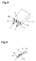
- the band 7 is formed by spirally winding a tape 10 of rubber 12 in which the band cords 11 are embedded in parallel with each other along the length thereof as shown in Fig.2.
- the band cords 11 are embedded in parallel with each other along the length thereof as shown in Fig.2.
- two parallel band cords 11 are embedded.
- a tape 10 is wound continuously from one of the tread edges Te to the other on the radially outer surface of the carcass 6.
- another arrangement is also possible, for example, winding a plurality of tapes 10 spirally from the tyre equator C to the tread edges Te.
- side edges 10a thereof 10 can be overlapped as shown in Fig.3 to prevent loosening.
- the tension at rupture of the band cord 11 is set in the range of not less than 350 N.
- the elongation at rupture of the band cord 11 is set in a range of not more than 4%.
- the band cord 11 has a specific variable tension modulus which continuously increases from its zero elongation to 1.0 % elongation at least in this range.
- the maximum tension modulus occurs at an elongation above 1.0 %, preferably in a range of from 1.3 to 1.8 %. From the elongation at the maximum tension modulus to the elongation at rupture, the tension modulus continuously decreases.
- the tension-elongation curve of such a cord 11 is, as shown in Fig.5 made up of a concave curve from the origin 0 to the inflection point P and a convex curve from the inflection point P. Thus, it has a S-shape. At the inflection point P, the tension modulus becomes maximum. In the range of from 0 to 1.0 % elongation at least, the load-elongation curve is a continuous concave curve having no straight part.
- the band 7 preferably has a bending rigidity index in the range of from 300 to 600 gram centimetre, wherein the bending rigidity index is the product G x N of the bending rigidity G of a band cord and the count N of the band cords per 5 cm width.
- the bending rigidity G is defined as a force in gram centimetre required to bend a cord 15 degrees, which is measured with a V-5 stiffness tester model 150-D of Taber Industries, U.S.A.
- the cord count N when the band 7 is composed of two or more plies 7a, the count N is accordingly the summation of the cord counts of all the plies 7a.
- the bending rigidity index is less than 300 gram centimetre, the tyre rigidity becomes insufficient, and the cornering performance is not fully improved. If the bending rigidity index is more than 600 gram centimetre, the tyre rigidity becomes too high, and the ride comfort deteriorates.
- the band cord 11 is composed of steel filaments 13 twisted together.
- the cord has a 3 x 3 structure, namely, three steel filaments 13 are first twisted together into a strand 14, and three strands 14 are secondly twisted together into a cord 11.
- the three steel filaments 13 in each strand 14 include at least one waved filament 13A as shown in Fig.5. More concretely, each strand 14 is composed of one waved filament 13A and two non-waved filaments 13B or two waved filaments 13A and one non-waved filament 13B.
- the non-waved filament 13B is a straight filament before twisted together.
- the waved filament 13A is a non-straight filament waved two-dimensionally or three-dimensionally (spirally) before twisted together.
- Such a 3 x 3 structure is preferable because the cord can be formed compactly in comparison with 3 x 7, 3 x 4, 4 x 4 structures, and the bending rigidity is high for the tension modulus.
- the band cords 11 are a steel cord, the bending rigidity of the tread portion is, like organic fibre cords, prevented from increasing excessively. Therefore, vibrations during high-speed straight running are controlled, and ride comfort is also improved.
- the bending rigidity of the band cord is high in comparison with an organic fibre cord, the tyre is provided with rigidity which makes it possible to obtain sufficient traction during cornering, and the cornering performance can be improved.
- the tension modulus continuously changes, if running conditions such as the tyre load, running speed, bank angle and the like are changed, abrupt changing of tyre characteristics can be prevented. Thus, handling, running safety and the like are improved.
- Test tyres of size 180/55ZR17 (Rim size:17XMT5.50) having the structure shown in Fig.1 and specifications shown in Table 1 were made and tested as follows.
- a motorcycle (750cc 4-stroke engine) provided on the rear wheel with the test tyre inflated to 250 kPa was run on a dry asphalt road on a tyre test course, and during straight running and cornering at high speed, high speed stability, nimbleness in handling, ride comfort and cornering grip were evaluated into five ranks by the test rider. The larger the rank number, the better the performance. Test results are shown in Table 1.
- the specifications of the front tyre are shown in Table 2.
- the tension-elongation curves of the band cords are shown in Fig.5.
- the band is made of steel cords having specific elongation characteristics, sufficient traction can be obtained during cornering to improve the cornering performance, while displaying advantages of a spiral cord band structure such as good high speed stability.
- the present invention can be suitably applied to a rear tyre for large-size motorcycles.
Landscapes
- Engineering & Computer Science (AREA)
- Mechanical Engineering (AREA)
- Tires In General (AREA)
Abstract
Description
| Tyre | Ref.1 | Ex.1 | Ex.2 | Ex.3 | Ex.4 | |||||
| Carcass | ||||||||||
| Ply number | 1 | 1 | 1 | 1 | 1 | |||||
| | nylon | 2/ | nylon | 2/ | nylon | 2/ | nylon | 2/ | nylon | 2/1440dtex |
| Cord angle (deg.) | 90 | 90 | 90 | 90 | 90 | |||||
| Cord count (/5cm) | 38 | 38 | 38 | 38 | 38 | |||||
| Bead apex height (mm) | 20 | 20 | 20 | 20 | 10 | |||||
| Band | ||||||||||
| Ply number | 1 | 1 | 1 | 1 | 1 | |||||
| Structure | spiral | spiral | spiral | spiral | spiral | |||||
| Cord material | | steel 3X3X0.20 | steel 3X3X0.17 | steel 3X3X0.15 | steel 3X3X0.17 | |||||
| Cord count (/5cm) | 50 | 38 | 38 | 38 | 38 | |||||
| Bending rigidity index (g cm) | 740 | 430 | 330 | 430 | ||||||
| | 4 | 3.7 | 3.9 | 4 | 4 | |||||
| Cornering grip | 3.5 | 3.75 | 3.75 | 4 | 4.1 | |||||
| | 4 | 3.5 | 4 | 3.9 | 4 | |||||
| Nimbleness in handling | 4 | 3.7 | 3.9 | 4 | 4.1 |
| Tyre size | 120/70ZR17 | |
| | ||
| Ply number | ||
| 2 | ||
| | nylon | 2/1440 dtex |
| Cord angle (deg.) | 88 | |
| Cord count (/5cm) | 41 | |
| Breaker | ||
| Ply number | 2(cross ply structure) | |
| Cord material | | |
| Cord angle (deg.) | 17 | |
| Cord count (/5cm) | 35 | |
| Inner pressure | 250kPa | |
| Rim size | 17XMT3.50 |
Claims (5)
- A radial tyre (1) for a motorcycle comprising a tread portion (2) with tread edges (Te), a pair of sidewall portions (3), a pair of bead portions (4), a carcass (6) comprising a radial ply, a band (7) disposed radially outside the carcass (6) in the tread portion (2), said tread portion (2) being curved so that the maximum tyre section width (Wt) lies between the tread edges (Te), and said band (7) being made of spirally wound cords (11), characterised in that each said cord (11) has a variable tension modulus which continuously increases from its zero elongation to 1.0 % elongation.
- A radial tyre according to claim 1, characterised in that the elongation at rupture of the band cord (11) is not more than 4.0 %.
- A radial tyre according to claim 1, characterised in that an elongation at which the tension modulus becomes maximum is in a range of from 1.3 to 1.8 %.
- A radial tyre according to claim 2, characterised in that an elongation at which the tension modulus becomes maximum is in a range of from 1.3 to 1.8 %, and from this elongation to the elongation at rupture, the tension modulus continuously decreases.
- A radial tyre according to claim 1, 2 or 3, characterised in that a bending rigidity index of the band (7) which is defined as the product of a bending rigidity in gram centimetre of a band cord and the band cord count per 5 cm width is in a range of from 300 to 600 gram centimetre.
Applications Claiming Priority (2)
| Application Number | Priority Date | Filing Date | Title |
|---|---|---|---|
| JP31299399 | 1999-11-02 | ||
| JP31299399A JP2001130218A (en) | 1999-11-02 | 1999-11-02 | Radial tire for motorcycle |
Publications (2)
| Publication Number | Publication Date |
|---|---|
| EP1097824A2 true EP1097824A2 (en) | 2001-05-09 |
| EP1097824A3 EP1097824A3 (en) | 2001-11-21 |
Family
ID=18035953
Family Applications (1)
| Application Number | Title | Priority Date | Filing Date |
|---|---|---|---|
| EP00309675A Withdrawn EP1097824A3 (en) | 1999-11-02 | 2000-11-01 | Radial tyre for motorcycle |
Country Status (2)
| Country | Link |
|---|---|
| EP (1) | EP1097824A3 (en) |
| JP (1) | JP2001130218A (en) |
Cited By (7)
| Publication number | Priority date | Publication date | Assignee | Title |
|---|---|---|---|---|
| EP1270270A1 (en) * | 2001-06-29 | 2003-01-02 | Sumitomo Rubber Industries Ltd. | Pneumatic tire |
| FR2834932A1 (en) * | 2002-01-23 | 2003-07-25 | Continental Ag | TIRE FOR VEHICLES, ESPECIALLY FOR MOTORCYCLES |
| EP1486354A1 (en) * | 2003-06-12 | 2004-12-15 | Sumitomo Rubber Industries Ltd. | Radial tire |
| WO2006122929A1 (en) * | 2005-05-18 | 2006-11-23 | Societe De Technologie Michelin | Tires for two-wheeled vehicles |
| EP2218588A1 (en) | 2009-02-16 | 2010-08-18 | Sumitomo Rubber Industries, Ltd. | Motorcycle tire and method for manufacturing the same |
| EP2777948A1 (en) * | 2013-03-11 | 2014-09-17 | Sumitomo Rubber Industries, Ltd. | Radial tire for motorcycle |
| US10357999B2 (en) * | 2011-12-27 | 2019-07-23 | Pirelli Tyre S.P.A. | Tyre for motorcycles |
Families Citing this family (8)
| Publication number | Priority date | Publication date | Assignee | Title |
|---|---|---|---|---|
| WO2005120866A1 (en) * | 2004-06-07 | 2005-12-22 | Bridgestone Corporation | Pneumatic radial tire for two-wheeled motor vehicle |
| JP4959194B2 (en) * | 2006-01-13 | 2012-06-20 | 株式会社ブリヂストン | Pneumatic tire |
| CN102517939A (en) | 2006-01-20 | 2012-06-27 | 株式会社普利司通 | Inflatable radial tire for maneuvering two-wheel vehicle |
| WO2008114778A1 (en) | 2007-03-20 | 2008-09-25 | Bridgestone Corporation | Tire for two-wheeled vehicle |
| JP5069517B2 (en) * | 2007-08-10 | 2012-11-07 | 住友ゴム工業株式会社 | Belt-like ply and pneumatic tire using the same |
| JP6058294B2 (en) * | 2012-06-18 | 2017-01-11 | 住友ゴム工業株式会社 | Pneumatic tires for motorcycles |
| JP6863000B2 (en) * | 2017-03-30 | 2021-04-21 | 住友ゴム工業株式会社 | Motorcycle tires |
| WO2024127732A1 (en) * | 2022-12-14 | 2024-06-20 | 株式会社ブリヂストン | Motorcycle tire |
Citations (4)
| Publication number | Priority date | Publication date | Assignee | Title |
|---|---|---|---|---|
| US4258543A (en) * | 1978-10-31 | 1981-03-31 | Industrie Pirelli S.P.A. | Metal cord |
| EP0329593A1 (en) * | 1988-02-17 | 1989-08-23 | The Goodyear Tire & Rubber Company | Cables and tires reinforced by said cables |
| EP0335588A2 (en) * | 1988-03-28 | 1989-10-04 | Sumitomo Rubber Industries Limited | Radial tyre |
| US5441093A (en) * | 1990-06-27 | 1995-08-15 | Sumitomo Rubber Industries, Ltd. | Motorcycle radial tire with folded breaker ply and spirally wound band ply |
-
1999
- 1999-11-02 JP JP31299399A patent/JP2001130218A/en active Pending
-
2000
- 2000-11-01 EP EP00309675A patent/EP1097824A3/en not_active Withdrawn
Patent Citations (4)
| Publication number | Priority date | Publication date | Assignee | Title |
|---|---|---|---|---|
| US4258543A (en) * | 1978-10-31 | 1981-03-31 | Industrie Pirelli S.P.A. | Metal cord |
| EP0329593A1 (en) * | 1988-02-17 | 1989-08-23 | The Goodyear Tire & Rubber Company | Cables and tires reinforced by said cables |
| EP0335588A2 (en) * | 1988-03-28 | 1989-10-04 | Sumitomo Rubber Industries Limited | Radial tyre |
| US5441093A (en) * | 1990-06-27 | 1995-08-15 | Sumitomo Rubber Industries, Ltd. | Motorcycle radial tire with folded breaker ply and spirally wound band ply |
Cited By (12)
| Publication number | Priority date | Publication date | Assignee | Title |
|---|---|---|---|---|
| EP1270270A1 (en) * | 2001-06-29 | 2003-01-02 | Sumitomo Rubber Industries Ltd. | Pneumatic tire |
| US6926053B2 (en) | 2001-06-29 | 2005-08-09 | Sumitomo Rubber Industries, Ltd. | Pneumatic tire variable elasticity modules metallic band cord |
| FR2834932A1 (en) * | 2002-01-23 | 2003-07-25 | Continental Ag | TIRE FOR VEHICLES, ESPECIALLY FOR MOTORCYCLES |
| US6953072B2 (en) | 2002-01-23 | 2005-10-11 | Continental Aktiengesellschaft | Tire for vehicles, in particular for motorcycles |
| EP1486354A1 (en) * | 2003-06-12 | 2004-12-15 | Sumitomo Rubber Industries Ltd. | Radial tire |
| WO2006122929A1 (en) * | 2005-05-18 | 2006-11-23 | Societe De Technologie Michelin | Tires for two-wheeled vehicles |
| FR2885846A1 (en) * | 2005-05-18 | 2006-11-24 | Michelin Soc Tech | PNEUMATIC FOR TWO WHEELS |
| CN101175649B (en) * | 2005-05-18 | 2010-08-25 | 米其林技术公司 | Tires for two-wheeled vehicles |
| EP2218588A1 (en) | 2009-02-16 | 2010-08-18 | Sumitomo Rubber Industries, Ltd. | Motorcycle tire and method for manufacturing the same |
| US8479792B2 (en) | 2009-02-16 | 2013-07-09 | Sumitomo Rubber Industries, Ltd. | Motorcycle tire and method for manufacturing the same |
| US10357999B2 (en) * | 2011-12-27 | 2019-07-23 | Pirelli Tyre S.P.A. | Tyre for motorcycles |
| EP2777948A1 (en) * | 2013-03-11 | 2014-09-17 | Sumitomo Rubber Industries, Ltd. | Radial tire for motorcycle |
Also Published As
| Publication number | Publication date |
|---|---|
| EP1097824A3 (en) | 2001-11-21 |
| JP2001130218A (en) | 2001-05-15 |
Similar Documents
| Publication | Publication Date | Title |
|---|---|---|
| US6058996A (en) | Pneumatic radial tire with full-width band and axially spaced edge bands | |
| US5385193A (en) | Motorcycle radial tire having a spirally wound belt | |
| EP1097824A2 (en) | Radial tyre for motorcycle | |
| EP1612058A1 (en) | Motorcycle tyre | |
| JP3066332B2 (en) | Pneumatic radial tire | |
| EP1270270B1 (en) | Pneumatic tire | |
| KR100637852B1 (en) | High lateral curvature tires for two-wheeled vehicles | |
| EP0565339A1 (en) | A motorcycle tyre | |
| JPH0640210A (en) | Tire for motorcycle | |
| JP2001253211A (en) | Pneumatic radial tire | |
| EP0855289B1 (en) | Motorcycle tyre | |
| EP0549311A1 (en) | Motorcycle radial tyre | |
| WO2021260996A1 (en) | Pneumatic tire | |
| JP3602618B2 (en) | Steel cord for tire | |
| EP3900953B1 (en) | Tire | |
| JP3121438B2 (en) | Radial tires for motorcycles | |
| JP4116201B2 (en) | Pneumatic radial tire | |
| EP0465188B2 (en) | Passenger radial tyre | |
| JP2853816B2 (en) | Pneumatic radial tire | |
| CN116323251A (en) | Pneumatic tire | |
| JP3076514B2 (en) | Pneumatic radial tire | |
| JP4153127B2 (en) | Pneumatic tire | |
| CN115551724A (en) | Pneumatic tire | |
| JP3108531B2 (en) | Motorcycle tires | |
| JP4471242B2 (en) | Pneumatic radial tire |
Legal Events
| Date | Code | Title | Description |
|---|---|---|---|
| PUAI | Public reference made under article 153(3) epc to a published international application that has entered the european phase |
Free format text: ORIGINAL CODE: 0009012 |
|
| AK | Designated contracting states |
Kind code of ref document: A2 Designated state(s): AT BE CH CY DE DK ES FI FR GB GR IE IT LI LU MC NL PT SE TR Kind code of ref document: A2 Designated state(s): DE FR GB IT |
|
| AX | Request for extension of the european patent |
Free format text: AL;LT;LV;MK;RO;SI |
|
| PUAL | Search report despatched |
Free format text: ORIGINAL CODE: 0009013 |
|
| AK | Designated contracting states |
Kind code of ref document: A3 Designated state(s): AT BE CH CY DE DK ES FI FR GB GR IE IT LI LU MC NL PT SE TR |
|
| AX | Request for extension of the european patent |
Free format text: AL;LT;LV;MK;RO;SI |
|
| RIC1 | Information provided on ipc code assigned before grant |
Free format text: 7B 60C 9/22 A, 7B 60C 9/20 B, 7D 07B 1/06 B |
|
| 17P | Request for examination filed |
Effective date: 20020429 |
|
| AKX | Designation fees paid |
Free format text: DE FR GB IT |
|
| STAA | Information on the status of an ep patent application or granted ep patent |
Free format text: STATUS: THE APPLICATION HAS BEEN WITHDRAWN |
|
| 18W | Application withdrawn |
Effective date: 20030123 |