WO2022208935A1 - 構造体、振動デバイス、体感音響装置、構造体の設計方法、構造体の製造方法、およびプログラム - Google Patents
構造体、振動デバイス、体感音響装置、構造体の設計方法、構造体の製造方法、およびプログラム Download PDFInfo
- Publication number
- WO2022208935A1 WO2022208935A1 PCT/JP2021/034479 JP2021034479W WO2022208935A1 WO 2022208935 A1 WO2022208935 A1 WO 2022208935A1 JP 2021034479 W JP2021034479 W JP 2021034479W WO 2022208935 A1 WO2022208935 A1 WO 2022208935A1
- Authority
- WO
- WIPO (PCT)
- Prior art keywords
- vibrating
- vibration
- support
- housing
- vibrating body
- Prior art date
Links
- 238000013461 design Methods 0.000 title claims description 61
- 238000000034 method Methods 0.000 title claims description 19
- 230000001953 sensory effect Effects 0.000 title claims description 19
- 238000004519 manufacturing process Methods 0.000 title claims description 15
- 230000008093 supporting effect Effects 0.000 claims abstract description 92
- 230000003068 static effect Effects 0.000 claims abstract description 58
- 230000005540 biological transmission Effects 0.000 claims abstract description 15
- 239000000463 material Substances 0.000 claims description 19
- 230000007423 decrease Effects 0.000 claims description 5
- 230000005489 elastic deformation Effects 0.000 claims description 5
- 230000035807 sensation Effects 0.000 claims description 4
- 230000010365 information processing Effects 0.000 description 27
- 238000006073 displacement reaction Methods 0.000 description 23
- 230000005284 excitation Effects 0.000 description 14
- 238000005452 bending Methods 0.000 description 13
- 230000002093 peripheral effect Effects 0.000 description 13
- 238000012545 processing Methods 0.000 description 13
- 238000003860 storage Methods 0.000 description 11
- 238000010586 diagram Methods 0.000 description 10
- 230000000694 effects Effects 0.000 description 7
- 238000007654 immersion Methods 0.000 description 6
- 230000009471 action Effects 0.000 description 5
- 230000000704 physical effect Effects 0.000 description 5
- 230000000007 visual effect Effects 0.000 description 5
- 238000004458 analytical method Methods 0.000 description 4
- 238000004891 communication Methods 0.000 description 4
- 238000009826 distribution Methods 0.000 description 4
- 230000004048 modification Effects 0.000 description 4
- 238000012986 modification Methods 0.000 description 4
- 230000001902 propagating effect Effects 0.000 description 4
- 230000003247 decreasing effect Effects 0.000 description 3
- 238000012938 design process Methods 0.000 description 3
- 239000012467 final product Substances 0.000 description 3
- 230000006870 function Effects 0.000 description 3
- 238000000465 moulding Methods 0.000 description 3
- 230000007935 neutral effect Effects 0.000 description 3
- 239000000047 product Substances 0.000 description 3
- 230000003238 somatosensory effect Effects 0.000 description 3
- 230000003321 amplification Effects 0.000 description 2
- 230000006835 compression Effects 0.000 description 2
- 238000007906 compression Methods 0.000 description 2
- 230000005484 gravity Effects 0.000 description 2
- 230000001976 improved effect Effects 0.000 description 2
- 239000011159 matrix material Substances 0.000 description 2
- 238000003199 nucleic acid amplification method Methods 0.000 description 2
- 230000000087 stabilizing effect Effects 0.000 description 2
- 230000004936 stimulating effect Effects 0.000 description 2
- 238000010146 3D printing Methods 0.000 description 1
- 230000003213 activating effect Effects 0.000 description 1
- 230000001174 ascending effect Effects 0.000 description 1
- 230000008901 benefit Effects 0.000 description 1
- 230000037396 body weight Effects 0.000 description 1
- 230000008859 change Effects 0.000 description 1
- 239000000470 constituent Substances 0.000 description 1
- 239000013256 coordination polymer Substances 0.000 description 1
- 238000005520 cutting process Methods 0.000 description 1
- 230000001747 exhibiting effect Effects 0.000 description 1
- 238000001746 injection moulding Methods 0.000 description 1
- 230000002452 interceptive effect Effects 0.000 description 1
- 239000000203 mixture Substances 0.000 description 1
- 230000010355 oscillation Effects 0.000 description 1
- 238000009702 powder compression Methods 0.000 description 1
- 230000008569 process Effects 0.000 description 1
- 239000011347 resin Substances 0.000 description 1
- 229920005989 resin Polymers 0.000 description 1
- 230000004044 response Effects 0.000 description 1
- 239000011435 rock Substances 0.000 description 1
- 239000007787 solid Substances 0.000 description 1
- 230000000638 stimulation Effects 0.000 description 1
- 238000012546 transfer Methods 0.000 description 1
Images


Classifications
-
- B—PERFORMING OPERATIONS; TRANSPORTING
- B06—GENERATING OR TRANSMITTING MECHANICAL VIBRATIONS IN GENERAL
- B06B—METHODS OR APPARATUS FOR GENERATING OR TRANSMITTING MECHANICAL VIBRATIONS OF INFRASONIC, SONIC, OR ULTRASONIC FREQUENCY, e.g. FOR PERFORMING MECHANICAL WORK IN GENERAL
- B06B3/00—Methods or apparatus specially adapted for transmitting mechanical vibrations of infrasonic, sonic, or ultrasonic frequency
- B06B3/02—Methods or apparatus specially adapted for transmitting mechanical vibrations of infrasonic, sonic, or ultrasonic frequency involving a change of amplitude
-
- B—PERFORMING OPERATIONS; TRANSPORTING
- B06—GENERATING OR TRANSMITTING MECHANICAL VIBRATIONS IN GENERAL
- B06B—METHODS OR APPARATUS FOR GENERATING OR TRANSMITTING MECHANICAL VIBRATIONS OF INFRASONIC, SONIC, OR ULTRASONIC FREQUENCY, e.g. FOR PERFORMING MECHANICAL WORK IN GENERAL
- B06B1/00—Methods or apparatus for generating mechanical vibrations of infrasonic, sonic, or ultrasonic frequency
- B06B1/02—Methods or apparatus for generating mechanical vibrations of infrasonic, sonic, or ultrasonic frequency making use of electrical energy
- B06B1/04—Methods or apparatus for generating mechanical vibrations of infrasonic, sonic, or ultrasonic frequency making use of electrical energy operating with electromagnetism
-
- A—HUMAN NECESSITIES
- A61—MEDICAL OR VETERINARY SCIENCE; HYGIENE
- A61H—PHYSICAL THERAPY APPARATUS, e.g. DEVICES FOR LOCATING OR STIMULATING REFLEX POINTS IN THE BODY; ARTIFICIAL RESPIRATION; MASSAGE; BATHING DEVICES FOR SPECIAL THERAPEUTIC OR HYGIENIC PURPOSES OR SPECIFIC PARTS OF THE BODY
- A61H1/00—Apparatus for passive exercising; Vibrating apparatus; Chiropractic devices, e.g. body impacting devices, external devices for briefly extending or aligning unbroken bones
- A61H1/005—Moveable platforms, e.g. vibrating or oscillating platforms for standing, sitting, laying or leaning
-
- A—HUMAN NECESSITIES
- A61—MEDICAL OR VETERINARY SCIENCE; HYGIENE
- A61H—PHYSICAL THERAPY APPARATUS, e.g. DEVICES FOR LOCATING OR STIMULATING REFLEX POINTS IN THE BODY; ARTIFICIAL RESPIRATION; MASSAGE; BATHING DEVICES FOR SPECIAL THERAPEUTIC OR HYGIENIC PURPOSES OR SPECIFIC PARTS OF THE BODY
- A61H23/00—Percussion or vibration massage, e.g. using supersonic vibration; Suction-vibration massage; Massage with moving diaphragms
- A61H23/02—Percussion or vibration massage, e.g. using supersonic vibration; Suction-vibration massage; Massage with moving diaphragms with electric or magnetic drive
- A61H23/0218—Percussion or vibration massage, e.g. using supersonic vibration; Suction-vibration massage; Massage with moving diaphragms with electric or magnetic drive with alternating magnetic fields producing a translating or oscillating movement
- A61H23/0236—Percussion or vibration massage, e.g. using supersonic vibration; Suction-vibration massage; Massage with moving diaphragms with electric or magnetic drive with alternating magnetic fields producing a translating or oscillating movement using sonic waves, e.g. using loudspeakers
-
- G—PHYSICS
- G05—CONTROLLING; REGULATING
- G05D—SYSTEMS FOR CONTROLLING OR REGULATING NON-ELECTRIC VARIABLES
- G05D19/00—Control of mechanical oscillations, e.g. of amplitude, of frequency, of phase
-
- A—HUMAN NECESSITIES
- A61—MEDICAL OR VETERINARY SCIENCE; HYGIENE
- A61H—PHYSICAL THERAPY APPARATUS, e.g. DEVICES FOR LOCATING OR STIMULATING REFLEX POINTS IN THE BODY; ARTIFICIAL RESPIRATION; MASSAGE; BATHING DEVICES FOR SPECIAL THERAPEUTIC OR HYGIENIC PURPOSES OR SPECIFIC PARTS OF THE BODY
- A61H2201/00—Characteristics of apparatus not provided for in the preceding codes
- A61H2201/01—Constructive details
- A61H2201/0119—Support for the device
- A61H2201/0138—Support for the device incorporated in furniture
- A61H2201/0142—Beds
- A61H2201/0146—Mattresses
-
- A—HUMAN NECESSITIES
- A61—MEDICAL OR VETERINARY SCIENCE; HYGIENE
- A61H—PHYSICAL THERAPY APPARATUS, e.g. DEVICES FOR LOCATING OR STIMULATING REFLEX POINTS IN THE BODY; ARTIFICIAL RESPIRATION; MASSAGE; BATHING DEVICES FOR SPECIAL THERAPEUTIC OR HYGIENIC PURPOSES OR SPECIFIC PARTS OF THE BODY
- A61H2201/00—Characteristics of apparatus not provided for in the preceding codes
- A61H2201/01—Constructive details
- A61H2201/0119—Support for the device
- A61H2201/0138—Support for the device incorporated in furniture
- A61H2201/0149—Seat or chair
-
- B—PERFORMING OPERATIONS; TRANSPORTING
- B06—GENERATING OR TRANSMITTING MECHANICAL VIBRATIONS IN GENERAL
- B06B—METHODS OR APPARATUS FOR GENERATING OR TRANSMITTING MECHANICAL VIBRATIONS OF INFRASONIC, SONIC, OR ULTRASONIC FREQUENCY, e.g. FOR PERFORMING MECHANICAL WORK IN GENERAL
- B06B1/00—Methods or apparatus for generating mechanical vibrations of infrasonic, sonic, or ultrasonic frequency
- B06B1/10—Methods or apparatus for generating mechanical vibrations of infrasonic, sonic, or ultrasonic frequency making use of mechanical energy
Definitions
- the present disclosure relates to a structure, a vibration device, a sensory acoustic device, a structure design method, a structure manufacturing method, and a program.
- a bodily sensation device equipped with a vibration device has been known for some time. Vibrating devices are driven, for example, by electromagnets that convert electrical signals into mechanical vibrations. By driving the vibrating device while the vibrating device is in direct or indirect contact with the user's body, the user can feel the sound produced by the vibration of the vibrating device.
- a body-sensory acoustic device configured by embedding a vibrating device inside a chair or a cushion is known (see Patent Document 1).
- Such somatosensory devices may be used to enhance immersion in video and audio content.
- the user sits or leans against the somatosensory device to view the content.
- the user can enjoy a high sense of immersion by experiencing the sound generated by the vibration from the sensory audio device in addition to the image and sound of the content.
- Vibration devices used in bodily-sensory devices are required to generate vibrations of a strength necessary to allow the user to experience sound, and to have rigidity (that is, load resistance) against the load caused by the user's weight and the like. Desired. However, there is a trade-off between these two requirements. In general, if the support portion that supports the vibrating portion of the vibrating device is configured to have high rigidity, the load resistance of the vibrating device is improved, but the amplitude of the vibration of the vibrating portion is limited, making it difficult to increase the vibration strength. .
- a sensory acoustic device equipped with a plurality of vibrating devices
- mutual interference between the vibrating devices may impair the sensory acoustic quality.
- the vibration generated by the vibrating device may propagate to the outside and interfere with (resonate with or cancel out) the vibration of another vibrating device.
- a structure includes a vibrating section that holds a vibrating body, a housing that at least partially accommodates the vibrating section, and a support section that connects the vibrating section and the housing to support the vibrating section.
- the support portion has dynamic rigidity for amplifying transmission of vibration of at least a predetermined frequency among vibrations generated in at least one direction by the vibrating portion while holding the vibrating body, and holds the vibrating body. It is configured to have the static rigidity necessary to support the vibrating portion in the folded state.
- FIG. 1 shows a system including a structure of a first embodiment of the invention
- FIG. FIG. 2 is a diagram showing another example of FIG. 1
- 2 is a diagram showing a vibration model in the system of FIG. 1
- FIG. 4 is a graph showing the frequency characteristics of the vibration transmissibility of the model of FIG. 3
- 3 shows an analysis model of the static stiffness of the support portion of the structure of the first embodiment of the present invention
- BRIEF DESCRIPTION OF THE DRAWINGS It is the perspective view which looked at the structure of the 1st Example of the 1st Embodiment of this invention from diagonally upper front side.
- FIG. 2 is a plan view showing the structure of the first example of the first embodiment of the present invention with its upper flange portion cut away;
- FIG. 1 shows a system including a structure of a first embodiment of the invention
- FIG. 2 is a diagram showing another example of FIG. 1
- 2 is a diagram showing a vibration model in the system of FIG. 1
- FIG. 8 is a perspective view of the structure with the flange portion shown in FIG. 7 being cut, viewed from a direction different from that of FIG. 6 ;
- FIG. 4 is a perspective view showing a state in which a vibrating body is accommodated in a vibrating portion of the structure of the first example of the first embodiment of the present invention;
- 1 is a perspective view showing an example of a structure having anisotropy with respect to stiffness;
- FIG. It is a figure which shows the structure of the 2nd Example of the 1st Embodiment of this invention, the same figure (a) is the top view, The same figure (b) is a front view which shows only the housing
- 3(c) is a cross-sectional view of the supporting portion taken along the line AA. It is a figure which shows the structure of the 3rd Example of the 1st Embodiment of this invention, the same figure (a) is the top view, The same figure (b) is a front view which shows only the housing
- FIG. 10 is a diagram showing vibration directions of a plurality of vibrating devices in a sensory acoustic device according to a second embodiment of the present invention
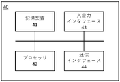
- FIG. 12 is a block diagram showing the configuration of an information processing apparatus according to a third embodiment of the present invention
- FIG. 12 It is a figure which shows the whole flow of the process of the 3rd Embodiment of this invention.
- the inventor of the present invention designed and analyzed various structures, and as a result, isolated the vibration mode in the vibration direction in which the vibration strength is to be increased from the vibration modes in the other directions, and in the vibration direction, While amplifying the vibration of the vibration source, with the idea of solving the above trade-off by giving the rigidity capable of supporting the assumed load, the structure according to the present invention and its design method devised.
- the concept of the present invention is to provide the structure with rigidity capable of supporting the expected load while amplifying the vibration of the vibrating body in the direction in which the vibration intensity is desired to be increased.
- the present invention is capable of amplifying the vibration of the vibration source by softening only the dynamic stiffness in the direction in which the vibration intensity is desired to be increased, and the static stiffness necessary to support the assumed load.
- a rigid structure is provided.
- T direction upward
- B direction downward
- F direction forward
- R direction backward
- SL direction leftward
- SR direction rightward directions
- rotation refers to rotation in one direction (clockwise or counterclockwise) as well as in both directions (clockwise and counterclockwise). can also mean an alternating rotation of .
- the structure of the first embodiment includes a vibration section, a housing, and a support section.
- the vibrating section holds the vibrating body.
- the housing at least partially houses the vibrating section.
- the support section supports the vibrating section by connecting the vibrating section and the housing. The vibrating portion holding the vibrating body vibrates in at least one direction.
- the support portion of the structure of the first embodiment is configured to have dynamic rigidity that amplifies vibration at least at a predetermined frequency among the vibrations generated by the vibrating portion holding the vibrating body.
- the supporting portion is configured to have at least the static rigidity necessary to support the vibrating portion holding the vibrating body.
- the support part secures sufficient rigidity (static rigidity) to stabilize the position and orientation of the vibrating part holding the vibrating body against the assumed load, and also the vibration generated by the vibrating part.
- the vibration intensity can be increased for at least a predetermined frequency of the vibration.
- dynamic stiffness means stiffness represented by the relationship between dynamic force or dynamic moment and resulting dynamic displacement
- static stiffness means static force or static It means the stiffness represented by the relationship between the static moment and the resulting static displacement/deformation.
- FIG. 1 shows a system including the structure of the first embodiment.
- FIG. 2 is a diagram showing another example of FIG.
- the supporting part SPT of the first embodiment supports the vibrating part OS by connecting the vibrating part OS holding the vibrating body and the housing HS.
- the vibrating part OS vibrates at a vibration frequency f.
- the vibrating part OS holding the vibrating body is depicted as if it vibrates due to linear reciprocating motion (hereinafter referred to as “linear reciprocating vibration”).
- linear reciprocating vibration can be oscillated in any direction.
- the vibration unit OS may vibrate by rotational motion (hereinafter referred to as “rotational vibration”) as shown in FIG. (hereinafter referred to as “swing vibration”).
- the vibration of the vibrating section OS may be any combination of the above vibration modes.
- FIG. 3 is a diagram showing a vibration model in the system of FIG.
- FIG. 4 is a graph showing frequency characteristics of the vibration transmissibility of the model of FIG.
- the support part SPT is configured to have a dynamic rigidity that amplifies the vibration at least at the vibration frequency f among the vibrations generated by the vibrating part OS while holding the vibrating body. 3 as a vibration transfer characteristic from the vibrating unit OS to the housing HS. It is determined by the dynamic stiffness kd of the support portion SPT with respect to the vibration direction of the portion OS.
- the ratio F/F0 of the excitation force F transmitted to the housing HS to the excitation force F0 generated by the vibrating part OS while holding the vibrating body is defined as the vibration transmission ratio.
- the model in FIG. 3 exhibits frequency characteristics in which the vibration transmissibility gradually decreases after an excited vibration mode in which the vibration transmissibility increases as the frequency increases.
- the vibration transmissibility of the model in FIG. 3 increases as the frequency becomes higher in the range below fu, and reaches a maximum at fu. where fu is the natural frequency of the model in FIG.
- the vibration transmissibility of the model in FIG. 3 gradually decreases in the frequency range equal to or higher than the natural frequency fu, and crosses zero at ⁇ 2fu. That is, in the model of FIG. 3, the vibration transmissibility is greater than 1 in the range of frequencies less than ⁇ 2fu, that is, the vibration strength can be amplified.
- the natural frequency of the model in Fig. 3 is determined by the mass m and the dynamic stiffness kd.
- the vibration transmissibility in the frequency range increases compared to the vibration transmissibility in the frequency characteristics of the system of the natural frequency fu indicated by the solid line in FIG. Since the mass m is a constant, the natural frequency fu can be lowered by reducing the dynamic stiffness kd. Therefore, from the viewpoint of improving the vibration transmissibility in the low-frequency range, it is preferable that the dynamic stiffness kd of the supporting portion SPT in the vibration direction of the vibrating portion OS holding the vibrating body is as small as possible.
- the support part SPT of the present embodiment is designed to generate vibration at least at a predetermined vibration frequency f, among the frequency components of vibration generated by the vibration part OS holding the vibrating body.
- the dynamic stiffness kd is determined so as to have a natural frequency fu at which the transmissibility is greater than one.
- a system including the supporting portion SPT and the vibrating portion OS having such a dynamic stiffness kd develops an excited vibration mode in which the vibration transmissibility is greater than 1 at the vibration frequency f.
- the support member SPT changes the natural frequency fu of the system including the support member SPT and vibration member OS to the vibration frequency f , and preferably matched to the vibration frequency f.
- the degree of the natural frequency fu of the system including the supporting portion SPT and the vibrating portion OS holding the vibrating body and how to determine the magnitude of the dynamic stiffness kd for that purpose depend on the vibration intensity. It can be appropriately determined according to how much amplification effect is desired at a predetermined vibration frequency f to be increased, that is, how high the vibration transmissibility is desired at the predetermined vibration frequency f.
- the dynamic stiffness kd of the support portion SPT can be derived, for example, by the following procedure.
- One end of the supporting portion SPT is connected to the housing HS, and the other end of the supporting portion SPT is connected to a weight having the same mass m as the vibrating portion OS holding the vibrating body.
- a natural vibration analysis is performed on the system of (1) to identify at least one set of natural frequencies and natural vibration modes.
- the support portion is provided with dynamic rigidity capable of exhibiting a vibration amplifying effect at a predetermined vibration frequency f at which the vibration intensity of the vibrating portion is to be increased, and the vibration direction of the vibrating portion is By increasing the amount of displacement (amplitude) of the supporting portion at , it is possible to increase the vibration intensity of the vibrating portion.
- the vibrating portion is supported in a suspended state with respect to the housing by the supporting portion, transmission of vibration by the vibrating portion to the housing is suppressed, and furthermore, the vibration is suppressed. is suppressed from propagating outside the structure.
- FIG. 5 shows an analysis model of the static stiffness of the supporting portion of the structure of the first embodiment.
- the support part SPT is configured to have static rigidity necessary to support the vibrating part OS while holding the vibrating body. Specifically, as shown in FIG. 5, the support part SPT has a static rigidity ks necessary to support the vibrating part OS against the design load Fl applied to the vibrating part OS.
- Supporting the vibrating part OS can mean, for example, stabilizing the position and orientation of the vibrating part OS even when the design load Fl is applied. Stabilizing the position and orientation can mean suppressing the displacement (including rotational displacement) due to the application of the design load Fl within an allowable range.
- the design load Fl is various loads assumed in the operating environment of the system including the vibrating portion OS and the supporting portion SPT holding the vibrating body.
- the design load Fl can include at least one of the following. Gravity (for example, the weight of the vibrating unit OS holding the vibrating body and the weight of the user acting on the vibrating unit OS) ⁇ inertial force
- the static stiffness ks required to support the vibrating portion OS against the design load Fl is, for example, the amount of displacement of the support portion SPT when the magnitude of the design load Fl is assumed to be the maximum value in the model of FIG. can be defined as the static stiffness that is within the design tolerance.
- the supporting portion SPT supports the vibrating portion OS by giving the supporting portion SPT the static rigidity ks necessary to support the vibrating portion OS in a state where the vibrating body is held against the design load Fl. configured to provide the static strength required for Specifically, when the magnitude of the design load Fl is assumed to be the assumed maximum value in the model of FIG. 5, the continuous distribution of the stress over the support portion SPT is obtained by analysis. Then, the maximum value of the stress distribution (that is, the maximum value of the stress assumed to be locally generated in the support portion SPT due to the design load Fl) is equal to or less than the allowable stress of the material constituting the support portion SPT. Determine SPT shape, location, material, or a combination thereof. Accordingly, even if the assumed maximum design load Fl is applied to the vibrating part OS, the supporting part SPT can stabilize the position and orientation of the vibrating part OS without being damaged.
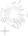
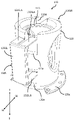
- FIG. 6 is a perspective view of the structure of the first embodiment as seen obliquely from above on the front side.
- FIG. 7 is a plan view showing the structure of the first embodiment with its upper flange portion cut away.
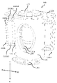
- 8 is a perspective view of the structure shown in FIG. 7 with the flange portion cut away, viewed from a direction different from that in FIG. 6.
- FIG. 9 is a perspective view showing a state in which the vibrating body is accommodated in the vibrating portion of the structure of the first embodiment.
- FIG. 10 is a perspective view showing an example of a structure having anisotropy in stiffness.
- the supporting part allows the vibrating part to be displaced along the first axis due to the vibration, while the vibrating part It is required to support the vibrating part so that it is not displaced in a direction different from the first axis due to gravity or vibration acting on itself or the vibrating body. Therefore, in such a structure, the dynamic rigidity in the vibration direction of the vibrating body is low enough to amplify the transmission of vibration, and the static rigidity is high enough to support the vibrating part in a stable position and orientation. High is desired.
- the structure 100 of this embodiment is based on the above idea.
- the supporting portion of the structure 100 supports the vibrating portion while holding the vibrating portion 140 (see FIG. 9) that vibrates in the vertical (TB) direction along the first axis. It is explained below.
- the displaceable direction of the vibrating portion 110 and the vibrating direction of the vibrating body held by the vibrating portion 110 are not limited thereto.
- the structure 100 includes a vibrating section 110 holding a vibrating body 140, a housing 120 housing the vibrating section 110, and a state in which the vibrating section 110 is suspended within the housing 120. It has two supporting parts 130SL and 130SR for supporting. The two support portions 130SL and 130SR are arranged differently, but have the same configuration. Therefore, items common to each supporting portion will be described using the reference numeral "130".
- the plane including the front-rear (FR) axis and the left-right (SR-SL) axis substantially coincides with the horizontal plane
- the up-down (TB) axis direction substantially coincides with the vertical direction.
- the vibrating portion 110 has a hollow, substantially cylindrical shape with a bottom portion 110b and an upper opening in the drawing, and a vibrating body 140 is accommodated in the hollow portion of the cylindrical interior as shown in FIG. .
- the vibrating body 140 is fixed to the bottom portion 110b by screwing through a screw hole formed in the bottom portion 110b, for example.
- the inner diameter of the vibrating portion 110 is preferably substantially the same as the outer diameter of the substantially cylindrical vibrating body 140 housed therein. The vibrating portion 110 holding the vibrating body 140 inside in this way can be displaced integrally with the vibrating body 140 .
- the vibrating body 140 is, for example, a linear motor such as a voice coil motor, and the vibrating body 140 held by the vibrating portion 110 linearly reciprocates along the illustrated vertical (TB) axis.
- the vibrating portion 110 linearly reciprocates along the vertical (TB) axis in the drawing in accordance with the vibration generated by the vibrating body 140 .
- Openings 110a are formed at two opposing locations on the side surface of the vibrating portion 110 . These openings 110a allow an operator to reach for attaching or detaching the vibrating body 140 in the vibrating part 110, and also dissipate the heat generated by the vibrating body 140 when the vibrating body 140 is driven. It has a role of dissipating heat to the outside of the vibrating section 110 .
- the housing 120 is configured in a substantially cylindrical shape with at least an upper opening in the drawing, and the whole or at least part of the vibrating section 110 is accommodated in a cylindrical hollow portion around the central axis of the housing 120 .
- the housing 120 accommodates the vibrating section 110 so as to surround the vibrating section 110 entirely.
- Openings 120a are formed at two opposing locations on the side surface of the housing 120 and at positions overlapping the respective openings 110a formed on the side surface of the vibrating unit 110 housed inside. These openings 120a are also accessible to the operator for attaching or detaching the vibrating body 140 to or from the vibrating part 110, and heat generated by the vibrating body 140 when the vibrating body 140 is driven can be dissipated. It has a role of dissipating heat to the outside of the housing 120 .
- a flange portion 120b is formed around the opening in the upper portion of the housing 120 in the figure. In this example, as an example, the flange portion 120b has a shape extending in the horizontal direction of the housing 120 in the drawing. The flange portion 120b plays a role of supporting the load when the user sits or leans on the illustrated upper portion of the housing 120 .
- a mounting flange portion 120c having screw holes is formed around the outer periphery of the lower portion of the housing 120 in the figure.
- mounting flange portions 120c are formed at two locations on the front side and rear side of the housing 120 in the figure.
- the structure 100 can be fixed to the object (not shown) to which the structure 100 is to be attached by, for example, screwing through the screw holes of the mounting flange portion 120c.
- cutouts 120d and 120e are formed in the upper and lower regions of the left and right side surfaces of the housing 120, respectively. These notch portions 120d and 120e allow a support member 132 fixed to the side surface of the vibrating portion 110 among the support portions 130 described later to extend outside the housing 120 through the side wall of the housing 120. and prevent the support 132 from contacting the sidewalls of the housing 120 when the support 132 is displaced.
- the support portion 130 supports the vibrating portion 110 in a suspended state within the housing 120 so that the vibrating portion 110 linearly reciprocates along the first axis (vertical (TB) direction in the illustrated example).
- the vibrating section 110 is concentric with the central axis of the housing 120 in the inner space of the housing 120, and a gap is generated between the outer peripheral surface of the vibrating section 110 and the inner peripheral surface of the housing 120.
- the vibration unit 110 is set at a height such that the bottom surface of the vibration unit 110 does not come into contact with the bottom surface of the housing 120 or the object to which the structure 100 is attached even when the vibration unit 110 is displaced by the maximum amount of displacement that is assumed when vibrating in the vertical direction. position.
- the vibrating section 110 is supported by the supporting section 130 at such an arrangement position.
- a support 132SLA as a first support and a support 131SLA as a second support whose one end (first end) is fixed to the housing 120 and the lower side of the structure 100 shown in the figure vibrate.
- a support 132SLB as a first support having one end (first end) fixed to the portion 110 and a second support having one end (first end) fixed to the housing 120 It includes a support 131SLB as a body and a connecting portion 133SL to which the other ends (second ends) of the supports 131SLA, 132SLA, 131SLB and 132SLB are fixed.
- Support 131SLA and support 132SLA on the upper side in the figure constitute a first set
- support 131SLB and support 132SLB on the lower side in the figure constitute a second set
- the other end portions of the first set of supports 131SLA and 132SLA are fixed to the connection portion 133SL near the illustrated upper end portion of the connection portion 133SL
- the other ends of the second set of supports 131SLB and 132SLB are fixed.
- the end portion is fixed to the connecting portion 133SL in the vicinity of the illustrated lower end portion of the connecting portion 133SL. Therefore, the first set of supports 131SLA and 132SLA and the second set of supports 131SLB and 132SLB are spaced apart from each other along the vertical (TB) axial direction in the figure.
- support 132SLA one end of which is fixed to vibrating section 110 is illustrated left and right (SL-SR).
- the length in the direction is longer than the length in the same direction of the 131SLA, one end of which is fixed to the housing 120 .
- the length in the left-right (SL-SR) direction of the supporting body 132SLB attached is longer than the length in the same direction of 131SLB, one end of which is fixed to the housing 120 .
- the supporting section 130SL configured in this manner allows the relative position of the vibrating section 110 with respect to the housing 120 to be displaced along the vertical (TB) axis by elastic deformation of the respective supporting bodies 131SLA, 132SLA, 131SLB, and 132SLB. It supports the vibrating section 110 .
- the other support portion 130SR also has the same configuration as the support portion 130SL.
- These two support parts 130SL and 130SR are arranged so as to face each other symmetrically about the central axis of the structure 100 (which is also the concentric central axis of the vibrating part 110 and the housing 120).
- FIGS. 6 to 9 show a state in which the vibrating section 110 is positioned at a neutral position with respect to the housing 120 when no vibrating force is acting on the vibrating section 110 .
- an excitation force acting upward in the figure (T direction) acts on the vibrating part 110, and when the vibrating part 110 is displaced upward in the figure with respect to the housing 120, the support fixed to the vibrating part 110 is displaced.
- One end of the body 132SLA and the support 132SLB is also displaced upward in the figure accordingly.
- the support 132SLA and the support 132SLB have one end fixed to the vibrating portion 110 and the other end fixed to the connecting portion 133SL as restraint ends. It is displaced upward in the figure while being bent and deformed within the elastic deformation region so that the end portion fixed to 110 faces the upper side in the figure.
- the connecting portion 133SL to which the other ends of the support 132SLA and the support 132SLB are fixed is also somewhat displaced upward in the drawing.
- the supporting body 131SLB also has one end fixed to the connecting part 133SL and one end fixed to the housing 120 as restraint ends, and the end fixed to the connecting part 133SL is illustrated. It is displaced upward in the figure while being bent and deformed in the elastic deformation region so as to face upward.
- each part of the part 133SL is displaced or deformed in the direction opposite to the above. Although description is omitted, each part of the other support part 130SR also operates in the same manner as each part of the support part 130SL.
- the vibrating portion 110 supported by the supporting portions 130SL and 130SR linearly vibrates reciprocatingly in the vertical (TB) direction in the figure by the vibrating force of the vibrating body 140 as described above.
- the support section 130 is vibrated with respect to the housing 120 by elastic deformation of the illustrated upper and lower supports 132SLA and 132SLB as first supports and the illustrated upper and lower supports 131SLA and 131SLB as second supports. support the vibrating portion 110 so as to be displaceable along the first axis (vertical (TB) axis direction in the drawing).
- the weight of the vibrating body 140 makes the vibrating part 110 slightly larger than when the vibrating body 140 is not housed in the vibrating part 110. Displaced downward in the drawing. Furthermore, when the vibrating body 140 is accommodated in the vibrating section 110 , the illustrated upper portion of the vibrating body 140 slightly protrudes outside the housing 120 from the upper surface of the flange portion 120 b of the upper portion of the housing 120 . Therefore, when the user sits or leans against the illustrated upper portion of the housing 120, the illustrated upper surface of the vibrating body 140 vibrates until it reaches substantially the same height as the upper surface of the upper flange portion 120b of the housing 120.
- the portion 110 is further pushed downward in the drawing, and the vibrating portion 110 is held by the support portions 130SL and 130SR with that position as the neutral position. At this time, the load of the user's body is supported by the flange portion 120b of the housing 120, and the upper upper surface of the vibrating body 140 pushed down together with the vibrating portion 110 comes into contact with the user's body.
- the support portion 130 is configured to generate at least a predetermined vibration frequency among the linear reciprocating vibrations generated along the vertical (TB) axis by the vibrating portion 110 holding the vibrating body 140, in other words, the predetermined vibration. It is configured to have a dynamic stiffness that amplifies vibrations in a frequency band that includes frequencies.
- the dynamic rigidity of the support section 130 is a load that is assumed to be applied to the support section 130 via the vibration section 110 (for example, a load due to the weight of the vibration section 110 holding the vibration body 140 or a load applied to the structure 100). It can be determined in consideration of the load acting on the vibrating section 110 from the body of the user sitting or leaning.
- the vibrating section 110 can generate vibrations of different frequencies according to the speed of the linear reciprocating vibration generated by the vibrating body 140 .
- the support portion 130 makes it possible to amplify vibration in a frequency band including a predetermined frequency for which higher vibration intensity is desired to be achieved.
- the support portion 130 is configured to have static rigidity necessary to support the vibrating portion 110 . That is, the support portion 130 ensures sufficient rigidity (static rigidity) to stabilize the position and orientation of the vibrating portion 110 against an assumed load, and at least the linear reciprocating vibration generated by the vibrating portion 110 A high vibration intensity can be realized with respect to the predetermined vibration frequency.
- the support portion 130 resists the force applied along the vibration direction of the vibrating portion 110 holding the vibrating body 140 (that is, the force applied along the vertical (TB) axis). It is designed to have low dynamic stiffness and static stiffness against the design load.
- the support part 130 can satisfy both the constraint on dynamic stiffness and the constraint on static stiffness by including, for example, a structure having anisotropy in terms of stiffness.
- the support portion 130 has a rigidity against a force applied along a direction different from the rigidity against a force applied along the vibration direction of the vibrating portion 110 holding the vibrating body 140 . is configured to be high.
- Stiffness against force applied along another direction is, for example, all or at least one of the following: ⁇ Stiffness against moment around vertical (TB) axis ⁇ Stiffness against force applied along front-back (FR) axis ⁇ Stiffness against moment around front-back (FR) axis ⁇ Side-left (SL-SR) Stiffness against force applied along the axis / Stiffness against moment around the left-right (SL-SR) axis
- the beam BM shown in FIG. 10 is an example of a structure having anisotropy in terms of rigidity, and corresponds to each support 131SLA, 132SLA, 131SLB, 132SLB in this embodiment.
- the beam BM is such that the dimension a in the vibration direction (that is, the vertical (TB) axis) of the vibrating portion 110 holding the vibrating body 140 is equal to the dimension b of the front-rear (FR) axis and the lateral axis (SL- SR) is small compared to the axis dimension l.
- the stiffness when a force is applied along the vertical (TB) axis to the right end (SR end) of the beam BM while the left end (SL end) of the beam BM is fixed is K b1 ⁇ Ea 3 b/l 3 expressed.
- E Young's modulus.
- the stiffness is K b2 ⁇ Eab 3 /l 3 is. That is, K b2 /K b1 ⁇ b 2 /a 2 .
- the vertical (TB) axis By making the dimension a of the vertical (TB) axis smaller than the dimension b of the front-rear (FR) axis and the dimension l of the lateral axis (SL-SR axis), the vertical (TB) ) the stiffness for forces applied along the axis can be lower than the stiffness for forces applied along other directions.
- Structures with undulating shapes in the vertical (TB) direction also have a stiffness to forces applied along the vertical (TB) axis that is equal to the stiffness to forces applied along the other directions. low compared to
- each support for example, the support 131SLA, the support 131SLB, the support 132SLA, and the support 132SLB
- the support section 130 is moved in the direction along the first axis (that is, the vertical (TB) direction) is smaller than the dimension in the direction perpendicular to the first axis (the front-rear (FR) direction or the left-right (SL-SR) direction).
- the dynamic stiffness in the direction along the first axis of can be reduced.
- the supports 131 and 132 of each support 130 are configured to have the above-described rigidity characteristics, and the two supports 130SL and 130SR are the central axes of the structure 100 (the vibrating section 110 and the housing). ), which is also the concentric center axis of the body 120), the vibrating section 110 can be displaced in the vertical (TB) direction in the drawing with respect to the housing 120. is supported by the support portion 130 so as not to be substantially displaced in other directions.
- each of the supports 131SLA, 132SLA, 131SLB, and 132SLB of the support section 130 has a relatively low dynamic rigidity in the vertical (TB) direction of the drawing as described above.
- the load due to the weight of the vibrating section 110 supporting the vibrating body 140, and the vibration when the vibrating section 110 supporting the vibrating body 140 as described above is pushed downward (B) in the figure by the user's body. It has static stiffness capable of supporting at least the loads applied to the portion 110 .
- the connecting portion (for example, connecting portion 133SL) included in the support portion 130 is separated from the housing 120 in a direction orthogonal to the vibration direction (that is, the vertical (TB) direction) of the vibrating portion 110 holding the vibrating body 140.
- TB vertical
- each support (for example, support 131SLA, support 131SLB, support 132SLA, and support 132SLB) included in the support section 130 looks like a housing when viewed from above (T direction). It extends radially outward from the outer peripheral surface of 120 .
- the vertical (TB) relative to the dimension along the vertical (TB) axis of each support increases. Since the dimension ratio in the direction perpendicular to the axis (left-right (SL-SR) direction) increases, the dynamic rigidity of the support portion 130 in the vibration direction (up-down (TB) direction in the figure) can be made lower.
- the dimensions of each part, including the length of each support are determined in consideration of the size of the structure 100 and the weight of the vibrating body 140, etc. can be appropriately set so that the can be amplified.
- the support portion 130 When the vibrating section 110 holding the vibrating body 140 is in a non-vibrating state, no vibrating force is applied to the support section 130 .
- the support portion 130 is subjected to the above-described load (for example, the weight of the vibrating portion 110 holding the vibrating body 140, or the weight of the structure 100).
- a load acting on the vibrating section 110 by the body of the user sitting or leaning can be applied.
- the supporting portion 130 has static rigidity such that the amount of displacement of the supporting portion 130 is within a design allowable range with respect to the direction in which the design load is applied. Therefore, when the vibrating portion 110 is in the non-vibrating state, the deformation of each support of the support portion 130 remains within the allowable range, and the support portion 130 is in the neutral position after being displaced by the application of the load. To position.
- the supporting part 130 is also subjected to a load along the upward direction in the drawing (T direction). A vibration force is applied.
- the vibrating portion 110 holding the vibrating body 140 is displaced downward in the drawing (direction B)
- an excitation force along the downward direction in the drawing is also applied to the supporting portion 130 .
- the support part 130 has a dynamic rigidity that amplifies at least the vibration of the predetermined frequency among the linear reciprocating vibrations in the vertical (TB) direction in the figure generated by the vibrating part 110 holding the vibrating body 140. It is configured. As a result, at least at the predetermined vibration frequency of the vibrating portion 110, the vibration intensity of the linear reciprocating vibration of the vibrating portion 110 in the vertical (TB) direction in the drawing can be increased.
- the vibrating device configured by the structure 100 of the present embodiment in which the vibrating body 140 is held by the vibrating part 110, the upper surface of the vibrating body 140 is in contact with the user's body.
- the vibrating body 140 is linearly reciprocated in the vertical (TB) direction in the figure, the vibrating part 110 holding it starts reciprocating linear vibration in the same direction, and eventually the vibration frequency reaches the predetermined frequency.
- the to-and-fro linear vibration in the -B) direction is amplified.
- the upper upper surface of the vibrating body 140 held by the vibrating section 110 is displaced in the (T) direction in the drawing, the upper upper surface of the vibrating body 140 contacts the user's body more strongly. In the frequency domain, the acoustic effect of the vibrating device can be felt more strongly. At this time, the user will feel the vibration of the body in addition to the sound and image of the audio/visual content (movie, music live video, etc.) being viewed, so that the user can get a stronger sense of immersion in the content. can be done.
- the vibrating section 110 is supported in a suspended state by the support section 130 so as not to contact the inner wall surface, bottom surface, or the like of the housing 120.
- This suspended state is maintained even while the vibrating portion 110 reciprocating linearly vibrates in the vertical (TB) direction of the drawing.
- the vibration caused by the vibrating section 110 is separated from the housing 120 .
- the vibrating section 110 linearly vibrates back and forth in the illustrated vertical (TB) direction the vibrating section 110 and the vibrating body 140 held by it may come into contact with the inner wall surface, the bottom surface, or the like of the housing 120.
- vibration transmitted from the housing 120 to the outside thereof can be suppressed.
- the vibration from one vibrating device is transmitted to another vibrating device and interferes with the vibration of the other vibrating device. It can be suppressed, and the user can perceive the vibration by the individual vibrating device with higher resolution.
- the vibrating device including the structure 100 and the vibrating body 140 of the present embodiment can displace the vibrating part 110 supported by the supporting part 130 in the reciprocating linear vibration direction of the vibrating part 140 held by the vibrating part 110 .
- direction coincides with the vertical (TB) direction in the drawing, and the vibrating portion 110 is not substantially displaced in other directions. Therefore, most of the vibrational energy of the vibrating body 140 is used to linearly vibrate the vibrating portion 110 back and forth in the vertical (TB) direction in the drawing.
- the vibrating section 110 is linearly reciprocated in the vertical (TB) direction of the drawing, the vibrating section 110 sequentially generates secondary, tertiary, .
- the vibrating portion 110 may vibrate in directions other than the illustrated vertical (TB) direction.
- the vibrating section 110 is configured so that there is substantially no displacement in directions other than the illustrated vertical (TB) direction. 110 can be suppressed from being displaced in the vibration direction. Therefore, even if the vibrating section 110 vibrates in a certain vibration mode in a direction other than the illustrated vertical (TB) direction, the outer peripheral surface of the vibrating section 110 may contact the inner peripheral surface of the housing 120, for example. can be prevented.
- the support member 131SLA of the support portion 130 in order to increase the vibration intensity of the reciprocating linear vibration of the vibrating portion 110 in the vertical (TB) direction of the drawing at a lower frequency, the support member 131SLA of the support portion 130, The shape and dimensions of each support are designed so that the dynamic stiffness kd in the vertical (TB) direction of the drawing by the entirety of 132SLA, 131SLB, and 132SLB is lower.
- the natural frequency fu of the vibration of the system composed of the vibrating portion 110 holding the vibrating body 140 and the supporting portion 130 in the vertical (TB) direction in the drawing shifts to a lower frequency region, It becomes possible to increase the vibration intensity in the frequency domain.
- the illustrated vertical (T-) direction of the vibrating section 110 when increasing the vibration intensity of the reciprocating linear vibration in the illustrated vertical (TB) direction of the vibrating section 110 at a higher frequency, the illustrated vertical (T- The shape and dimensions of each support are designed so that the dynamic stiffness kd in the B) direction is higher. As a result, the natural frequency fu of the vibration in the vertical (TB) direction in the drawing of the system composed of the vibrating portion 110 holding the vibrating body 140 and the support portion 130 shifts to a higher frequency region, It becomes possible to increase the vibration intensity in the frequency domain.
- the structure 100 of the first embodiment includes the support section 130 .
- the supporting section 130 performs vibration of at least a predetermined vibration frequency (vibration in a frequency band including the predetermined vibration frequency).
- the predetermined vibration frequency is, for example, a frequency at which it is desired to amplify the vibration of the vibrating section 110 to obtain a higher vibration strength.
- the support section 130 is configured to have static rigidity necessary to support the vibrating section 110 against an assumed load in the direction in which the designed external force is applied.
- the vibrating portion 110 is supported so that the position and orientation of the vibrating portion 110 are stabilized against the load within the assumed range at the time of design, and at least the linear reciprocating vibration generated by the vibrating portion 110
- the vibration of the predetermined frequency can be amplified.
- this structure 100 it is possible to satisfy the load resistance and vibration strength required of a vibrating device.
- the direction in which the vibrating section 110 can be displaced (vibrated) matches the vibrating direction of the vibrating body 140 held by the vibrating section 110, and the vibrating section 110 is positioned relative to the housing 120. Since it is internally supported by the support portion 130 in a suspended state, it is possible to suppress the occurrence of vibration in the direction of vibration by the vibrating portion 110 and vibration in a direction different from that, and such vibration can be suppressed. can be suppressed from propagating to the outside of the structure 100 .
- the vibrating section 110 holding the vibrating body 140 generates a linear reciprocating vibration along a vertical (TB) axis in the figure, which substantially coincides with the vertical direction.
- TB vertical
- the weight of vibrating section 110 holding 140, the excitation force (inertial force) thereof, and the load from the user's body are applied to vibrating section 110 .
- the support portion 130 is configured to have dynamic rigidity that amplifies at least the vibration of the vibration portion 110 at the predetermined vibration frequency in the vertical (TB) direction, which is the vibration direction of the vibration portion 110.
- the static rigidity required to support the vibrating portion 110 is provided.
- the vibration direction of the vibrating portion 110 supported by the support portion 130 and the direction in which the design external force is applied to the support portion 130 are not limited to this. Moreover, the vibration direction of the vibrating portion 110 supported by the support portion 130 is not limited to one direction.
- the support portion 130 may be configured to have a dynamic stiffness that amplifies vibration at a predetermined vibration frequency in each vibration direction.
- the structure 100 includes two supporting portions 130SL and 130SR arranged symmetrically to face each other with respect to its central axis. is not limited to this, and may be configured to include any number of support portions 130, for example, three or more. At this time, it is preferable that the support portions 130 are arranged at regular intervals around the central axis of the structure 100 . Note that even when the structure 100 includes only one support portion 130, the vibrating body 140 and the vibrating portion 110 come into contact with the inner surface of the housing 120 when the vibrating portion 110 holding the vibrating body 140 vibrates.
- the structure 100 may be configured with only one support 130 under certain conditions where there is no need to do so.
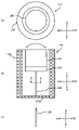
- FIG. 11A and 11B are diagrams showing the structure of the second example of the first embodiment of the present invention, FIG. 11A is a plan view thereof, and FIG. , and FIG. 1(c) is a cross-sectional view of the supporting portion taken along the line AA.
- the structure 200 includes a vibrating portion 210 holding a vibrating body 240, a supporting portion 230 supporting the vibrating portion 210, and a vibrating portion holding the vibrating body 240. 210 and a housing 220 that accommodates the support 230 .
- the vibrating portion 210 has a disk-like shape as an example, and the vibrating body 240 can be held on the upper surface of the drawing.
- the vibrating body 240 can be fixed to the vibrating portion 210 by screwing (not shown), for example.
- the vibrating portion 210 holding the vibrating body 240 can be displaced integrally with the vibrating body 240 .
- the vibrating portion 210 is supported by the support portion 230 in a state in which the lower surface in the figure is fixed to the upper portion in the figure of the support portion 230 .
- the vibrating body 240 has, for example, a substantially cylindrical shape having the same outer diameter as the vibrating portion 210, the shape of the vibrating body 240 is not limited to this.
- the support portion 230 has a cross-shaped cross section along line AA in FIG. 11(b) as shown in FIG. 11(c). ) along the axis. More specifically, the support portion 230 is formed in a shape in which two plate-like members are perpendicular to each other at their central axes. The illustrated upper portion of the support portion 230 is fixed to the vibrating portion 210 as described above, and the illustrated lower portion of the support portion 230 is fixed to the bottom surface 220 a of the housing 220 .
- the housing 220 is configured in a substantially cylindrical shape with an upper opening in the drawing. contain at least part of In the example shown in FIG. 11 and the like, the housing 220 accommodates the vibrating section 210 holding the vibrating body 240 and the supporting section 230 so as to surround the entire circumference thereof.
- the vibrating portion 210 and the support portion 230 holding the vibrating body 240 are concentric with the central axis of the housing 220 in the inner space of the housing 220 and between the outer peripheral surface thereof and the inner peripheral surface of the housing 220. are arranged so that there is a gap between them.
- a flange may be formed around the opening at the top of the housing 220 as shown.
- the vibrating body 240 is, for example, a rotating vibrator capable of rotating and vibrating alternately clockwise and counterclockwise. As indicated by the arrow in (a), the vibrating portion 210 rotates and vibrates alternately clockwise and counterclockwise, and the vibrating portion 210 also rotates and vibrates in the same direction integrally with the vibrating body 240 .
- the upper upper surface of the vibrating body 240 held by the vibrating section 210 is substantially at the same height as the opening surface of the upper portion of the housing 220 in the drawing. Therefore, when the user sits or leans against the illustrated upper portion of the housing 220, the illustrated upper upper surface of the vibrating body 240 may come into contact with the user's body.
- the support portion 230 is configured to generate vibration of at least a predetermined vibration frequency (a frequency band including the predetermined vibration frequency) among the rotational vibrations generated by the vibration portion 210 holding the vibration body 240 about the vertical (TB) axis in the drawing. (vibration at the ).
- the dynamic rigidity of the support section 230 is a load that is assumed to be applied to the support section 230 via the vibration section 210 (for example, a load due to the weight of the vibration section 210 holding the vibration body 240 or a load applied to the structure 200). It can be determined in consideration of the load acting on the vibrating section 210 via the vibrating body 240 due to the body of the user sitting or leaning.
- the vibrating section 210 can generate vibrations of different frequencies according to the rotational vibration speed generated by the vibrating body 240 .
- the support portion 230 makes it possible to amplify vibration in a frequency band including a predetermined frequency for achieving higher vibration strength among those frequencies.
- the support portion 230 is configured to have static rigidity necessary to support the vibrating portion 210 .
- the support portion 230 secures sufficient rigidity (static rigidity) to stabilize the position and orientation of the vibrating portion 210 against an assumed load, and at least the above-described rotational vibration generated by the vibrating portion 210 is ensured.
- a high vibration intensity can be achieved for a given vibration frequency.
- the support portion 230 in this embodiment applies a force along the vibration direction of the vibrating portion 210 holding the vibrating body 240 (that is, a force applied around the vertical (TB) axis in the drawing). It is configured so that it has low dynamic stiffness against the force applied to it, but static stiffness against the design load is obtained.
- the support part 230 can satisfy both the dynamic stiffness constraint and the static stiffness constraint by including, for example, a structure having anisotropic stiffness.
- the support part 230 has the following characteristics due to its geometric shape having a cross section. ⁇ The dynamic rigidity against the rotational moment around the vertical (TB) axis in the figure is low, and torsional deformation in that direction is likely to occur. ⁇ High static rigidity against compression and tension in the vertical (TB) axial direction in the drawing, and substantial deformation in that direction is unlikely to occur. ⁇ High static rigidity against a bending moment in a direction orthogonal to the illustrated vertical (TB) axis direction, and substantial bending deformation in that direction is unlikely to occur.
- each part (height, length and thickness of the cross section, etc.) of the support part 230 are determined in consideration of the size of the structure 200, the weight of the vibrating body 240, etc. It can be appropriately set so that the vibration of 210 can be amplified.
- the supporting part 230 When the user sits or leans against the illustrated upper portion of the structure 200 of the present embodiment in which the vibrating body 240 is held by the vibrating part 210, the supporting part 230 is applied with a design load (for example, the vibrating body 240 is held). A load acting on the vibration part 210 due to the weight of the vibration part 210 when the user sits or leans against the structure 200 may be applied to the vibration part 210 .
- the supporting portion 230 is configured as described above with respect to the application direction of such a design load (the illustrated vertical (TB) axis direction and the direction perpendicular thereto (the illustrated vertical (TB) axis direction)). It has high static stiffness. Therefore, the support portion 230 can support such a designed load, and substantially no displacement due to such a designed load occurs.
- the supporting part 230 When the vibrating body 240 held by the vibrating part 210 enters a vibrating state and the vibrating part 210 holding the vibrating body 240 rotates in one direction around the illustrated vertical (TB) axis, the supporting part 230 also vibrates in the same direction. An excitation force is applied in the direction. On the other hand, when the vibrating portion 210 holding the vibrating body 240 rotates in the other direction around the illustrated vertical (TB) axis, the excitation force is applied to the supporting portion 230 in the same other direction as well.
- the support part 230 has a dynamic rigidity that amplifies at least the vibration of the predetermined frequency among the rotational vibrations about the vertical (TB) axis in the figure generated by the vibration part 210 holding the vibration body 240. It is configured. Thereby, at least at the predetermined vibration frequency of the vibrating portion 210, the vibration intensity of the rotational vibration of the vibrating portion 210 about the vertical (TB) axis in the figure can be increased.
- the vibrating device configured by the structure 200 of the present embodiment in which the vibrating body 240 is held by the vibrating part 210, the upper surface of the vibrating body 240 is in contact with the user's body.
- the vibrating body 240 is rotationally vibrated around the vertical (TB) axis in the figure, the vibrating part 210 holding it starts to rotationally vibrate in the same direction, and when the vibration frequency eventually reaches the predetermined frequency,
- the system including the vibration part 210 holding the vibration body 240 and the support part 230 resonates with the natural frequency of the vibration about the vertical (TB) axis in the drawing, and the vibration part 210 holding the vibration body 240 resonates at the vertical (T -B) Rotational oscillations about the axis are amplified.
- the vibrating body 240 held by the vibrating part 210 is rotationally displaced, the user's body part with which the upper surface of the vibrating body 240 is in contact is stimulated by alternately twisting clockwise and counterclockwise. is given to the user, the user can feel the acoustic effect of the vibrating device more strongly in the frequency range. At this time, the user will feel the vibration of the body in addition to the sound and image of the audio/visual content (movie, music live video, etc.) being viewed, so that the user can get a stronger sense of immersion in the content. can be done.
- the vibrating device including the structure 200 and the vibrating body 240 of the present embodiment is configured so that the vibration direction of the rotational vibration of the vibrating body 240 held by the vibrating section 210 and the displacement of the vibrating section 210 supported by the supporting section 230 are controlled.
- the direction of rotation coincides with the direction of rotation about the vertical (TB) axis in the drawing, and the vibrating portion 210 is not substantially displaced in other directions. Therefore, most of the vibrational energy of the vibrating body 240 is used to rotationally vibrate the vibrating section 210 about the vertical (TB) axis in the drawing.
- the vibrating portion 210 is rotationally vibrated around the vertical (TB) axis in the drawing, secondary, tertiary, .
- the vibrating section 210 may vibrate in directions other than the direction of rotation about the illustrated vertical (TB) axis. 200 is configured so that the vibrating portion 210 is substantially not displaced in directions other than the rotation direction about the illustrated vertical (TB) axis. It is possible to suppress displacement of the vibrating portion 210 in the direction of vibration caused by vibrations that may occur in directions other than the direction of rotation. Therefore, even if the vibrating section 210 vibrates in a certain vibration mode in a direction other than the direction of rotation about the vertical (TB) axis in the drawing, for example, the outer peripheral surfaces of the vibrating section 210 and the vibrating body 240 held by the vibrating section 210 may Contact with the inner peripheral surface of the body 220 can be prevented.
- the vibrating portion 210 is prevented from being displaced in a direction other than the direction of rotation about the vertical (TB) axis in the figure due to vibrations that may occur in the directions other than the direction of rotation. Therefore, it is possible to prevent the vibrating device from vibrating due to displacement in a direction other than the rotational direction about the illustrated vertical (TB) axis, and the vibration from propagating to the outside of the vibrating device. .
- the vibration from one vibrating device is transmitted to another vibrating device and interferes with the vibration of the other vibrating device. It can be suppressed, and the user can perceive the vibration by the individual vibrating device with higher resolution.
- FIG. 12A and 12B are views showing the structure of the third example of the first embodiment of the present invention
- FIG. 12A is a plan view thereof
- FIG. 1(c) is a cross-sectional view of the supporting portion taken along the line BB.
- a structure 250 according to the third embodiment includes a vibrating portion 260 that holds a vibrating body 290 and a vibrating portion 260, similar to the structure 200 according to the second embodiment (see FIG. 260 , and a housing 270 that houses the vibrating section 260 and the supporting section 280 while holding the vibrating body 290 .
- the vibrating body 290 used in this embodiment is, for example, a vibrating body capable of linear reciprocating vibration, and as an example thereof, a linear motor such as a voice coil motor can be used.
- the vibrating body 290 is held by the supporting portion 280 so that the direction of the linear reciprocating vibration coincides with the horizontal (SL-SR) direction in the drawing.
- the vibrating body 290 may be a rotary vibrator capable of rotating and oscillating alternately clockwise and counterclockwise, like the vibrating body 240 of the second embodiment.
- the vibrating body 290 is held by the supporting portion 280 so that its central axis of rotation is orthogonal to the horizontal (SL-SR) direction in the figure.
- the support portion 280 in the structure 250 of the present embodiment has a plate-like shape whose cross section along line BB in FIG. have.
- the illustrated upper portion of the support portion 280 is fixed to the vibrating portion 260 as described above, and the illustrated lower portion of the support portion 280 is fixed to the bottom surface 270 a of the housing 270 .
- the support portion 280 supports at least vibration of a predetermined vibration frequency (vibration in a frequency band including the predetermined vibration frequency) among the vibrations generated in the horizontal (SL-SR) direction in the figure by the vibration portion 260 holding the vibrator 290. ) is configured to have a dynamic stiffness that amplifies the
- the dynamic rigidity of the support section 280 is determined by the load that is assumed to be applied to the support section 280 via the vibration section 260 (for example, the load due to the weight of the vibration section 260 holding the vibration body 290 and the load applied to the structure 250). It can be determined in consideration of the load acting on the vibrating section 260 via the vibrating body 290 due to the body of the user sitting or leaning.
- the vibrating section 260 can generate vibrations of different frequencies according to the speed of vibration generated by the vibrating body 290 .
- the support portion 280 makes it possible to amplify vibration in a frequency band including a predetermined frequency for achieving higher vibration strength among those frequencies.
- the support portion 280 is configured to have static rigidity necessary to support the vibrating portion 260 . That is, the support portion 280 ensures sufficient rigidity (static rigidity) to stabilize the position and orientation of the vibrating portion 260 against an assumed load, and at least the above-mentioned predetermined amount of vibration generated by the vibrating portion 260 A high vibration intensity can be realized with respect to the vibration frequency of
- the support portion 280 in this embodiment applies a force along the vibration direction of the vibrating portion 260 holding the vibrating body 290 (when the vibrating body 290 is a vibrating body capable of linear reciprocating vibration).
- It is configured to provide static stiffness against load.
- the support part 280 can satisfy both the constraint on dynamic stiffness and the constraint on static stiffness, for example, by including a structure having anisotropy in terms of stiffness.
- the support part 280 has the following characteristics due to its planar geometry. ⁇ The dynamic rigidity against the bending moment in the illustrated left-right (SL-SR) direction and about the illustrated front-rear (FR) axis is low, and bending deformation in that direction is likely to occur. ⁇ High static rigidity against compression and tension in the vertical (TB) axial direction in the drawing, and substantial deformation in that direction is unlikely to occur. ⁇ High static rigidity against a bending moment in a direction perpendicular to the illustrated left-right (SL-SR) direction (the illustrated front-rear (FR) direction), and substantial bending deformation in that direction is unlikely to occur.
- the support portion 280 When the vibrating body 290 is a vibrating body capable of linear reciprocating vibration, as described above, the support portion 280 has low dynamic rigidity against a bending moment in the left and right (SL-SR) directions of the drawing, and bending deformation in that direction occurs.
- the vibrating body 290 since the vibrating body 290 is held by the supporting portion 280 so that the direction of linear reciprocating vibration is aligned with the horizontal (SL-SR) direction in the figure, the vibrating body 290 generates linear reciprocating vibration.
- the support portion 280 alternately bends in the left and right (SL-SR) directions in the drawing with the lower end portion fixed to the bottom surface 270a of the housing 270 as a fixed end and the upper end portion fixed to the vibration portion 260 as a free end.
- the supporting portion 280 and the vibrating body 290 held by it alternately oscillate in the left and right (SL-SR) directions as indicated by the arrows in FIG. 12(b).
- the support part 280 When the vibrator 290 is a rotary vibrator capable of rotating and vibrating alternately clockwise and counterclockwise, the support part 280 has dynamic rigidity against a bending moment about the longitudinal (FR) axis in the figure, as described above. is low, and bending deformation in that direction is likely to occur. Since it is held by the support portion 280 , when the vibrating body 290 causes rotational vibration, the support portion 280 uses the lower end portion fixed to the bottom surface 270 a of the housing 270 as a fixed end and the upper end portion fixed to the vibrating portion 260 .
- the bending moment due to the rotational vibration of the vibrating body 290 applied to the upper end surface causes the bending moment to undulate in the left and right (SL-SR) directions of the drawing, thereby forming the supporting portion 280 and the supporting portion 280 held by it.
- the vibrating body 290 oscillates alternately in left and right (SL-SR) directions about the rotation center axis of the vibrating body 290 as indicated by arrows in FIG. 12(b).
- each part (height, length and thickness of the cross portion, etc.) of the support part 280 are determined in consideration of the size of the structure 250, the weight of the vibrating body 290, etc. 260 vibration can be appropriately set.
- the excitation force applied to the support portion 280 differs between when a vibrating body capable of linear reciprocating vibration is used as the vibrating body 290 and when a rotary vibrator capable of rotational vibration is used.
- the excitation force is a force applied to the upper end portion of the support portion 280 in the figure in the left and right (SL-SR) direction in the figure. Bending moment force applied to the illustrated upper end of portion 280 about the illustrated front-to-rear (FR) axis perpendicular to the illustrated left-right (SL-SR) direction.
- FR front-to-rear
- consideration is also given to what kind of force is applied to the support.
- the supporting part 280 When the user sits or leans on the illustrated upper portion of the structure 250 of the present embodiment in which the vibrating body 290 is held by the vibrating part 260, the supporting part 280 is subjected to a design load (for example, the vibration body 290 is held). A load due to the weight of the vibrating part 260 that is placed on the structure 250 or a load acting on the vibrating part 260 due to the user's body sitting or leaning against the structure 250 can be applied.
- the support portion 280 has high static rigidity as described above with respect to the application direction of such a designed load (in particular, the vertical (TB) axial direction in the drawing). Therefore, the support portion 280 can support such a designed load, and substantially no deformation or displacement due to such a designed load occurs.
- the supporting portion 280 has a dynamic rigidity that amplifies at least the vibration of the predetermined frequency among the rocking vibrations in the left and right (SL-SR) directions in the figure generated by the vibrating portion 260 holding the vibrating body 290. is configured to As a result, at least at the predetermined vibration frequency of the vibrating portion 260, the vibration intensity of the rocking vibration of the vibrating portion 260 in the horizontal (SL-SR) direction in the figure can be increased.
- the vibrating device configured by the structure 250 of the present embodiment in which the vibrating body 290 is held by the vibrating part 260, the upper surface of the vibrating body 290 is in contact with the user's body.
- the vibrating body 290 is vibrated, the vibrating part 260 holding it starts vibrating accordingly, and when the vibration frequency eventually reaches the predetermined frequency, a vibrating body capable of linearly reciprocating vibration is added to the vibrating body 290.
- the vibrating part 260 holding the vibrating body 290 resonates with the natural frequency of the vibration in the horizontal (SL-SR) direction of the system including the vibrating part 260 holding the vibrating body 290 and the support part 280.
- the vibrating part 260 holding the vibrating body 290 and the supporting part 280 are included. It resonates with the natural frequency of vibration about the longitudinal (FR) axis of the system, and the oscillating vibration of the vibrating portion 260 holding the vibrating body 290 in the lateral (SL-SR) direction is amplified. Therefore, every time the vibrating body 290 held by the vibrating section 260 rocks and vibrates, the upper surface of the vibrating body 290 touches the portion of the user's body that is in contact with the user, thereby stimulating the user.
- the user can more strongly feel the acoustic effect of the vibrating device in this frequency range. At this time, the user will feel the vibration of the body in addition to the sound and image of the audio/visual content (movie, music live video, etc.) being viewed, so that the user can get a stronger sense of immersion in the content. can be done.
- the vibrating direction of the vibrating body 290 held by the vibrating section 260 and the displaceable direction of the vibrating section 260 supported by the support section 280 are determined. are the same, and there is substantially no displacement of the vibrating portion 260 in other directions. Therefore, most of the vibration energy generated by the vibrating body 290 is used to vibrate the vibrating section 260 in the assumed direction.
- the vibrating portion 260 is vibrated, secondary, tertiary, . can vibrate in a direction other than the assumed direction, but even in that case, as described above, the structure 250 of the present embodiment is practically not displaced in a direction other than the direction assumed by the vibrating part 260. Therefore, it is possible to suppress displacement of the vibrating portion 260 in the vibration direction due to vibration that may occur in a direction other than the assumed direction.
- the structure 250 of the present embodiment as well, it is possible to suppress displacement of the vibrating portion 260 in the direction of vibration caused by vibrations that may occur in directions other than the direction assumed as described above. It is possible to prevent the vibrating device from vibrating due to the displacement in the direction and transmitting the vibration to the outside of the vibrating device. As a result, for example, when a plurality of vibrating devices are arranged side by side and used, the vibration from one vibrating device is transmitted to another vibrating device and interferes with the vibration of the other vibrating device. It can be suppressed, and the user can perceive the vibration by the individual vibrating device with higher resolution.
- FIGS. 13A and 13B are views showing the structure of the fourth example of the first embodiment of the present invention
- FIG. 13A is a plan view thereof
- FIG. It is a front view shown in .
- a structure 300 according to the fourth embodiment includes a vibrating portion 310 holding a vibrating body 340 and a vibrating portion and a housing 320 that houses the vibrating portion 310 and the supporting portion 330 while holding the vibrating body 340 .
- the vibrating section 310 has a cylindrical shape as an example, and can accommodate and hold the vibrating body 340 inside.
- the vibrating portion 310 holding the vibrating body 340 can be displaced integrally with the vibrating body 340 .
- the vibrating portion 310 is supported by the support portion 330 .
- the support portion 330 includes a lower portion 330a having one end fixed to the lower portion of the vibrating portion 310 in the drawing, and an upper portion 330b having one end fixed to the upper portion of the vibrating portion 310 in the drawing. , and a connecting portion 330c extending along the longitudinal axis direction (TB direction in the figure) of the vibrating portion 310 and connecting the other ends of the portions 330a and 330b.
- Each portion of the support portion 330 has a width along the RF direction in FIG. 13(a) and a thickness as shown in FIG. 13(b).
- two support portions 330 are arranged so as to face each other with the vibrating portion 310 interposed therebetween in the horizontal (SL-SR) direction of the drawing.
- the housing 320 is configured in a substantially cylindrical shape with upper and lower openings in the drawing, and the vibrating section 310 holding the vibrating body 340 and the supporting section 330 are entirely or contain at least part of
- the housing 320 accommodates the vibrating section 310 holding the vibrating body 340 and the supporting section 330 so as to surround the entire periphery thereof.
- the vibrating section 310 holding the vibrating body 340 is placed in the inner space of the housing 320 so as to be concentric with the central axis of the housing 320 and to have a gap between the outer peripheral surface thereof and the inner peripheral surface of the housing 320. are placed in Although not included in the example shown in FIG. 13, a flange may be formed around the opening at the top of the housing 320 as shown.
- the vibrating body 340 is, for example, a vibrating body capable of linear reciprocating vibration, and as an example thereof, a linear motor such as a voice coil motor can be used.
- the vibrating body 340 is held in the vibrating section 310 so that the direction of linear reciprocating vibration is aligned with the left-right (SL-SR) direction in the figure.
- the illustrated upper upper surface of the vibrating section 310 is at substantially the same height as the illustrated upper opening surface of the housing 320 . Therefore, when the user sits or leans against the illustrated upper portion of the housing 320, the illustrated upper upper surface of the vibrating section 310 may come into contact with the user's body.
- the supporting portion 330 generates at least a predetermined vibration frequency among linear reciprocating vibrations generated by the vibrating portion 310 holding the vibrating body 340 in the left and right (SL-SR) directions (a frequency band including the predetermined vibration frequency). (vibration at the ).
- the dynamic rigidity of the support section 330 is a load that is assumed to be applied to the support section 330 via the vibration section 310 (for example, a load due to the weight of the vibration section 310 holding the vibration body 340 or a load applied to the structure 300). It can be determined in consideration of the load acting on the vibrating section 310 from the body of the user sitting or leaning.
- the vibrating section 310 can generate vibrations with different frequencies according to the speed of the linear reciprocating vibration generated by the vibrating body 340 .
- the support portion 330 makes it possible to amplify vibration in a frequency band including a predetermined frequency for which higher vibration strength is desired among those frequencies.
- the support portion 330 is configured to have static rigidity necessary to support the vibrating portion 310 . That is, the support portion 330 ensures sufficient rigidity (static rigidity) to stabilize the position and orientation of the vibrating portion 310 against an assumed load, and at least the linear reciprocating vibration generated by the vibrating portion 310 A high vibration intensity can be realized with respect to the predetermined vibration frequency.
- the support portion 330 in this embodiment applies a force along the vibration direction of the vibrating portion 310 holding the vibrating body 340 (that is, the force applied in the horizontal (SL-SR) direction in the drawing). It is constructed so that it has low dynamic stiffness against a load) and static stiffness against a design load.
- the support part 330 can satisfy both the dynamic stiffness constraint and the static stiffness constraint, for example, by including a structure having anisotropic stiffness.
- the support part 330 has the following characteristics due to its geometric shape as shown in FIG. ⁇ Dynamic rigidity in the left-right (SL-SR) axis direction is low, and deformation in that direction is likely to occur. ⁇ Static rigidity is high in the vertical (TB) axis direction in the drawing, and substantial deformation in that direction is unlikely to occur.
- each part of the support part 330 are determined in consideration of the size of the structure 300, the weight of the vibrating body 340, and the like. can be appropriately set so that the can be amplified.
- the supporting part 330 does not have a design load (for example, the vibration body 340 is held).
- a load due to the weight of the vibrating part 310 that is placed on the structure 300 or a load that acts on the vibrating part 310 due to the user's body sitting or leaning against the structure 300 may be applied.
- the support portion 330 has high static rigidity as described above at least in the application direction of such a design load (vertical (TB) axial direction in the figure). Therefore, the support portion 330 can support such a design load, and displacement due to such a design load does not substantially occur.
- the support part 330 is also vibrated in the same direction. A force is applied.
- the vibrating section 310 holding the vibrating body 340 is displaced in the other left-right (SL-SR) direction in the drawing, the excitation force is applied to the supporting section 330 in the same other direction as well.
- the support portion 330 has at least a predetermined vibration frequency (a frequency including the predetermined vibration frequency). It is configured to have a dynamic stiffness that amplifies vibrations in the band. As a result, at least at the predetermined vibration frequency of the vibration section 310, the vibration intensity of the linear reciprocating vibration of the vibration section 310 in the horizontal (SL-SR) direction in the figure can be increased.
- the vibrating device configured by the structure 300 of the present embodiment in which the vibrating body 340 is held by the vibrating part 310, the upper surface of the vibrating part 310 is in contact with the user's body.
- the vibrating body 340 is linearly reciprocated in the horizontal (SL-SR) direction in the figure, the vibrating part 310 holding it starts to vibrate. Resonates with the eigenfrequency of the vibration in the left-right (SL-SR) direction of the drawing of the system including the held vibrating portion 310 and the support portion 330, and the vibration of the vibrating portion 310 holding the vibrating body 340 in the left-right (SL-SR) direction of the drawing.
- Linear reciprocating vibration is amplified.
- the amplified linear reciprocating vibration of the vibrating section 310 in the left and right (SL-SR) direction in the drawing causes the part of the user's body with which the upper upper surface of the vibrating section 310 is in contact to move in the left and right (SL-SR) direction in the drawing. Since the user is given alternate shaking stimulation, the user can more strongly feel the acoustic effect of the vibrating device in the frequency range. At this time, the user will feel the vibration of the body in addition to the sound and image of the audio/visual content (movie, music live video, etc.) being viewed, so that the user can get a stronger sense of immersion in the content. can be done.
- the vibrating device including the structure 300 and the vibrating body 340 of the present embodiment can displace the vibrating body 340 held by the vibrating part 310 in the linear reciprocating vibration direction and the vibrating part 310 supported by the supporting part 330.
- the left and right directions (SL-SR) in the drawing and the vibrating portion 310 is not substantially displaced in other directions. Therefore, most of the vibrational energy of the vibrating body 340 is used to linearly reciprocate the vibrating section 310 in the horizontal (SL-SR) direction in the figure.
- the vibrating portion 310 is linearly reciprocated in the left and right (SL-SR) directions in the drawing, the vibrating portion 310 sequentially generates secondary, tertiary, .
- the vibrating section 310 may vibrate in directions other than the illustrated left-right (SL-SR) direction. 310 is configured so that there is substantially no displacement in directions other than the illustrated left-right (SL-SR) direction. 310 can be suppressed from being displaced in the vibration direction.
- the outer peripheral surface of the vibrating portion 310 is not in contact with the support portion 330 or the housing 120 . It is preferable to design the rigidity of the support portion 330 and the dimensions of each portion so as not to contact the inner peripheral surface of the support portion 330 .
- the vibrating portion 310 is displaced in the vibration direction due to the vibration that can occur in directions other than the illustrated left-right (SL-SR) direction as described above. Therefore, it is possible to prevent the vibrating device from vibrating due to displacement in a direction other than the illustrated left-right (SL-SR) direction and propagating the vibration to the outside of the vibrating device.
- SL-SR left-right
- the vibration from one vibrating device is transmitted to another vibrating device and interferes with the vibration of the other vibrating device. It can be suppressed, and the user can perceive the vibration by the individual vibrating device with higher resolution.
- FIG. 14A and 14B are views showing the structure of the fourth example of the first embodiment of the present invention, FIG. 14A is a plan view thereof, and FIG. It is a front view shown in .
- a fifth embodiment structure 350 is a further modification of the fourth embodiment structure 300 described with reference to FIG. , a support portion 380 that supports the vibrating portion 360, and a housing 370 that houses the vibrating portion 360 and the support portion 380 while holding the vibrating body 390.
- the support part 380 in this embodiment has a lower part 380a fixed at one end to the lower part of the vibrating part 360 in the drawing, and a lower part 380a having one end fixed to the upper part in the drawing of the vibrating part 360.
- Each portion of the support portion 380 has a width along the RF direction in FIG. 14(a) and a thickness as shown in FIG. 14(b).
- the two support portions 380 are arranged so as to face each other with the vibrating portion 360 interposed therebetween in the horizontal (SL-SR) direction of the drawing.
- the configurations of the vibrating section 360, the housing 370, and the vibrating body 390 in the structure 350 of this embodiment are the same as the configurations of the corresponding parts in the structure 300 of the fourth embodiment. are omitted.
- the structure 350 of this embodiment is different from the structure 300 of the fourth embodiment only in the configuration of the supporting portion 380, and the structure 350 of this embodiment also has a particular vibration strength.
- the same effects as those described above with respect to the structure 300 of the fourth embodiment can be obtained.
- FIG. 15 is a top view of the arrangement of a plurality of vibrating devices in the sensory acoustic apparatus of the second embodiment.
- FIG. 16 is a diagram showing vibration directions of a plurality of vibrating devices in a sensory acoustic device according to the second embodiment.
- the sensory acoustic device 1000 includes a housing 1100 .
- Housing 1100 may be, for example, a cushion, chair, sofa, bed, mattress, etc., or a portion thereof.
- a plurality of vibration devices 1200 are arranged in a matrix along a horizontal plane. Note that the arrangement of the plurality of vibrating devices 1200 inside the housing 1100 is not limited to a matrix, and may be arranged in any other arrangement such as an array.
- the vibrating device 1200 is configured by incorporating the vibrating body 140 into the vibrating section 110 of the structure 100 of the first example of the first embodiment.
- the vibrating device 1200 of the present embodiment may be configured with the structures 200, 250, 300, 350 of other examples of the first embodiment and vibrating bodies incorporated therein.
- the plurality of vibration devices 1200 form a vibration transmission surface 1200S for transmitting vibrations to the body of the user of the sensory acoustic device 1000.
- this vibration transmitting surface 1200S is formed by the upper upper surface of the vibrating body 140 held by the vibrating portion 110 of each vibrating device 1200.
- the vibration transmitting surface 1200S is not limited to a plane, and may be a curved surface, a combination of a plurality of planes, a combination of a plurality of curved surfaces, or a combination of N (N ⁇ 1) planes and M (M ⁇ 1) curved surfaces. good.
- the sensory acoustic device 1000 provides a user with a sound sensation by stimulating the user's body with vibrations of a plurality of vibration devices 1200 via a vibration transmission surface 1200S.
- the plurality of vibrating devices 1200 can be configured to be individually controllable in at least one of amplitude, frequency, or phase of vibration by a controller (not shown). By controlling the operation of each of the plurality of vibration devices 1200 with a controller, for example, the vibration intensity distribution of the plurality of vibration devices 1200 can be changed according to the scene of the audio/visual content that the user is viewing. .
- the vibration intensity of a part of the vibration devices 1200 among the plurality of vibration devices 1200 is increased so that the user can feel the motion of the waves, and the vibration intensity is increased. Including things like moving areas.
- Each vibrating device 1200 is configured such that the vibrating portion holding the vibrating body linearly reciprocates along the normal to the position of the vibrating device 1200 on the vibration transmission surface 1200S.
- the vibration transmission surface 1200S is substantially parallel to the horizontal plane, and the vibration device 1200 vibrates substantially vertically.
- the vibrating device 1200 is in a state in which the vibrating portion is suspended from the housing by the supporting portion, for example, as described with reference to FIGS. 6 to 9 in the first example of the first embodiment. and furthermore, when the vibrating direction of the vibrating body held by the vibrating portion and the displaceable direction of the vibrating portion supported by the supporting portion are configured to match, a vibrating device 1200 is suppressed from being transmitted to the housing 1100, thus preventing the vibration from interfering (resonating with or canceling out) with the vibration generated in another vibrating device 1200 via the housing 1100. can. As a result, the user can clearly feel the vibration generated by each vibrating device 1200 without being affected by the vibrations of other vibrating devices 1200 . In other words, according to the sensory acoustic device 1000 of the present embodiment, it is possible to provide the user with a high-resolution acoustic sensory experience.
- the sensory acoustic device 1000 of the second embodiment includes a plurality of vibrating devices 1200 .
- Each vibrating device 1200 is configured, for example, by incorporating a vibrating body into the structure of each example of the first embodiment (structures 100, 200, 250, 300, and 350). Accordingly, it is possible to provide the sensory acoustic device 1000 having excellent load resistance and vibration strength. In other words, the sensory acoustic device 1000 can withstand the load of the user's body weight and provide the user with a high-resolution acoustic sensory experience.
- the sensory acoustic device 1000 may be configured with the vibrating devices shown in each of the first to fifth examples of the first embodiment, or may be configured by arbitrarily combining these various vibrating devices. may
- a third embodiment of the present invention will be described.
- a third embodiment of the invention relates to a method of designing or manufacturing a structure as described in the first embodiment.
- the method of the third embodiment will be described assuming that at least the support portion of the structure is designed and manufactured. can be further designed and manufactured.
- FIG. 17 is a block diagram showing the configuration of the information processing apparatus according to the third embodiment.
- the information processing device 40 includes a storage device 41, a processor 42, an input/output interface 43, and a communication interface 44.
- the storage device 41 is configured to store programs and data.
- the storage device 41 is, for example, a combination of ROM (Read Only Memory), RAM (Random Access Memory), and storage (e.g., flash memory, hard disk drive (HDD), solid state drive (SSD), etc.).
- the program is stored in the ROM, which is a non-volatile storage medium, or the above storage.
- Programs include, for example, the following programs.
- ⁇ OS (Operating System) program ⁇ Application program that executes information processing (for example, structure design processing or manufacturing processing described later)
- the data includes, for example, the following data. ⁇ Data and databases referenced in information processing ⁇ Data obtained by executing information processing (that is, execution results of information processing)
- the processor 42 is configured to implement the functions of the information processing device 40 by activating programs stored in the storage device 41 and processing data.
- Processor 42 is an example of a computer.
- the programs and data stored in the storage device 41 may be provided via a network, or may be provided by being recorded on a computer-readable recording medium. At least part of the functions of the information processing device 40 may be implemented by one or more pieces of dedicated hardware.
- the input/output interface 43 acquires a signal (for example, a user's instruction) from an input device connected to the information processing apparatus 40, and outputs a signal (for example, an image signal) to an output device connected to the information processing apparatus 40.
- a signal for example, a user's instruction
- a signal for example, an image signal
- configured to output Input devices are, for example, keyboards, pointing devices, touch panels, or combinations thereof.
- An output device is, for example, a display.
- the communication interface 44 is configured to control communication between the information processing device 40 and an external device (for example, a server (not shown), a device for forming a structure (3D printer, various forming devices, processing devices, etc.)). be done.
- an external device for example, a server (not shown), a device for forming a structure (3D printer, various forming devices, processing devices, etc.)
- FIG. 18 is a diagram showing the overall flow of processing according to the third embodiment.
- the processing shown in FIG. 18 is started, for example, in response to a user's instruction or other start conditions being satisfied.
- the information processing device 40 acquires design conditions (S401) as shown in FIG. Specifically, processor 42 obtains design conditions for the structure.
- the processor 42 obtains design conditions by referring to user input information.
- Design conditions may include at least one of the following. ⁇ Conditions related to the position, shape, mass, physical properties, or materials of the vibrating body ⁇ Conditions related to the position, shape, mass, physical properties, or materials of the vibrating part ⁇ Assumed design load (for example, the weight of the vibrating part holding the vibrating body conditions and supporting parts related to the mode of vibration (e.g., direction, frequency, phase, amplitude) generated by the vibrating part under the load applied to the vibrating part by the user's body and the load acting on the vibrating part by the user's body in contact with the structure
- Conditions related to the vibration amplification performance e.g., vibration transmissibility at a predetermined frequency
- the design load application mode e.g., direction, magnitude, application
- the information processing device 40 executes structure design (S402).
- the processor 42 refers to the design conditions acquired in step S401 to design at least the supporting portion of the structure.
- the processor 42 refers to the design conditions acquired in step S401 to refer to the vibration transmitted at least at a predetermined frequency among the vibrations generated in at least one direction by the vibrating section holding the vibrating body.
- the support is designed to have both the dynamic stiffness that amplifies , and the static stiffness needed to support the vibrating section.
- the processor 42 may determine the dynamic stiffness that causes the excited vibration mode to exhibit a vibration transmissibility greater than 1 at a given frequency.
- the processor 42 refers to the design conditions acquired in step S401 to automatically determine the position, shape, material, or combination thereof of the support.
- the design conditions acquired in step S401 are referenced to identify a plurality of candidates for at least the position, shape, material, or combination thereof of the supporting portion of the structure. Then, a plurality of identified candidates may be presented to the user, and the position, shape, material, or combination thereof of the support may be determined according to the user's selection.
- the processor 42 may refer to a database that stores information about multiple structures in step S402.
- Information about a structure can include information about the shape, physical properties, materials, or a combination thereof of the structure.
- the structure design processing by the information processing device 40 ends when step S402 in FIG. 18 ends.
- the information processing apparatus 40 of the present embodiment executes the step of manufacturing the designed structure (S403) following the structure design process (S401 and S402) performed as described above. It is possible to Information on the structure obtained by the design process described above (for example, information on the position, shape, material, or combination thereof of each support) can also be used for manufacturing the structure.
- the manufacturing of the structure (S403) involves obtaining information on the structure (for example, reading from the storage device 41 of the information processing device 40) and modeling the structure by referring to the obtained information. By doing so, the structure can be manufactured.
- Modeling a structure includes performing modeling by an arbitrary method with reference to the acquired information. The technique may be, for example, at least one of the following, but is not limited thereto. ⁇ Cutting, molding, 3D printing, stereolithography using photocurable resin, injection molding, powder compression molding, laser processing
- the information processing device 40 executes the designing and manufacturing of the structure.
- a manufacturing process may be performed.
- the information of the structure obtained by the design processing in the information processing device 40 can be transferred to the device (via a communication network or a physical storage medium) that forms the structure. 3D printer, various molding devices, processing devices, etc.), and the other information processing device can perform manufacturing processing based on the information of the structure.
- the design method according to the third embodiment acquires the design conditions related to the structure, and refers to the design conditions described in the first embodiment. , designing a support that satisfies both dynamic and static stiffness constraints. Therefore, according to this design method, the structure described in the first embodiment can be designed.
- the manufacturing method according to the third embodiment includes acquiring information on the structure obtained by the above design method, and modeling the structure with reference to the acquired information. Therefore, according to this manufacturing method, the structure described in the first embodiment can be manufactured.
- the storage device 41 may be connected to the information processing device 40 via a network.
- the supporting part is made of a homogeneous material
- an example is shown in which the anisotropy of the rigidity of the supporting part is realized by the shape of the supporting part.
- a support made of a homogeneous material has the advantage that it is generally manufacturable.
- the anisotropy with respect to the stiffness of the support can also be achieved by the composition of the material of the support (for example, a combination of different materials).
- Two or more of the supporting part, the vibrating part, and the housing may be parts of different objects (warehouses).
- Two or more of the support section, vibrating section, and housing may be integrally formed. As a result, the number of parts constituting the structure can be reduced, and the manufacturability of the structure can be improved.
- the connecting portion connects a plurality of sets each including the first support and the second support.
- multiple sets may not be connected to each other. More specifically, in the structure 100 according to the first example of the first embodiment described with reference to FIG. are connected to the supports 131SLB and 132SLB forming the set of , via a connecting portion 133SL. Instead of this, the supports 131SLA and 132SLA forming the first set are connected to each other, The supports 131SLB and 132SLB forming the pair are connected to each other, but the first set of supports 131SLA and 132SLA and the second set of supports 131SLB and 132SLB may not be connected.
- the information processing apparatus may be implemented as a client/server system. Each step of the above design process can be executed by either the client or the server.
- the information processing device designs the position, shape, material, or combination thereof of the supporting portion of the structure.
- the information processing device may design the material of the support (that is, the position and shape are predetermined), or the shape of the support of the structure (that is, the position and material are predetermined).
- the final product may include various utensils such as electrical products (including somatosensory devices), mechanical products, tools, or instruments.
- a portion of the receptacle may function as the aforementioned housing.
Landscapes
- Health & Medical Sciences (AREA)
- Engineering & Computer Science (AREA)
- Physics & Mathematics (AREA)
- Mechanical Engineering (AREA)
- Rehabilitation Therapy (AREA)
- Veterinary Medicine (AREA)
- Pain & Pain Management (AREA)
- Physical Education & Sports Medicine (AREA)
- Epidemiology (AREA)
- Life Sciences & Earth Sciences (AREA)
- Animal Behavior & Ethology (AREA)
- General Health & Medical Sciences (AREA)
- Public Health (AREA)
- General Physics & Mathematics (AREA)
- Automation & Control Theory (AREA)
- Electromagnetism (AREA)
- Apparatuses For Generation Of Mechanical Vibrations (AREA)
- Details Of Audible-Bandwidth Transducers (AREA)
Abstract
本開示の一態様に係る構造体は、振動体を保持する振動部と、振動部を少なくとも部分的に収容する筐体と、振動部と筐体とを連結して振動部を支持する支持部とを具備し、支持部は、振動体を保持した状態の振動部が少なくとも1つの方向に発生させる振動のうち少なくとも所定の周波数の振動の伝達を増幅させる動剛性を備え、かつ振動体を保持した状態の振動部を支持するために必要な静剛性を備えるように構成されている。
Description
本開示は、構造体、振動デバイス、体感音響装置、構造体の設計方法、構造体の製造方法、およびプログラムに関する。
従来から、振動デバイスを備えた体感音響装置が知られている。振動デバイスは、例えば電気信号を機械的な振動に変換する電磁石によって駆動される。振動デバイスがユーザの身体に直接または間接的に接触させた状態で振動デバイスを駆動することにより、ユーザは振動デバイスの振動によって生じる音響を体感することができる。
椅子またはクッションの内部に振動デバイスを埋め込むことで構成される体感音響装置が知られている(特許文献1参照)。かかる体感音響装置は、映像及び音からなるコンテンツに対する没入感を強化するために用いられることがある。ユーザは、体感音響装置に座り、またはもたれかかった状態でコンテンツを視聴する。ユーザは、コンテンツの映像および音に加えて、体感音響装置から振動によって生じる音響を体感することで、高い没入感を味わうことができる。
体感音響装置に用いられる振動デバイスには、ユーザに音響を体感させるために必要な強度の振動を発生させることと、ユーザの体重等による荷重に対する剛性(つまり、耐荷重性)を備えることとが求められる。しかしながら、これら2つの要件にはトレードオフが存在する。一般に、振動デバイスの振動部を支持する支持部を高剛性に構成すると、振動デバイスの耐荷重性が向上する一方で振動部の振動の振幅が制限されるため振動強度を高めることが困難となる。
また、複数の振動デバイスを備える体感音響装置では、振動デバイス間の相互干渉が体感音響の品質を損なうことがある。具体的には、振動デバイスで生じた振動が外部に伝播し、他の振動デバイスの振動と干渉する(共振する、または打ち消し合う)ことがある。
本開示の一態様に係る構造体は、振動体を保持する振動部と、振動部を少なくとも部分的に収容する筐体と、振動部と筐体とを連結して振動部を支持する支持部とを具備し、支持部は、振動体を保持した状態の振動部が少なくとも1つの方向に発生させる振動のうち少なくとも所定の周波数の振動の伝達を増幅させる動剛性を備え、かつ振動体を保持した状態の振動部を支持するために必要な静剛性を備えるように構成されている。
<本発明のコンセプト>
最初に、本発明のコンセプトについて説明する。
最初に、本発明のコンセプトについて説明する。
上述したように、従来技術には、支持可能な荷重(耐荷重性)を高めて静的性能をアップさせると動的性能がダウンして達成可能な振動強度が低下し、これとは逆に、達成可能な振動強度を高めるために動的性能をアップさせると静的性能がダウンして支持可能な荷重が低下するトレードオフの関係が存在する。これに対し、本発明の発明者は、種々の構造体の設計と解析を行った結果、振動強度を高めたい振動方向の振動モードをその他の方向の振動モードから孤立化させ、その振動方向においては振動源の振動を増幅させつつも、想定される荷重を支持することが可能な剛性を持たせることで上記トレードオフを解決するという着想を得て、本発明に係る構造体及びその設計方法を考案した。
このように、本発明のコンセプトは、振動強度を高めたい方向に振動体の振動を増幅させつつも、想定される荷重を支持することが可能な剛性を構造体に付与することである。本発明は、一例として、振動強度を高めたい方向の動的な剛性のみを柔軟にすることにより振動源の振動を増幅可能であって、かつ想定される荷重を支えるために必要な静的な剛性を有する構造体を提供する。
<本発明の実施形態>
以下、本発明の一実施形態について、図面に基づいて詳細に説明する。なお、実施形態を説明するための図面において、同一の構成要素には原則として同一の符号を付し、その繰り返しの説明は省略する。
以下、本発明の一実施形態について、図面に基づいて詳細に説明する。なお、実施形態を説明するための図面において、同一の構成要素には原則として同一の符号を付し、その繰り返しの説明は省略する。
以降の説明において、所定の姿勢にある構造体を基準として、上方(T方向)、下方(B方向)、前方(F方向)、後方(R方向)、左方向(SL方向)、および右方向(SR方向)を定義する。
本明細書の以降の説明及び添付する特許請求の範囲の記載において、回転とは、一方向(時計回り、または反時計回り)の回転のみならず、双方向(時計回りおよび反時計回り)への交互な回転をも意味し得る。
(1)第1の実施形態
第1の実施形態について説明する。第1の実施形態の構造体は、振動部と、筐体と、支持部とを備える。振動部は、振動体を保持する。筐体は、振動部を少なくとも部分的に収容する。支持部は、振動部と筐体とを連結して振動部を支持する。振動体を保持した状態の振動部は、少なくとも1つの方向に振動する。
第1の実施形態について説明する。第1の実施形態の構造体は、振動部と、筐体と、支持部とを備える。振動部は、振動体を保持する。筐体は、振動部を少なくとも部分的に収容する。支持部は、振動部と筐体とを連結して振動部を支持する。振動体を保持した状態の振動部は、少なくとも1つの方向に振動する。
第1の実施形態の構造体の支持部は、振動体を保持した状態の振動部が発生させる振動のうち少なくとも所定の周波数において振動を増幅させる動剛性を備えるように構成される。同時に、この支持部は、少なくとも振動体を保持した状態の振動部を支持するために必要な静剛性を備えるように構成される。つまり、この支持部は、想定される荷重に抗して振動体を保持した状態の振動部の位置姿勢を安定させるのに十分な剛性(静剛性)を確保するとともに、当該振動部が発生させる振動のうち少なくとも所定の周波数に対して振動強度を高めることができる。
一例として、「動剛性」は、動的な力又は動的なモーメントと、それによる動的な変位との関係で表される剛性を意味し、「静剛性」は、静的な力又は静的なモーメントと、それによる静的な変位・変形との関係で表される剛性を意味する。
(1-1)基本原理
第1の実施形態の構造体の基本原理について説明する。図1は、第1の実施形態の構造体を含む系を示す図である。図2は、図1の別の例を示す図である。
第1の実施形態の構造体の基本原理について説明する。図1は、第1の実施形態の構造体を含む系を示す図である。図2は、図1の別の例を示す図である。
図1に示すように、第1の実施形態の支持部SPTは、振動体を保持した状態の振動部OSと筐体HSとを連結して振動部OSを支持する。振動部OSは、振動周波数fで振動する。
なお、図1では、一例として振動体を保持した状態の振動部OSが直線往復運動による振動(以下、「直線往復振動」と称する)をするかのように描かれているが、振動部OSの振動方向は任意である。例えば、振動部OSは、図2(a)に示すように回転運動による振動(以下、「回転振動」と称する)をしてもよく、図2(b)に示すように揺動運動による振動(以下、「揺動振動」と称する)をしてもよい。或いは、振動部OSの振動は、上記各振動態様の任意の組み合わせであってもよい。
(1-1-1)動剛性
第1の実施形態の構造体の支持部の動剛性について説明する。図3は、図1の系における振動モデルを示す図である。図4は、図3のモデルの振動伝達率の周波数特性を示すグラフである。
第1の実施形態の構造体の支持部の動剛性について説明する。図3は、図1の系における振動モデルを示す図である。図4は、図3のモデルの振動伝達率の周波数特性を示すグラフである。
支持部SPTは、振動体を保持した状態の振動部OSが発生させる振動のうち少なくとも振動周波数fにおいて振動を増幅させる動剛性を備えるように構成される。これを振動部OSから筐体HSへの振動伝達特性として図3を用いて説明すると、各周波数において、振動部OSから筐体HSへの振動伝達特性は、振動部OSの質量mと、振動部OSの振動方向に関する支持部SPTの動剛性kdとによって決まる。
振動体を保持した状態の振動部OSの発生する加振力F0に対する、筐体HSに伝達する加振力Fの比率F/F0は、振動伝達率と定義される。図4中の実線のグラフで示すように、図3のモデルは、周波数が高くなるにつれて、振動伝達率が高くなる励起された振動モードが発現した後に振動伝達率が漸減する周波数特性を呈する。具体的には、図3のモデルの振動伝達率は、周波数がfu以下の範囲では周波数が高くなるほど増加し、fuにおいて極大となる。ここで、fuは、図3のモデルの固有振動数である。図3のモデルの振動伝達率は、周波数が固有振動数fu以上の範囲では漸減し、√2fuでゼロクロスする。つまり、図3のモデルは、周波数が√2fu未満の範囲では振動伝達率が1よりも大となる、つまり振動強度を増幅させることができる。
図3のモデルの固有振動数は、質量mおよび動剛性kdによって決まる。そして、動剛性kdを小さくして固有振動数を低くするほど、低周波域における振動伝達率を高めることができ、反対に、動剛性kdを大きくして固有振動数を高くするほど、高周波域における振動伝達率を高めることができる。
一例として固有振動数を低くする場合について説明すると、図4からわかるように、固有振動数をfuよりも小さいfu’とした系の周波数特性(図4中の点線で示されたグラフ)における低周波域(例えば、fu’以下の周波数域)の振動伝達率は、図4中に実線で示された固有振動数fuの系の周波数特性における振動伝達率に比べて増加する。質量mは定数であるから、動剛性kdを小さくすることで、固有振動数fuを低下させることができる。故に、低周波域における振動伝達率向上の観点からすると、振動体を保持した状態の振動部OSの振動方向に関する支持部SPTの動剛性kdは、小さいほど好ましい。
上記知見に基づき、本実施形態の支持部SPTは、振動体を保持した状態の振動部OSが発生させる振動の周波数成分のうち、少なくとも、特に振動伝達を増幅させたい所定の振動周波数fにおける振動伝達率が1よりも大となる固有振動数fuを有するように、動剛性kdが定められる。かかる動剛性kdを備えた支持部SPTおよび振動部OSを含む系は、振動周波数fにおける振動伝達率が1よりも大となる、励起された振動モードを発現させる。具体的には、支持部SPTは、与えられた振動部OSの振動方向、質量m、および振動周波数fに対して、支持部SPTおよび振動部OSを含む系の固有振動数fuを振動周波数fの1/√2倍よりも高く、かつ好ましくは振動周波数fに一致させる動剛性kdを備えるように構成される。
なお、支持部SPTおよび振動体を保持した状態の振動部OSを含む系の固有振動数fuをどの程度とするか、そのために動剛性kdの大きさをどのように定めるかは、振動強度を高める必要のある所定の振動周波数fにおいてどの程度の増幅効果を得たいか、すなわち所定の振動周波数fにおける振動伝達率をどれだけ高くしたいかに応じて、適宜決定することができる。
ここで、支持部SPTの動剛性kdは、例えば以下の手順で導出することができる。
(1)支持部SPTの一端を筐体HSに接続し、支持部SPTの他端を、振動体を保持した状態の振動部OSと同じ質量mのおもりに接続する。
(2)(1)の系に対して固有振動解析を行い、1組以上の固有振動数および固有振動モードを特定する。
(3)(2)において特定した固有振動数および固有振動モードの組から、おもりが対象となる加振方向(振動部OSの振動方向)に振動している組を抽出する。
(4)(3)において抽出した組を固有振動数の小さい順にソートする。
(5)(4)で得られた最小の固有振動数をfu1として、動剛性kdを以下の数式で算出する。
kd=m*(2π*fu1)2
上記数式によれば、振動強度を高めたい所定の振動周波数fにおいて所望の振動伝達率を得るために必要とされる固有振動数fu’を特定することにより、その固有振動数fu’を実現するための動剛性kd’を算出することができる。
なお、本実施形態における支持部の「動剛性」に関する上記説明において「振動伝達率」の概念を用いているが、これは、本実施形態における支持部が振動部の振動強度を高めるために備えるべき動剛性を説明することを意図したものであり、本実施形態の構造体が振動部の振動を筐体に伝達させるものであることを意味するものではない。以下において詳しく説明するように、本実施形態の構造体は、振動部の振動強度を高めたい所定の振動周波数fにおいて振動増幅効果を発揮できる動剛性を支持部に付与し、振動部の振動方向における支持部の変位量(振幅)を大きくすることで、振動部の振動強度を高めることが可能である。一方、本実施形態の構造体では、振動部が支持部によって筐体に対して懸架された状態で支持されるため、振動部による振動が筐体へ伝達することが抑制され、さらにはその振動が構造体の外部に伝播することが抑えられる。
(1-1-2)静剛性
第1の実施形態の構造体の静剛性について説明する。図5は、第1の実施形態の構造体の支持部の静剛性の解析モデルを示す。
第1の実施形態の構造体の静剛性について説明する。図5は、第1の実施形態の構造体の支持部の静剛性の解析モデルを示す。
支持部SPTは、振動体を保持した状態の振動部OSを支持するために必要な静剛性を備えるように構成される。具体的には、図5に示すように、支持部SPTは、振動部OSに印加される設計荷重Flに対して振動部OSを支持するために必要な静剛性ksを備える。振動部OSを支持するとは、例えば、設計荷重Flが加えられた場合でも振動部OSの位置姿勢を安定させることを意味し得る。位置姿勢を安定させることとは、設計荷重Flの印加による変位(回転変位を含む)を許容範囲内に抑えることを意味し得る。
設計荷重Flは、振動体を保持した状態の振動部OSおよび支持部SPTを含む系の使用環境において想定される各種の荷重である。一例として、設計荷重Flは、以下の少なくとも1つを含むことができる。
・重力(例えば、振動体を保持した状態の振動部OSの自重および振動部OSに作用するユーザの体重による重力)
・慣性力
・重力(例えば、振動体を保持した状態の振動部OSの自重および振動部OSに作用するユーザの体重による重力)
・慣性力
図5のモデルでは、支持部SPTのうち振動体を保持した状態の振動部OSとの接点CPに設計荷重Flを印加した時の支持部SPTの変位量をdとすると、静剛性ksは以下の数式で導出可能である。
ks=Fl/d
ks=Fl/d
ここで、設計荷重Flの印加方向に関する静剛性ksが大きいほど、当該設計荷重Flによる支持部SPTの変位量dは小さくなる(つまり、設計荷重Flが加えられた場合でも振動体を保持した状態の振動部OSの位置姿勢が安定する)。設計荷重Flに抗して振動部OSを支持するために必要な静剛性ksは、例えば、図5のモデルにおいて設計荷重Flの大きさを想定上の最大値とした時に支持部SPTの変位量が設計上の許容範囲内に収まるような静剛性と定義することができる。
このように設計荷重Flに抗して振動体を保持した状態の振動部OSを支持するために必要な静剛性ksを支持部SPTに持たせることで、支持部SPTは振動部OSを支持するために必要な静的強度を備えるように構成される。具体的には、図5のモデルにおいて設計荷重Flの大きさを想定上の最大値とした時に支持部SPTに亘る応力の連続的な分布が解析により求められる。そして、応力分布の最大値(つまり、設計荷重Flによって支持部SPTに局所的に生じると想定される応力の最大値)が支持部SPTを構成する材料の許容応力以下となるように、支持部SPTの形状、位置、材料、またはそれらの組み合わせを決定する。これにより、想定上最大の設計荷重Flが振動部OSに印加されたとしても、支持部SPTは、破損することなく振動部OSの位置姿勢を安定させることができる。
(1-2)実施例
第1の実施形態の構造体の実施例について説明する。
第1の実施形態の構造体の実施例について説明する。
(1-2-1)第1の実施例
第1の実施例の構造体について説明する。
第1の実施例の構造体について説明する。
(1-2-1-1)構成
第1の実施例の構造体の構成について説明する。図6は、第1の実施例の構造体を正面側の斜め上から見た斜視図である。図7は、第1の実施例の構造体を、その上部のフランジ部を切断した状態で示す平面図である。図8は、図7に示したフランジ部を切断した状態の構造体を図6とは異なる方向から見た斜視図である。図9は、第1の実施例の構造体の振動部に振動体を収容した状態を示す斜視図である。図10は、剛性に関する異方性を有する構造の一例を示す斜視図である。
第1の実施例の構造体の構成について説明する。図6は、第1の実施例の構造体を正面側の斜め上から見た斜視図である。図7は、第1の実施例の構造体を、その上部のフランジ部を切断した状態で示す平面図である。図8は、図7に示したフランジ部を切断した状態の構造体を図6とは異なる方向から見た斜視図である。図9は、第1の実施例の構造体の振動部に振動体を収容した状態を示す斜視図である。図10は、剛性に関する異方性を有する構造の一例を示す斜視図である。
振動部が第1の軸に沿って直線往復振動する振動体を保持する場合に、支持部は、振動部が振動により第1の軸に沿って変位することを許容する一方で、振動部が自身または振動体にはたらく重力、または振動によって第1の軸とは異なる方向に変位しないように振動部を支持することが求められる。そのため、かかる構造体は、振動体の振動方向における動剛性が振動の伝達を増幅させることができる程度に低く、かつ、振動部をその位置姿勢を安定させた状態で支持できる程度に静剛性が高いことが望まれる。
本実施例の構造体100は上記着想に基づいてなされたものである。本例では構造体100の支持部が第1の軸に沿った方向である上下(T-B)方向に振動する振動体140(図9参照)を保持した状態の振動部を支持する例について以下に説明する。ただし、振動部110の変位可能な方向および振動部110によって保持される振動体の振動方向はこれに限られない。
図6~図9に示すように、構造体100は、振動体140を保持する振動部110と、振動部110を収容する筐体120と、筐体120内で振動部110を懸架した状態で支持する2つの支持部130SL、130SRとを備える。2つの支持部130SL、130SRは、配置が異なるものの、互いに同様の構成を備えている。故に、各支持部に共通する事項は、「130」の符号を用いて説明する。
本実施例の構造体100は一例として、前後(F-R)軸及び左右(SR-SL)軸を含む平面が水平面と概ね一致し、上下(T-B)軸方向が鉛直方向と概ね一致するように配置されている。
振動部110は、一例として、底面部110bを有し図示上方が開口した中空の略円筒状形状を有しており、その円筒内部の中空部分に図9に示すように振動体140を収容する。振動体140は、例えば底面部110bに形成されているねじ穴を通して底面部110bにねじ止め固定される。振動部110の内径は、それに収容される略円筒形状の振動体140の外径とほぼ同じであることが好ましい。このように振動体140を内部に保持した振動部110は、振動体140と一体となって変位可能となる。振動体140は例えばボイスコイルモータ等のリニアモータであり、振動部110に保持された振動体140は図示上下(T-B)軸に沿って直線往復振動する。振動部110は、振動体140が発生する振動に伴って図示上下(T-B)軸に沿って直線往復振動する。
振動部110の側面の対向する2か所には開口部110aが形成されている。これらの開口部110aは、振動部110内への振動体140の取付けや取外しのために作業者の手が届くようにするとともに、振動体140を駆動させることにより振動体140が発生する熱を振動部110の外部に放熱する役割を有する。
筐体120は、一例として、少なくとも図示上方が開口した略円筒状に構成され、筐体120の中心軸周囲の円柱状の中空部分に振動部110の全体あるいは少なくとも一部を収容する。図6等に示す例では、筐体120は、振動部110の周囲全体に取り囲むように振動部110を収容している。
筐体120の側面の対向する2か所であって、内部に収容した振動部110の側面に形成された各開口部110aと重なる位置には、開口部120aが形成されている。これらの開口部120aも、振動部110内への振動体140の取付けや取外しのために作業者の手が届くようにするとともに、振動体140を駆動させることにより振動体140が発生する熱を筐体120の外部に放熱する役割を有する。
筐体120の図示上部の開口部の周囲には、フランジ部120bが形成されている。本例では、一例として、フランジ部120bは筐体120の図示左右方向に延びた形状を有している。フランジ部120bは、筐体120の図示上部にユーザが座ったり、もたれかかったりしたときにその荷重を支える役割を果たす。
筐体120の図示上部の開口部の周囲には、フランジ部120bが形成されている。本例では、一例として、フランジ部120bは筐体120の図示左右方向に延びた形状を有している。フランジ部120bは、筐体120の図示上部にユーザが座ったり、もたれかかったりしたときにその荷重を支える役割を果たす。
また、筐体120の図示下部の外周周囲には、ねじ穴が形成された取付フランジ部120cが形成されている。本例の筐体120では、筐体120の図示正面側および背面側の2か所に取付フランジ部120cが形成されている。構造体100を取り付ける対象物(不図示)に対して、例えば取付フランジ部120cのねじ穴を通してねじ止めを施すことで、構造体100を対象物に固定することができる。
さらに、図7および図8においてより明確に示されているように、筐体120の図示左右の側面の上部領域と下部領域には切欠き部120d,120eがそれぞれ形成されている。これらの切欠き部120d,120eは、後述する支持部130のうち振動部110の側面に固定される支持体132が筐体120の側壁を通って筐体120の外部に延出することを可能にし、かつ支持体132が変位したときに支持体132が筐体120の側壁に接触するのを防ぐ。
支持部130は、振動部110が第1の軸(図示の例では上下(T-B)方向)に沿って直線往復振動するように、筐体120内で振動部110を懸架した状態で支持するように構成される。より詳しくは、振動部110は、筐体120の内部空間内に、筐体120の中心軸と同心となり、かつ振動部110の外周面と筐体120の内周面との間に隙間が生じるように配置される。さらに、振動部110は、上下方向に振動する際に想定される最大変位量で変位した場合でも振動部110の底面が筐体120の底面あるいは構造体100が取り付けられた対象物に接触しない高さ位置に配置される。振動部110は、このような配置位置において支持部130によって支持される。
支持部130の構成について図示左側の支持部130SLを参照して説明すると、支持部130SLは、構造体100の図示上部側で振動部110に一方の端部(第1の端部)が固定された第1支持体としての支持体132SLAおよび筐体120に一方の端部(第1の端部)が固定された第2支持体としての支持体131SLAと、構造体100の図示下部側で振動部110に一方の端部(第1の端部)が固定された第1支持体としての支持体132SLBおよび筐体120に一方の端部(第1の端部)が固定された第2支持体としての支持体131SLBと、それら支持体131SLA,132SLA,131SLB,132SLBの他方の端部(第2の端部)が固定された連結部133SLとを含む。図示上部側の支持体131SLAおよび支持体132SLAは第1の組を構成し、図示下部側の支持体131SLBおよび支持体132SLBは第2の組を構成する。第1の組の支持体131SLAおよび支持体132SLAの他方の端部は、連結部133SLの図示上端部付近において連結部133SLに固定され、第2の組の支持体131SLBおよび支持体132SLBの他方の端部は、連結部133SLの図示下端部付近において連結部133SLに固定されている。したがって、第1の組の支持体131SLAおよび支持体132SLAと、第2の組の支持体131SLBおよび支持体132SLBとは、図示上下(T-B)軸方向に沿って互いに離間して配置されている。
図7に明瞭に示されているように、第1の組の支持体131SLAおよび支持体132SLAのうち、振動部110に一方の端部が固定された支持体132SLAの図示左右(SL-SR)方向の長さは、筐体120に一方の端部が固定された131SLAの同方向の長さよりも長くなっている。図7では第1の組の支持体131SLAおよび支持体132SLAの下に隠れているが、第2の組の支持体131SLBおよび支持体132SLBについても同様に、振動部110に一方の端部が固定された支持体132SLBの図示左右(SL-SR)方向の長さが、筐体120に一方の端部が固定された131SLBの同方向の長さよりも長くなっている。
第1の組を成す図示上部側の支持体131SLAおよび支持体132SLAは、振動部110及び筐体120の図示上側において連結部133SLを介して振動部110と筐体120とを連結して、振動部110を支持する。また、第2の組を成す支持体131SLBおよび支持体132SLBは、振動部110及び筐体120の図示下側において連結部133SLを介して振動部110と筐体120とを連結して、振動部110を支持する。このように構成された支持部130SLは、各支持体131SLA,132SLA,131SLB,132SLBの弾性変形により、筐体120に対する振動部110の相対位置が上下(T-B)軸に沿って変位可能に振動部110を支持する。
なお、説明は省略するが、他方の支持部130SRも支持部130SLと同様の構成を備える。これら2つの支持部130SL,130SRは、構造体100の中心軸(振動部110と筐体120の同心中心軸でもある)を中心として対称に互いに対向するように配置されている。
図6~9は、振動部110に加振力が作用していない状態において、振動部110が筐体120に対する中立位置に位置する状態を示している。この状態から、振動部110に対して図示上向き(T方向)への加振力が作用し、振動部110が筐体120に対して図示上方向に変位すると、振動部110に固定された支持体132SLAおよび支持体132SLBの一方の端部もそれに伴って図示上方向に変位する。これにより、それらの支持体132SLAおよび支持体132SLBは、振動部110に固定されたそれぞれの一方の端部と、連結部133SLに固定されたそれぞれの他方の端部とを拘束端として、振動部110に固定された端部が図示上側となるように弾性変形領域内で曲げ変形させられた状態で、図示上方向に変位する。
すると、それらの支持体132SLAおよび支持体132SLBの他方の端部が固定された連結部133SLもそれに伴って図示上方向にいくらか変位する。連結部133SLが図示上方向に変位することに伴い、連結部133SLに固定された支持体131SLAおよび支持体1321LBの他方の端部もそれに伴って図示上方向に変位し、それらの支持体131SLAおよび支持体131SLBも、連結部133SLに固定されたそれぞれの一方の端部と、筐体120に固定されたそれぞれの一方の端部とを拘束端として、連結部133SLに固定された端部が図示上側となるように弾性変形領域内で曲げ変形させられた状態で、図示上方向に変位する。
これに対し、図6~9に示す状態から振動部110に対して図示下向き(B方向)への加振力が作用すると、振動部110、各支持体131SLA,132SLA,131SLB,132SLB、および連結部133SLの各部は上記と反対の方向に変位ないし変形する。なお、説明は省略するが、他方の支持部130SRの各部も支持部130SLの各部と同様に動作する。支持部130SL,130SRに支持された振動部110は、振動体140による加振力により上述のようにして図示上下(T-B)方向に往復直線振動する。
このように、支持部130は、第1支持体としての図示上下の支持体132SLA,132SLBおよび第2支持体としての図示上下の支持体131SLA,131SLBの弾性変形により、筐体120に対する振動部110の相対位置が第1の軸(図示上下(T-B)軸方向)に沿って変位可能に振動部110を支持する。
なお、図9に示すように振動部110内に振動体140を収容した状態では、振動部110に振動体140を収容していない状態に比べて、振動体140の重量により振動部110がいくらか図示下方に変位する。さらに、振動部110内に振動体140を収容した状態では、振動体140の図示上部が筐体120の上部のフランジ部120bの上面から筐体120の外部にわずかに突出した状態となる。そのため、筐体120の図示上部にユーザが座ったり、もたれかかったりしたときには、振動体140の図示上部上面が筐体120の上部のフランジ部120bの上面と実質的に同じ高さになるまで振動部110が図示下方にさらに押し下げられ、振動部110はその位置を中立位置として支持部130SL,130SRに保持される。なお、このときユーザの身体による荷重は筐体120のフランジ部120bによって支持され、振動部110と共に図示下方に押し下げられた振動体140の図示上部上面がユーザの身体に接触した状態となる。
支持部130は、振動体140を保持した状態の振動部110が上下(T-B)軸に沿って発生させる直線往復振動のうち少なくとも所定の振動周波数の振動、換言すれば、当該所定の振動周波数を含む周波数帯域における振動を増幅させる動剛性を備えるように構成される。支持部130の上記動剛性は、振動部110を介して支持部130に印加されることが想定される荷重(例えば、振動体140を保持した振動部110の重量による荷重や、構造体100に座ったりもたれかかったりしたユーザの身体により振動部110に作用する荷重)を考慮して定めることができる。
振動部110は、振動体140が生じさせる直線往復振動の速度に応じて異なる周波数の振動を発生させ得る。支持部130は、それらの周波数のうち、より高い振動強度を達成したい所定の周波数を含む周波帯域における振動を増幅させることを可能にする。その一方で、支持部130は、振動部110を支持するために必要な静剛性を備えるように構成される。つまり、支持部130は、想定される荷重に対して振動部110の位置姿勢を安定させるのに十分な剛性(静剛性)を確保するとともに、当該振動部110が発生させる直線往復振動のうち少なくとも上記所定の振動周波数に対して高い振動強度を実現することができる。
具体的には、支持部130は、振動体140を保持した状態の振動部110の振動方向に沿って印加される力(つまり、上下(T-B)軸に沿って印加される力)に対する動剛性が低い一方で、設計荷重に対する静剛性が得られるように構成されている。支持部130は、例えば剛性に関して異方性を有する構造を含むことで、動剛性に関する制約と静剛性に関する制約との双方を満足させることができる。
さらに、一例として、支持部130は、振動体140を保持した状態の振動部110の振動方向に沿って印加される力に対する剛性よりも、それとは別の方向に沿って印加される力に対する剛性が高くなるように構成されている。
別の方向に沿って印加される力に対する剛性は、例えば以下の全部、または少なくとも1つである。
・上下(T-B)軸周りのモーメントに対する剛性
・前後(F-R)軸に沿って印加される力に対する剛性
・前後(F-R)軸周りのモーメントに対する剛性
・左右(SL-SR)軸に沿って印加される力に対する剛性
・左右(SL-SR)軸周りのモーメントに対する剛性
・上下(T-B)軸周りのモーメントに対する剛性
・前後(F-R)軸に沿って印加される力に対する剛性
・前後(F-R)軸周りのモーメントに対する剛性
・左右(SL-SR)軸に沿って印加される力に対する剛性
・左右(SL-SR)軸周りのモーメントに対する剛性
図10に示す梁BMは、剛性に関して異方性を有する構造の一例であり、本実施例における各支持体131SLA,132SLA,131SLB,132SLBに相当する。梁BMは、振動体140を保持した状態の振動部110の振動方向(つまり、上下(T-B)軸)の寸法aが、前後(F-R)軸の寸法bおよび左右軸(SL-SR)軸の寸法lに比べて小さい。
梁BMの左端(SL端)を固定した状態で梁BMの右端(SR端)に上下(T-B)軸に沿って力を加える場合の剛性は、Kb1∝Ea3b/l3で表される。ここで、Eはヤング率である。他方、梁BMの左端(SL端)を固定した状態で梁BMの右端(SR端)に前後(F-R)軸に沿って力を加える場合の剛性は、Kb2∝Eab3/l3である。つまり、Kb2/Kb1∝b2/a2となる。このように、上下(T-B)軸の寸法aを前後(F-R)軸の寸法bおよび左右軸(SL-SR軸)の寸法lに比べて小さくすることで、上下(T-B)軸に沿って印加される力に対する剛性を、他の方向に沿って印加される力に対する剛性に比べて低くすることが可能である。
上下(T-B)方向に波打つ形状を備える構造(いわゆる波板)も、上下(T-B)軸に沿って印加される力に対する剛性が、他の方向に沿って印加される力に対する剛性に比べて低い。
このように、構造を適切な形状・寸法で構成することで、特定の方向に関する剛性を低く、かつその他の方向に関する剛性を高くすることができる。具体的には、支持部130の備える各支持体(例えば、支持体131SLA、支持体131SLB、支持体132SLA、および支持体132SLB)を、第1の軸に沿う方向(つまり上下(T-B)方向)の寸法が、第1の軸に直交する方向(前後(F-R)方向または左右(SL-SR)方向)の寸法に比べて小さい外形を備える梁として構成することで、支持部130の第1の軸に沿った方向に関する動剛性を低くすることができる。
本実施例においては、各支持部130の支持体131,132が上述した剛性特性を備えるように構成され、かつ、2つの支持部130SL,130SRが構造体100の中心軸(振動部110と筐体120の同心中心軸でもある)を中心として対称に互いに対向するように配置されていることにより、振動部110は、筐体120に対して図示上下(T-B)方向に変位可能であるが、それ以外の方向へは実質的に変位しないように、支持部130によって支持される。なお、支持部130の各支持体131SLA,132SLA,131SLB,132SLBは、上記のように図示上下(T-B)方向に比較的低い動剛性を備える一方で、同じく図示上下(T-B)方向において、振動体140を支持した状態の振動部110の重量による荷重と、上述したように振動体140を支持した振動部110がユーザの身体により図示下方(B)方向に押し下げられたときに振動部110に加えられる荷重とを少なくとも支持することができる静剛性を備える。
支持部130の備える連結部(例えば連結部133SL)は、振動体140を保持した状態の振動部110の振動方向(つまり上下(T-B)方向)に直交する方向に関して、筐体120から離間して配置されている。したがって、例えば図7に示すように、支持部130の備える各支持体(例えば、支持体131SLA、支持体131SLB、支持体132SLA、および支持体132SLB)は、上方(T方向)から見ると筐体120の外周面からその径方向外方に延出している。
支持部130の備える連結部133と振動部110および筐体120との間の距離を大きくするほど、各支持体の上下(T-B)軸に沿う方向の寸法に対する、上下(T-B)軸に直交する方向(左右(SL-SR)方向)の寸法の比が大きくなるので、支持部130の振動方向(図示上下(T-B)方向)に関する動剛性をより低くすることができる。他方、支持部130の備える連結部133と振動部110および筐体120との間の距離を小さくするほど、構造体100をコンパクトに構成することができる。各支持体の長さを含む各部寸法は、構造体100の大きさや振動体140の重量等を考慮して、支持部130が所望の振動周波数を含む帯域の周波数で振動する振動部110の振動を増幅させることができるように適宜設定することができる。
(1-2-1-2)作用
第1の実施例の構造体の作用について説明する。
第1の実施例の構造体の作用について説明する。
振動体140を保持した状態の振動部110が非振動状態にある場合には、支持部130に加振力は印加されない。他方、振動部110が非振動状態にある場合であっても、支持部130には、上述したような荷重(例えば、振動体140を保持した振動部110の重量による荷重や、構造体100に座ったりもたれかかったりしたユーザの身体により振動部110に作用する荷重)が印加され得る。しかしながら、支持部130は、設計荷重の印加方向に関して、支持部130の変位量が設計上の許容範囲内に収まるような静剛性を備えている。故に、振動部110が非振動状態にある場合には、支持部130の各支持体の変形は許容範囲内の変形に留まり、支持部130は上記荷重が印加されて変位した後の中立位置に位置する。
振動部110に保持された振動体140が振動状態となり、振動体140を保持した振動部110が図示上方(T方向)に変位すると、支持部130にも図示上方(T方向)に沿った加振力が印加される。他方、振動体140を保持した振動部110が図示下方(B方向)に変位すると、支持部130にも図示下方(B方向)に沿った加振力が印加される。
支持部130は、振動体140を保持した状態の振動部110が発生させる図示上下(T-B)方向の直線往復振動のうち、少なくとも上記所定の周波数の振動を増幅させる動剛性を備えるように構成されている。これにより、振動部110の少なくとも上記所定の振動周波数において、図示上下(T-B)方向における振動部110の直線往復振動の振動強度を高めることができる。
したがって、振動部110に振動体140が保持された本実施例の構造体100で構成される振動デバイス(図9参照)によれば、振動体140の上部上面をユーザの身体に接触させた状態で振動体140を図示上下(T-B)方向に往復直線振動させると、それを保持する振動部110が同じ方向に往復直線振動を開始し、やがてその振動周波数が上記所定の周波数に達すると、振動体140を保持した振動部110および支持部130を含む系の図示上下(T-B)方向に関する振動の固有振動数と共振し、振動体140を保持した振動部110の図示上下(T-B)方向における往復直線振動が増幅される。そのため、振動部110に保持された振動体140の上部上面が図示上(T)方向に変位する度に、振動体140の上部上面がユーザの身体により強く当接するようになるので、ユーザは当該周波数領域において振動デバイスによる音響体感効果をより強く感じることができる。このとき、ユーザは、視聴しているオーディオ・ビジュアルコンテンツ(映画、音楽ライブ映像等)の音や映像に加えて身体でも振動を感じることになるので、そのコンテンツへのより強い没入感を得ることができる。
さらに、本実施例の構造体100によれば、振動部110が筐体120の内壁面や底面等に接触することがないように、支持部130によって懸架(サスペンド)された状態で支持され、この懸架状態は振動部110が図示上下(T-B)方向に往復直線振動する間も維持される。これにより、振動部110による振動が筐体120に対して分離される。このように、振動部110が図示上下(T-B)方向に往復直線振動する際に、振動部110やそれに保持された振動体140が筐体120の内壁面や底面等に接触することがないので、振動部110の振動が筐体120に伝達することが抑えられ、その結果、筐体120からその外部に伝達する振動を抑制することができる。これにより、例えば複数の振動デバイスを並べて配置して使用するような場合において、ある振動デバイスからの振動が他の振動デバイスに伝播して、当該他の振動デバイスによる振動と干渉するような事態を抑制することができ、個々の振動デバイスによる振動をより高い解像度でユーザに知覚させることができる。
本実施例の構造体100と振動体140とを含む振動デバイスは、振動部110に保持された振動体140の往復直線振動の振動方向と、支持部130によって支持された振動部110の変位可能な方向とが図示上下(T-B)方向で一致しており、振動部110がその他の方向への変位が生じることは実質的に無い。そのため、振動体140による振動エネルギーのほとんどは振動部110を図示上下(T-B)方向に往復直線振動させることに用いられる。なお、振動部110を図示上下(T-B)方向に往復直線振動させる場合、その振動周波数が次第に高くなるにつれて振動部110に2次、3次、・・・n次の振動モードが順次発生し、振動モードの態様によっては振動部110が図示上下(T-B)方向以外の方向に振動し得るが、その場合であっても、上記のように本実施例の構造体100は振動部110が図示上下(T-B)方向以外の方向への変位が生じることは実質的に無いように構成されているので、図示上下(T-B)方向以外の方向に生じうる振動によって振動部110がその振動方向に変位することを抑えることができる。そのため、ある振動モードにおいて振動部110に図示上下(T-B)方向以外の方向に振動が生じたとしても、例えば振動部110の外周面が筐体120の内周面に接触するようなことを防ぐことができる。
なお、ここで再び図4を参照して説明すると、より低い周波数において振動部110の図示上下(T-B)方向における往復直線振動の振動強度を高める場合は、支持部130の支持体131SLA,132SLA,131SLB,132SLB全体による図示上下(T-B)方向における動剛性kdがより低くなるように各支持体の形状や各部寸法がそれぞれ設計される。これにより、振動体140を保持した振動部110と支持部130とで構成される系の図示上下(T-B)方向に関する振動の固有振動数fuがより低い周波数領域にシフトし、そのより低い周波数領域における振動強度を高めることができるようになる。他方、より高い周波数において振動部110の図示上下(T-B)方向における往復直線振動の振動強度を高める場合は、支持部130の支持体131SLA,132SLA,131SLB,132SLB全体による図示上下(T-B)方向における動剛性kdがより高くなるように各支持体の形状や各部寸法がそれぞれ設計される。これにより、振動体140を保持した振動部110と支持部130とで構成される系の図示上下(T-B)方向に関する振動の固有振動数fuがより高い周波数領域にシフトし、そのより高い周波数領域における振動強度を高めることができるようになる。
(1-2-1-3)小括
以上説明したように、第1の実施例の構造体100は、支持部130を備える。支持部130は、振動体140を保持した状態の振動部110が発生させる直線往復振動の方向に関して、当該振動のうち少なくとも所定の振動周波数の振動(当該所定の振動周波数を含む周波数帯域における振動)を増幅させる動剛性を備えるように構成される。所定の振動周波数は、一例として、振動部110の振動を増幅させてより高い振動強度を得たい周波数である。その一方で、支持部130は、設計外力の印加される方向に関して、想定される荷重に抗して振動部110を支持するために必要な静剛性を備えるように構成される。故に、この構造体100によれば、設計時の想定範囲内の荷重に対して振動部110の位置姿勢が安定するように支持し、かつ当該振動部110が発生させる直線往復振動のうち、少なくとも上記所定の周波数の振動を増幅させることができる。つまり、この構造体100によれば、振動デバイスに求められる耐荷重性および振動強度を満足させることができる。
以上説明したように、第1の実施例の構造体100は、支持部130を備える。支持部130は、振動体140を保持した状態の振動部110が発生させる直線往復振動の方向に関して、当該振動のうち少なくとも所定の振動周波数の振動(当該所定の振動周波数を含む周波数帯域における振動)を増幅させる動剛性を備えるように構成される。所定の振動周波数は、一例として、振動部110の振動を増幅させてより高い振動強度を得たい周波数である。その一方で、支持部130は、設計外力の印加される方向に関して、想定される荷重に抗して振動部110を支持するために必要な静剛性を備えるように構成される。故に、この構造体100によれば、設計時の想定範囲内の荷重に対して振動部110の位置姿勢が安定するように支持し、かつ当該振動部110が発生させる直線往復振動のうち、少なくとも上記所定の周波数の振動を増幅させることができる。つまり、この構造体100によれば、振動デバイスに求められる耐荷重性および振動強度を満足させることができる。
さらに、実施例の構造体100は、振動部110の変位(振動)可能な方向と振動部110に保持された振動体140の振動方向とが一致し、また、振動部110が筐体120の内部で支持部130によって懸架(サスペンド)された状態で支持されているので、振動部110による振動方向の振動、およびそれとは異なる方向への振動の発生を抑制することができ、そのような振動が構造体100の外部に伝播することを抑えることができる。
なお、本実施例では、振動体140を保持した状態の振動部110が鉛直方向と概ね一致する図示上下(T-B)軸に沿って直線往復振動を発生し、かつ設計外力として例えば振動体140を保持した振動部110の重量、それらの加振力(慣性力)、およびユーザの身体からの荷重が振動部110に印加される例を説明した。本実施例では、支持部130が、振動部110の振動方向である上下(T-B)方向に関して、振動部110の少なくとも上記所定の振動周波数の振動を増幅させる動剛性を備えるように構成される一方で、設計外力の印加される方向に関して、振動部110を支持するために必要な静剛性を備えるように構成されている例を挙げて説明した。しかしながら、支持部130が支持する振動部110の振動方向及び支持部130に設計外力が印加される方向はこれに限られない。また、支持部130が支持する振動部110の振動方向は一方向に限られない。振動部110が複数の異なる方向に直線往復振動する場合は、支持部130は、各振動方向に関して、所定の振動周波数の振動を増幅させる動剛性を備えるように構成してもよい。
また、本実施例では、構造体100がその中心軸に対して対称に互いに対向配置された2つの支持部130SL,130SRを備えた例を説明したが、構造体100が備える支持部130の数はこれに限られず、例えば3以上の任意の数の支持部130を備えた構成としてもよい。このとき、それらの支持部130は構造体100の中心軸周りに等間隔に配置されることが好ましい。なお、構造体100が1つの支持部130のみを備えた場合であっても、振動体140を保持した振動部110が振動したときに振動体140や振動部110が筐体120の内面に接触することが無いようなある一定の条件の下では、構造体100は1つの支持部130のみを備えた構成としてもよい。
(1-2-2)第2の実施例
次に、第1の実施形態の第2の実施例について説明する。
図11は、本発明の第1の実施形態の第2の実施例の構造体を示す図であり、同図(a)はその平面図、同図(b)は筐体のみを破断した状態で示す正面図、同図(c)は支持部の図示A-A線における断面を示す図である。
次に、第1の実施形態の第2の実施例について説明する。
図11は、本発明の第1の実施形態の第2の実施例の構造体を示す図であり、同図(a)はその平面図、同図(b)は筐体のみを破断した状態で示す正面図、同図(c)は支持部の図示A-A線における断面を示す図である。
[構成]
図11を参照すると、第2の実施例に係る構造体200は、振動体240を保持する振動部210と、振動部210を支持する支持部230と、振動体240を保持した状態の振動部210と支持部230とを収容する筐体220とを備える。
図11を参照すると、第2の実施例に係る構造体200は、振動体240を保持する振動部210と、振動部210を支持する支持部230と、振動体240を保持した状態の振動部210と支持部230とを収容する筐体220とを備える。
振動部210は、図11(a)に示されているように一例として円板状の形状を有しており、その図示上面上に振動体240を保持可能になっている。振動体240は、振動部210に例えばねじ止め(不図示)によって固定することができる。振動体240を保持した振動部210は、振動体240と一体となって変位可能となる。振動部210は、その図示下面が支持部230の図示上部に固定された状態で、支持部230に支持されている。なお、振動体240は例えば振動部210の外径と同じ外径を有する略円筒状の形状を有するが、振動体240の形状はこれに限られない。
支持部230は、図11(b)のA-A線に沿った断面が、図11(c)に示すように十字状の形状を有し、第1の軸である図示上下(T-B)軸に沿って延びている。より詳しくは、支持部230は、2つの板状部材が各々の中心軸で互いに直交した形状に形成されている。支持部230の図示上部は上記のように振動部210に固定されており、支持部230の図示下部は筐体220の底面220aに固定されている。
筐体220は、一例として図示上方が開口した略円筒状に構成され、筐体220の中心軸周囲の円柱状の中空部分に、振動体240を保持した振動部210及び支持部230の全体あるいは少なくとも一部を収容する。図11等に示す例では、筐体220は、振動体240を保持した振動部210及び支持部230の全体の周囲を取り囲むようにそれらを収容している。振動体240を保持した振動部210及び支持部230は、筐体220の内部空間内に、筐体220の中心軸と同心となり、かつそれらの外周面と筐体220の内周面との間に隙間が生じるように配置されている。図11に示す例では含まれていないが、筐体220の図示上部の開口部の周囲にフランジが形成されていてもよい。
振動体240は、例えば時計回りと反時計回りとに交互に回転振動可能な回転振動子であり、振動部210に保持された振動体240は図示上下(T-B)軸周りに、図11(a)中の矢線で示すように時計回りと反時計回りとに交互に回転振動し、振動部210も振動体240と一体となって同方向に回転振動する。
なお、図11(b)に示すように、振動部210に保持された振動体240の図示上部上面は筐体220の図示上部の開口面とほぼ同じ高さにある。そのため、筐体220の図示上部にユーザが座ったり、もたれかかったりしたときには、振動体240の図示上部上面がユーザの身体に接触し得る。
支持部230は、振動体240を保持した状態の振動部210が図示上下(T-B)軸周りに発生させる回転振動のうち少なくとも所定の振動周波数の振動(当該所定の振動周波数を含む周波数帯域における振動)を増幅させる動剛性を備えるように構成される。支持部230の上記動剛性は、振動部210を介して支持部230に印加されることが想定される荷重(例えば、振動体240を保持した振動部210の重量による荷重や、構造体200に座ったりもたれかかったりしたユーザの身体により振動体240を介して振動部210に作用する荷重)を考慮して定めることができる。
振動部210は、振動体240が生じさせる回転振動の速度に応じて異なる周波数の振動を発生させ得る。支持部230は、それらの周波数のうち、より高い振動強度を達成したい所定の周波数を含む周波数帯域における振動を増幅させることを可能にする。その一方で、支持部230は、振動部210を支持するために必要な静剛性を備えるように構成される。つまり、支持部230は、想定される荷重に対して振動部210の位置姿勢を安定させるのに十分な剛性(静剛性)を確保するとともに、当該振動部210が発生させる回転振動のうち少なくとも上記所定の振動周波数に対して高い振動強度を実現することができる。
具体的には、本実施例における支持部230は、振動体240を保持した状態の振動部210の振動方向に沿って印加される力(つまり、図示上下(T-B)軸周りに印加される力)に対する動剛性が低い一方で、設計荷重に対する静剛性が得られるように構成されている。支持部230は、例えば剛性に関して異方性を有する構造を含むことで、動剛性に関する制約と静剛性に関する制約との双方を満足させることができる。
支持部230は、自身が有するこのような十字断面を備えた幾何形状により下記のような特性を備える。
・図示上下(T-B)軸周りの回転モーメントに対する動剛性が低く、その方向へのねじり変形が生じやすい。
・図示上下(T-B)軸方向への圧縮及び引張りに対する静剛性が高く、その方向への実質的な変形は生じ難い。
・図示上下(T-B)軸方向に直交する方向への曲げモーメントに対する静剛性が高く、その方向への実質的な曲げ変形は生じ難い。
・図示上下(T-B)軸周りの回転モーメントに対する動剛性が低く、その方向へのねじり変形が生じやすい。
・図示上下(T-B)軸方向への圧縮及び引張りに対する静剛性が高く、その方向への実質的な変形は生じ難い。
・図示上下(T-B)軸方向に直交する方向への曲げモーメントに対する静剛性が高く、その方向への実質的な曲げ変形は生じ難い。
支持部230の各部寸法(高さ、十字部分の長さと厚み等)は、構造体200の大きさや振動体240の重量等を考慮して、支持部230が所望の振動周波数で振動する振動部210の振動を増幅させることができるように適宜設定することができる。
[作用]
振動部210に振動体240を保持した状態の本実施例の構造体200の図示上部にユーザが座ったりもたれかかったりした状態では、支持部230には、設計荷重(例えば、振動体240を保持した振動部210の重量による荷重や、構造体200に座ったりもたれかかったりしたユーザの身体により振動部210に作用する荷重)が印加され得る。支持部230は、このような設計荷重の印加方向(図示上下(T-B)軸方向や、これに直交する方向(図示上下(T-B)軸に直交する方向))に関して上記のように高い静剛性を備えている。そのため、支持部230はそのような設計荷重を支持することができ、また、そのような設計荷重による変位は実質的に生じない。
振動部210に振動体240を保持した状態の本実施例の構造体200の図示上部にユーザが座ったりもたれかかったりした状態では、支持部230には、設計荷重(例えば、振動体240を保持した振動部210の重量による荷重や、構造体200に座ったりもたれかかったりしたユーザの身体により振動部210に作用する荷重)が印加され得る。支持部230は、このような設計荷重の印加方向(図示上下(T-B)軸方向や、これに直交する方向(図示上下(T-B)軸に直交する方向))に関して上記のように高い静剛性を備えている。そのため、支持部230はそのような設計荷重を支持することができ、また、そのような設計荷重による変位は実質的に生じない。
振動部210に保持された振動体240が振動状態となり、振動体240を保持した振動部210が図示上下(T-B)軸周りの一方の方向に回転すると、支持部230にも同じ一方の方向に加振力が印加される。他方、振動体240を保持した振動部210が図示上下(T-B)軸周りの他方の方向に回転すると、支持部230にも同じ他方の方向に加振力が印加される。
支持部230は、振動体240を保持した状態の振動部210が発生させる図示上下(T-B)軸周りの回転振動のうち、少なくとも上記所定の周波数の振動を増幅させる動剛性を備えるように構成されている。これにより、振動部210の少なくとも上記所定の振動周波数において、図示上下(T-B)軸周りにおける振動部210の回転振動の振動強度を高めることができる。
したがって、振動部210に振動体240が保持された本実施例の構造体200で構成される振動デバイス(図11参照)によれば、振動体240の上部上面をユーザの身体に接触させた状態で振動体240を図示上下(T-B)軸周りに回転振動させると、それを保持する振動部210が同方向に回転振動を開始し、やがてその振動周波数が上記所定の周波数に達すると、振動体240を保持した振動部210および支持部230を含む系の図示上下(T-B)軸周りに関する振動の固有振動数と共振し、振動体240を保持した振動部210の図示上下(T-B)軸周りの回転振動が増幅される。そのため、振動部210に保持された振動体240が回転変位する度に、振動体240の上部上面が接触しているユーザの身体の部分を時計回りと反時計回りとに交互にねじるような刺激をユーザに与えるので、ユーザは当該周波数領域において振動デバイスによる音響体感効果をより強く感じることができる。このとき、ユーザは、視聴しているオーディオ・ビジュアルコンテンツ(映画、音楽ライブ映像等)の音や映像に加えて身体でも振動を感じることになるので、そのコンテンツへのより強い没入感を得ることができる。
本実施例の構造体200と振動体240とを含む振動デバイスは、振動部210に保持された振動体240の回転振動の振動方向と、支持部230によって支持された振動部210の変位可能な方向とが図示上下(T-B)軸を中心とする回転方向で一致しており、振動部210がその他の方向への変位が生じることは実質的に無い。そのため、振動体240による振動エネルギーのほとんどは振動部210を図示上下(T-B)軸周りに回転振動させることに用いられる。なお、振動部210を図示上下(T-B)軸周りに回転振動させる場合、その振動周波数が次第に高くなるにつれて振動部210に2次、3次、・・・n次の振動モードが順次発生し、振動モードの態様によっては振動部210が図示上下(T-B)軸周りの回転方向以外の方向に振動し得るが、その場合であっても、上記のように本実施例の構造体200は振動部210が図示上下(T-B)軸周りの回転方向以外の方向への変位が生じることは実質的に無いように構成されているので、図示上下(T-B)軸周りの回転方向以外の方向に生じうる振動によって振動部210がその振動方向に変位することを抑えることができる。そのため、ある振動モードにおいて振動部210に図示上下(T-B)軸周りの回転方向以外の方向に振動が生じたとしても、例えば振動部210およびそれに保持された振動体240の外周面が筐体220の内周面に接触するようなことを防ぐことができる。
さらに、本実施例の構造体200によれば、上記のように図示上下(T-B)軸周りの回転方向以外の方向に生じうる振動によって振動部210がその振動方向に変位することを抑えることができることから、図示上下(T-B)軸周りの回転方向以外の方向への変位に起因して振動デバイスが振動し、その振動が振動デバイスの外部に伝播するのを抑制することができる。これにより、例えば複数の振動デバイスを並べて配置して使用するような場合において、ある振動デバイスからの振動が他の振動デバイスに伝達して、当該他の振動デバイスによる振動と干渉するような事態を抑制することができ、個々の振動デバイスによる振動をより高い解像度でユーザに知覚させることができる。
(1-2-3)第3の実施例
次に、第1の実施形態の第3の実施例について説明する。
図12は、本発明の第1の実施形態の第3の実施例の構造体を示す図であり、同図(a)はその平面図、同図(b)は筐体のみを破断した状態で示す正面図、同図(c)は支持部の図示B-B線における断面を示す図である。
次に、第1の実施形態の第3の実施例について説明する。
図12は、本発明の第1の実施形態の第3の実施例の構造体を示す図であり、同図(a)はその平面図、同図(b)は筐体のみを破断した状態で示す正面図、同図(c)は支持部の図示B-B線における断面を示す図である。
[構成]
図12を参照すると、第3の実施例に係る構造体250は、第2の実施例に係る構造体200(図11参照)と同様に、振動体290を保持する振動部260と、振動部260を支持する支持部280と、振動体290を保持した状態の振動部260と支持部280とを収容する筐体270とを備える。
図12を参照すると、第3の実施例に係る構造体250は、第2の実施例に係る構造体200(図11参照)と同様に、振動体290を保持する振動部260と、振動部260を支持する支持部280と、振動体290を保持した状態の振動部260と支持部280とを収容する筐体270とを備える。
本実施例において用いられる振動体290は、例えば直線往復振動可能な振動体であり、その一例としてボイスコイルモータ等のリニアモータを用いることができる。この場合、振動体290は、直線往復振動の方向が図示左右(SL-SR)方向と一致するように支持部280に保持される。あるいは、振動体290は、第2の実施例の振動体240のように例えば時計回りと反時計回りとに交互に回転振動可能な回転振動子であってもよい。この場合、振動体290は、その回転中心軸が図示左右(SL-SR)方向と直交するように支持部280に保持される。
本実施例の構造体250における支持部280は、図12(b)のB-B線に沿った断面が図12(c)に示すようにI(アイ)字状形状である平板状の形状を有している。支持部280の図示上部は上記のように振動部260に固定されており、支持部280の図示下部は筐体270の底面270aに固定されている。
支持部280は、振動体290を保持した状態の振動部260が図示左右(SL-SR)方向に発生させる振動のうち少なくとも所定の振動周波数の振動(当該所定の振動周波数を含む周波数帯域における振動)を増幅させる動剛性を備えるように構成される。支持部280の上記動剛性は、振動部260を介して支持部280に印加されることが想定される荷重(例えば、振動体290を保持した振動部260の重量による荷重や、構造体250に座ったりもたれかかったりしたユーザの身体により振動体290を介して振動部260に作用する荷重)を考慮して定めることができる。
振動部260は、振動体290が生じさせる振動の速度に応じて異なる周波数の振動を発生させ得る。支持部280は、それらの周波数のうち、より高い振動強度を達成したい所定の周波数を含む周波数帯域における振動を増幅させることを可能にする。その一方で、支持部280は、振動部260を支持するために必要な静剛性を備えるように構成される。つまり、支持部280は、想定される荷重に対して振動部260の位置姿勢を安定させるのに十分な剛性(静剛性)を確保するとともに、当該振動部260が発生させる振動のうち少なくとも上記所定の振動周波数に対して高い振動強度を実現することができる。
具体的には、本実施例における支持部280は、振動体290を保持した状態の振動部260の振動方向に沿って印加される力(振動体290が直線往復振動可能な振動体である場合は図示左右(SL-SR)方向に印加される力、振動体290が回転振動子である場合は図示前後(F-R)軸周りに印加される力)に対する動剛性が低い一方で、設計荷重に対する静剛性が得られるように構成されている。支持部280は、例えば剛性に関して異方性を有する構造を含むことで、動剛性に関する制約と静剛性に関する制約との双方を満足させることができる。
支持部280は、自身が有するこのような平板状の幾何形状により下記のような特性を備える。
・図示左右(SL-SR)方向および図示前後(F-R)軸周りへの曲げモーメントに対する動剛性が低く、その方向への曲げ変形が生じやすい。
・図示上下(T-B)軸方向への圧縮及び引張りに対する静剛性が高く、その方向への実質的な変形は生じ難い。
・図示左右(SL-SR)方向に直交する方向(図示前後(F-R)方向)への曲げモーメントに対する静剛性が高く、その方向への実質的な曲げ変形は生じ難い。
・図示左右(SL-SR)方向および図示前後(F-R)軸周りへの曲げモーメントに対する動剛性が低く、その方向への曲げ変形が生じやすい。
・図示上下(T-B)軸方向への圧縮及び引張りに対する静剛性が高く、その方向への実質的な変形は生じ難い。
・図示左右(SL-SR)方向に直交する方向(図示前後(F-R)方向)への曲げモーメントに対する静剛性が高く、その方向への実質的な曲げ変形は生じ難い。
振動体290が直線往復振動可能な振動体である場合、上記のように、支持部280は図示左右(SL-SR)方向への曲げモーメントに対する動剛性が低く、その方向への曲げ変形が生じやすい特性を備えている一方、振動体290は直線往復振動の方向が図示左右(SL-SR)方向と一致するように支持部280に保持されるので、振動体290が直線往復振動を生じさせると、支持部280は筐体270の底面270aに固定された下端部を固定端とし、振動部260に固定された上端部を自由端として図示左右(SL-SR)方向に交互に撓み、これにより、支持部280とそれに保持された振動体290が図12(b)中の矢印で示すように図示左右(SL-SR)方向に交互に揺動振動する。
振動体290が時計回りと反時計回りとに交互に回転振動可能な回転振動子である場合、上記のように、支持部280は図示前後(F-R)軸周りへの曲げモーメントに対する動剛性が低く、その方向への曲げ変形が生じやすい特性を備えている一方、振動体290はその回転中心軸が図示左右(SL-SR)方向に直交する図示前後(F-R)軸に沿って支持部280に保持されるので、振動体290が回転振動を生じさせると、支持部280は、筐体270の底面270aに固定された下端部を固定端とし、振動部260に固定された上端部を自由端として、その上端面に印加される振動体290の回転振動による曲げモーメントによって図示左右(SL-SR)方向に波打つように交互に撓み、これにより、支持部280とそれに保持された振動体290が図12(b)中の矢印で示すように振動体290の回転中心軸を中心として図示左右(SL-SR)方向に交互に揺動振動する。
支持部280の各部寸法(高さ、十字部分の長さと厚み等)は、構造体250の大きさや振動体290の重量等を考慮して、支持部280が所望の振動周波数で振動する振動部260の振動を増幅させることができるように適宜設定することができる。
なお、振動体290に直線往復振動可能な振動体を用いる場合と、回転振動可能な回転振動子を用いる場合とでは、支持部280に印加される加振力が異なる。具体的には、前者の場合には、加振力は支持部280の図示上端部に図示左右(SL-SR)方向に印加される力であり、後者の場合には、加振力は支持部280の図示上端部に図示左右(SL-SR)方向に直交する図示前後(F-R)軸周りに印加される曲げモーメント力である。支持部280の設計に際しては、支持部にどのような種類の力が印加されるのかも当然のことながら考慮される。
なお、本実施例の構造体250のその他の構成は、第2の実施例の構造体200における対応する各構成と同様であるので、それらに関する詳しい説明は省略する。
[作用]
振動部260に振動体290を保持した状態の本実施例の構造体250の図示上部にユーザが座ったりもたれかかったりした状態では、支持部280には、設計荷重(例えば、振動体290を保持した振動部260の重量による荷重や、構造体250に座ったりもたれかかったりしたユーザの身体により振動部260に作用する荷重)が印加され得る。支持部280は、このような設計荷重の印加方向(特に、図示上下(T-B)軸方向)に関して上記のように高い静剛性を備えている。そのため、支持部280はそのような設計荷重を支持することができ、また、そのような設計荷重による変形・変位は実質的に生じない。
振動部260に振動体290を保持した状態の本実施例の構造体250の図示上部にユーザが座ったりもたれかかったりした状態では、支持部280には、設計荷重(例えば、振動体290を保持した振動部260の重量による荷重や、構造体250に座ったりもたれかかったりしたユーザの身体により振動部260に作用する荷重)が印加され得る。支持部280は、このような設計荷重の印加方向(特に、図示上下(T-B)軸方向)に関して上記のように高い静剛性を備えている。そのため、支持部280はそのような設計荷重を支持することができ、また、そのような設計荷重による変形・変位は実質的に生じない。
振動部210に保持された振動体290が振動状態となり、振動体290を保持した振動部260が図示左右(SL-SR)方向の一方に傾くように変位すると、支持部280にも加振力が印加される。他方、振動体290を保持した振動部260が図示左右(SL-SR)方向の他方の方向に傾くように変位すると、支持部280にも加振力が印加される。
支持部280は、振動体290を保持した状態の振動部260が発生させる図示左右(SL-SR)方向への揺動振動のうち、少なくとも上記所定の周波数の振動を増幅させる動剛性を備えるように構成されている。これにより、振動部260の少なくとも上記所定の振動周波数において、図示左右(SL-SR)方向における振動部260の揺動振動の振動強度を高めることができる。
したがって、振動部260に振動体290が保持された本実施例の構造体250で構成される振動デバイス(図12参照)によれば、振動体290の上部上面をユーザの身体に接触させた状態で振動体290を振動させると、それを保持する振動部260がそれにともなって振動を開始し、やがてその振動周波数が上記所定の周波数に達すると、振動体290に直線往復振動可能な振動体を用いた場合には、振動体290を保持した振動部260および支持部280を含む系の図示左右(SL-SR)方向に関する振動の固有振動数と共振し、振動体290を保持した振動部260の図示左右(SL-SR)方向の揺動振動が増幅され、振動体290に回転振動可能な回転振動子を用いた場合には、振動体290を保持した振動部260および支持部280を含む系の図示前後(F-R)軸周りに関する振動の固有振動数と共振し、振動体290を保持した振動部260の図示左右(SL-SR)方向の揺動振動が増幅される。そのため、振動部260に保持された振動体290が揺動振動する度に、振動体290の上部上面が接触しているユーザの身体の部分に対して当接することによる刺激をユーザに与えるので、ユーザは当該周波数領域において振動デバイスによる音響体感効果をより強く感じることができる。このとき、ユーザは、視聴しているオーディオ・ビジュアルコンテンツ(映画、音楽ライブ映像等)の音や映像に加えて身体でも振動を感じることになるので、そのコンテンツへのより強い没入感を得ることができる。
本実施例の構造体250と振動体290とを含む振動デバイスにおいても、振動部260に保持された振動体290の振動方向と、支持部280によって支持された振動部260の変位可能な方向とが一致しており、振動部260がその他の方向への変位が生じることは実質的に無い。そのため、振動体290による振動エネルギーのほとんどは振動部260を想定した方向に振動させることに用いられる。なお、振動部260を振動させる場合、その振動周波数が次第に高くなるにつれて振動部260に2次、3次、・・・n次の振動モードが順次発生し、振動モードの態様によっては振動部260が想定した方向以外の方向に振動し得るが、その場合であっても、上記のように本実施例の構造体250は振動部260が想定した方向以外の方向への変位が生じることは実質的に無いように構成されているので、想定した方向以外の方向に生じうる振動によって振動部260がその振動方向に変位することを抑えることができる。
さらに、本実施例の構造体250によっても、上記のように想定した方向以外の方向に生じうる振動によって振動部260がその振動方向に変位することを抑えることができることから、想定した方向以外の方向への変位に起因して振動デバイスが振動し、その振動が振動デバイスの外部に伝達するのを抑制することができる。これにより、例えば複数の振動デバイスを並べて配置して使用するような場合において、ある振動デバイスからの振動が他の振動デバイスに伝播して、当該他の振動デバイスによる振動と干渉するような事態を抑制することができ、個々の振動デバイスによる振動をより高い解像度でユーザに知覚させることができる。
(1-2-4)第4の実施例
次に、第1の実施形態の第4の実施例について説明する。
図13は、本発明の第1の実施形態の第4の実施例の構造体を示す図であり、同図(a)はその平面図、同図(b)は筐体のみを破断した状態で示す正面図である。
次に、第1の実施形態の第4の実施例について説明する。
図13は、本発明の第1の実施形態の第4の実施例の構造体を示す図であり、同図(a)はその平面図、同図(b)は筐体のみを破断した状態で示す正面図である。
[構成]
図13を参照すると、第4の実施例に係る構造体300は、第2の実施例に係る構造体200(図11参照)と同様に、振動体340を保持する振動部310と、振動部310を支持する支持部330と、振動体340を保持した状態の振動部310と支持部330とを収容する筐体320とを備える。
図13を参照すると、第4の実施例に係る構造体300は、第2の実施例に係る構造体200(図11参照)と同様に、振動体340を保持する振動部310と、振動部310を支持する支持部330と、振動体340を保持した状態の振動部310と支持部330とを収容する筐体320とを備える。
振動部310は、図13に示されているように一例として円筒状の形状を有しており、その内部に振動体340を収容して保持できるようになっている。振動体340を保持した振動部310は、振動体340と一体となって変位可能となる。振動部310は支持部330に支持されている。
支持部330は、振動部310の図示下側の部分に一方の端部が固定された下側部分330aと、振動部310の図示上側の部分に一方の端部が固定された上側部分330bと、振動部310の長手軸方向(図示T-B方向)に沿って延び、各部分330a,330bの他方の端部同士を連結する連結部330cとを有する。支持部330の各部分は、図13(a)のR-F方向に沿った幅と、図13(b)に示されるような厚みとを有している。本例では、2つの支持部330が図示左右(SL-SR)方向において振動部310を間に挟んで互いに対向するように配置されている。
筐体320は、一例として図示上下が開口した略円筒状に構成され、筐体320の中心軸周囲の円柱状の中空部分に、振動体340を保持した振動部310及び支持部330の全体あるいは少なくとも一部を収容する。図13等に示す例では、筐体320は、振動体340を保持した振動部310及び支持部330の全体の周囲を取り囲むようにそれらを収容している。振動体340を保持した振動部310は、筐体320の内部空間内に、筐体320の中心軸と同心となり、かつその外周面と筐体320の内周面との間に隙間が生じるように配置されている。図13に示す例では含まれていないが、筐体320の図示上部の開口部の周囲にフランジが形成されていてもよい。
振動体340は、例えば直線往復振動可能な振動体であり、その一例としてボイスコイルモータ等のリニアモータを用いることができる。振動体340は、直線往復振動の方向が図示左右(SL-SR)方向と一致するように振動部310内に保持される。
なお、図13(b)に示すように、振動部310の図示上部上面は筐体320の図示上部の開口面とほぼ同じ高さにある。そのため、筐体320の図示上部にユーザが座ったり、もたれかかったりしたときには、振動部310の図示上部上面がユーザの身体に接触し得る。
支持部330は、振動体340を保持した状態の振動部310が図示左右(SL-SR)方向に発生させる直線往復振動のうち少なくとも所定の振動周波数の振動(当該所定の振動周波数を含む周波数帯域における振動)を増幅させる動剛性を備えるように構成される。支持部330の上記動剛性は、振動部310を介して支持部330に印加されることが想定される荷重(例えば、振動体340を保持した振動部310の重量による荷重や、構造体300に座ったりもたれかかったりしたユーザの身体により振動部310に作用する荷重)を考慮して定めることができる。
振動部310は、振動体340が生じさせる直線往復振動の速度に応じて異なる周波数の振動を発生させ得る。支持部330は、それらの周波数のうち、より高い振動強度を達成したい所定の周波数を含む周波数帯域における振動を増幅させることを可能にする。その一方で、支持部330は、振動部310を支持するために必要な静剛性を備えるように構成される。つまり、支持部330は、想定される荷重に対して振動部310の位置姿勢を安定させるのに十分な剛性(静剛性)を確保するとともに、当該振動部310が発生させる直線往復振動のうち少なくとも上記所定の振動周波数に対して高い振動強度を実現することができる。
具体的には、本実施例における支持部330は、振動体340を保持した状態の振動部310の振動方向に沿って印加される力(つまり、図示左右(SL-SR)方向に印加される力)に対する動剛性が低い一方で、設計荷重に対する静剛性が得られるように構成されている。支持部330は、例えば剛性に関して異方性を有する構造を含むことで、動剛性に関する制約と静剛性に関する制約との双方を満足させることができる。
支持部330は、自身が有する図13に示したような幾何形状により下記のような特性を備える。
・図示左右(SL-SR)軸方向の動剛性が低く、その方向への変形が生じやすい。
・図示上下(T-B)軸方向へ静剛性が高く、その方向への実質的な変形は生じ難い。
・図示左右(SL-SR)軸方向の動剛性が低く、その方向への変形が生じやすい。
・図示上下(T-B)軸方向へ静剛性が高く、その方向への実質的な変形は生じ難い。
支持部330の各部寸法(長さ、幅、厚み等)は、構造体300の大きさや振動体340の重量等を考慮して、支持部330が所望の振動周波数で振動する振動部310の振動を増幅させることができるように適宜設定することができる。
[作用]
振動部310に振動体340を保持した状態の本実施例の構造体300の図示上部にユーザが座ったりもたれかかったりした状態では、支持部330には、設計荷重(例えば、振動体340を保持した振動部310の重量による荷重や、構造体300に座ったりもたれかかったりしたユーザの身体により振動部310に作用する荷重)が印加され得る。支持部330は、少なくともこのような設計荷重の印加方向(図示上下(T-B)軸方向)に関して上記のように高い静剛性を備えている。そのため、支持部330はそのような設計荷重を支持することができ、また、そのような設計荷重による変位は実質的に生じない。
振動部310に振動体340を保持した状態の本実施例の構造体300の図示上部にユーザが座ったりもたれかかったりした状態では、支持部330には、設計荷重(例えば、振動体340を保持した振動部310の重量による荷重や、構造体300に座ったりもたれかかったりしたユーザの身体により振動部310に作用する荷重)が印加され得る。支持部330は、少なくともこのような設計荷重の印加方向(図示上下(T-B)軸方向)に関して上記のように高い静剛性を備えている。そのため、支持部330はそのような設計荷重を支持することができ、また、そのような設計荷重による変位は実質的に生じない。
振動部310内に保持された振動体340が振動状態となり、振動体340を保持した振動部310が図示左右(SL-SR)方向の一方に変位すると、支持部330にも同じ方向に加振力が印加される。他方、振動体340を保持した振動部310が図示左右(SL-SR)方向の他方の方向に変位すると、支持部330にも同じ他方の方向に加振力が印加される。
支持部330は、振動体340を保持した状態の振動部310が図示左右(SL-SR)方向に発生させる直線往復振動のうち、少なくとも所定の振動周波数の振動(当該所定の振動周波数を含む周波数帯域における振動)を増幅させる動剛性を備えるように構成されている。これにより、振動部310の少なくとも上記所定の振動周波数において、図示左右(SL-SR)方向における振動部310の直線往復振動の振動強度を高めることができる。
したがって、振動部310に振動体340が保持された本実施例の構造体300で構成される振動デバイス(図13参照)によれば、振動部310の上部上面をユーザの身体に接触させた状態で振動体340を図示左右(SL-SR)方向に直線往復振動させると、それを保持する振動部310が振動を開始し、やがてその振動周波数が上記所定の周波数に達すると、振動体340を保持した振動部310および支持部330を含む系の図示左右(SL-SR)方向に関する振動の固有振動数と共振し、振動体340を保持した振動部310の図示左右(SL-SR)方向の直線往復振動が増幅される。そのため、振動部310の図示左右(SL-SR)方向への増幅された直線往復振動により、振動部310の上部上面が接触しているユーザの身体の部分を図示左右(SL-SR)方向へ交互に揺するような刺激がユーザに与えられるので、ユーザは当該周波数領域において振動デバイスによる音響体感効果をより強く感じることができる。このとき、ユーザは、視聴しているオーディオ・ビジュアルコンテンツ(映画、音楽ライブ映像等)の音や映像に加えて身体でも振動を感じることになるので、そのコンテンツへのより強い没入感を得ることができる。
本実施例の構造体300と振動体340とを含む振動デバイスは、振動部310に保持された振動体340の直線往復振動の振動方向と、支持部330によって支持された振動部310の変位可能な方向とが図示左右(SL-SR)方向で一致しており、振動部310がその他の方向への変位が生じることは実質的に無い。そのため、振動体340による振動エネルギーのほとんどは振動部310を図示左右(SL-SR)方向に直線往復振動させることに用いられる。なお、振動部310を図示左右(SL-SR)方向に直線往復振動させる場合、その振動周波数が次第に高くなるにつれて振動部310に2次、3次、・・・n次の振動モードが順次発生し、振動モードの態様によっては振動部310が図示左右(SL-SR)方向以外の方向に振動し得るが、その場合であっても、上記のように本実施例の構造体300は振動部310が図示左右(SL-SR)方向以外の方向への変位が生じることは実質的に無いように構成されているので、図示左右(SL-SR)方向以外の方向に生じうる振動によって振動部310がその振動方向に変位することを抑えることができる。本実施例の構造体300は、ある振動モードにおいて振動部310に図示左右(SL-SR)方向以外の方向に振動が生じたとしても、振動部310の外周面が支持部330や筐体120の内周面に接触しないように、支持部330の剛性や各部寸法を設計することが好ましい。
さらに、上記のように構成された本実施例の構造体300によれば、上記のように図示左右(SL-SR)方向以外の方向に生じうる振動によって振動部310がその振動方向に変位することを抑えることができることから、図示左右(SL-SR)方向以外の方向への変位に起因して振動デバイスが振動し、その振動が振動デバイスの外部に伝播するのを抑制することができる。これにより、例えば複数の振動デバイスを並べて配置して使用するような場合において、ある振動デバイスからの振動が他の振動デバイスに伝達して、当該他の振動デバイスによる振動と干渉するような事態を抑制することができ、個々の振動デバイスによる振動をより高い解像度でユーザに知覚させることができる。
(1-2-5)第5の実施例
次に、第1の実施形態の第5の実施例について説明する。
図14は、本発明の第1の実施形態の第4の実施例の構造体を示す図であり、同図(a)はその平面図、同図(b)は筐体のみを破断した状態で示す正面図である。
次に、第1の実施形態の第5の実施例について説明する。
図14は、本発明の第1の実施形態の第4の実施例の構造体を示す図であり、同図(a)はその平面図、同図(b)は筐体のみを破断した状態で示す正面図である。
図14を参照すると、第5の実施例に係る構造体350は、図13を参照して説明した第4の実施例の構造体300の更なる変形例であり、それと同様に、振動体390を内部に保持する振動部360と、振動部360を支持する支持部380と、振動体390を保持した状態の振動部360と支持部380とを収容する筐体370とを備えている。
本実施例における支持部380は、振動部360の図示下側の部分に一方の端部が固定された下側部分380aと、振動部360の図示上側の部分に一方の端部が固定された上側部分380bと、振動部360の中央部分に一方の端部が固定された中間部分380cと、振動部360の長手軸方向(図示T-B方向)に沿って延び、各部分380a,380b,380cの他方の端部同士を連結する連結部380dとを有する。支持部380の各部分は、図14(a)のR-F方向に沿った幅と、図14(b)に示されるような厚みとを有している。本例においても、2つの支持部380が図示左右(SL-SR)方向において振動部360を間に挟んで互いに対向するように配置されている。
本実施例の構造体350における振動部360、筐体370、振動体390の構成は、第4の実施例の構造体300におけるそれらに対応する各部の構成と同様であるので、それらに関する詳しい説明は省略する。
このように、本実施例の構造体350は第4の実施例の構造体300に対して支持部380の構成がいくらか異なるのみであり、本実施例の構造体350によっても、特に振動強度を高める観点において第4の実施例の構造体300に関して上述したものと同様の作用効果を得ることができる。
(2)第2の実施形態
第2の実施形態について説明する。図15は、第2の実施形態の体感音響装置における複数の振動デバイスの配置を上方から見た図である。図16は、第2の実施形態の体感音響装置における複数の振動デバイスの振動方向を示す図である。
第2の実施形態について説明する。図15は、第2の実施形態の体感音響装置における複数の振動デバイスの配置を上方から見た図である。図16は、第2の実施形態の体感音響装置における複数の振動デバイスの振動方向を示す図である。
図15に示すように、体感音響装置1000は、ハウジング1100を備える。ハウジング1100は、例えばクッション、椅子、ソファー、ベッド、敷マット等であってもよく、あるいはそれらの一部であってもよい。ハウジング1100の内部には、一例として、複数の振動デバイス1200が水平面に沿ってマトリクス状に配置されている。なお、ハウジング1100の内部における複数の振動デバイス1200の配置はマトリクス状に限られず、例えばアレイ状等の他の任意の配置構成としてもよい。
振動デバイス1200は、一例として、第1の実施形態の第1の実施例の構造体100の振動部110に振動体140を組み込むことで構成される。その他、本実施形態の振動デバイス1200は、第1の実施形態の他の実施例の構造体200,250,300,350とそれに組み込まれた振動体で構成してもよい。
図16に示すように、複数の振動デバイス1200は、体感音響装置1000のユーザの身体に振動を伝達するための振動伝達面1200Sを形成する。この振動伝達面1200Sは、図9を参照して示した例では、各々の振動デバイス1200の振動部110に保持された振動体140の上部上面で形成される。振動伝達面1200Sは平面に限られず、曲面、複数の平面の組み合わせ、複数の曲面の組み合わせ、またはN個(N≧1)の平面およびM個(M≧1)の曲面の組み合わせであってもよい。体感音響装置1000は、振動伝達面1200Sを介して複数の振動デバイス1200の振動によりユーザの身体を刺激することでユーザに音響体感を提供する。複数の振動デバイス1200は、図示しないコントローラによって、振動の振幅、周波数、または位相の少なくとも1つを個別に制御可能に構成され得る。複数の振動デバイス1200の各々の動作をコントローラで制御することで、例えば、ユーザが視聴しているオーディオ・ビジュアルコンテンツの場面に合わせて、複数の振動デバイス1200の振動強度分布を変化させることができる。そのような振動強度分布の変化としては、例えば、ユーザが波の動きを感じるように、複数の振動デバイス1200のうちの一部の振動デバイス1200の振動強度を高くして、その振動強度が高い領域が移動していくようなことを含む。
各々の振動デバイス1200は、振動体を保持した状態の振動部が、振動伝達面1200Sの当該振動デバイス1200の位置における法線に沿って直線往復振動するように構成される。図16の例では、振動伝達面1200Sは水平面に対して略平行であり、振動デバイス1200は概ね鉛直方向に振動する。
ここで、振動デバイス1200が、例えば第1の実施形態の第1の実施例において図6~図9を参照して説明したように、振動部が支持部によって筐体に対して懸架された状態で支持され、さらに、振動部に保持された振動体の振動方向と、支持部によって支持された振動部の変位可能な方向とが一致するように構成されている場合には、ある振動デバイス1200で発生する振動がハウジング1100に伝達することが抑制され、したがってその振動がハウジング1100を介して他の振動デバイス1200で発生する振動と干渉する(共振する、または打ち消し合う)ことを防止することができる。これにより、ユーザは、個々の振動デバイス1200によって発生した振動を、他の振動デバイス1200による振動に影響されることなくクリアに感じることができる。つまり、本実施形態の体感音響装置1000によれば、高解像度の音響体感をユーザに提供することができる。
以上説明したように、第2の実施形態の体感音響装置1000は、複数の振動デバイス1200を備える。各振動デバイス1200は、例えば、第1の実施形態の各実施例の構造体(構造体100,200,250,300,350)に振動体を組み込むことで構成される。これにより、耐荷重性および振動強度に優れた体感音響装置1000を提供することができる。つまり、この体感音響装置1000は、ユーザの体重による荷重に抗し、かつユーザに高解像度の音響体感を提供することができる。
なお、体感音響装置1000は、第1の実施形態の第1~第5の実施例の各々に示した振動デバイスで構成してもよいし、それらの種々の振動デバイスを任意に組み合わせて構成してもよい。
(3)第3の実施形態
本発明の第3の実施形態について説明する。本発明の第3の実施形態は、第1の実施形態において説明したような構造体を設計ないし製造する方法に関する。以下では第3の実施形態の方法は構造体のうち少なくとも支持部を設計・製造するものとして説明するが、本実施形態の方法は構造体の他の要素(振動部または筐体の少なくとも一方)をさらに設計・製造することも可能である。
本発明の第3の実施形態について説明する。本発明の第3の実施形態は、第1の実施形態において説明したような構造体を設計ないし製造する方法に関する。以下では第3の実施形態の方法は構造体のうち少なくとも支持部を設計・製造するものとして説明するが、本実施形態の方法は構造体の他の要素(振動部または筐体の少なくとも一方)をさらに設計・製造することも可能である。
(3-1)情報処理装置の構成
第3の実施形態の方法を実行可能な情報処理装置の構成について説明する。図17は、第3の実施形態の情報処理装置の構成を示すブロック図である。
第3の実施形態の方法を実行可能な情報処理装置の構成について説明する。図17は、第3の実施形態の情報処理装置の構成を示すブロック図である。
図17に示すように、情報処理装置40は、記憶装置41と、プロセッサ42と、入出力インタフェース43と、通信インタフェース44とを備える。
記憶装置41は、プログラム及びデータを記憶するように構成される。記憶装置41は、例えば、ROM(Read Only Memory)、RAM(Random Access Memory)、及び、ストレージ(例えば、フラッシュメモリ、ハードディスクドライブ(HDD)、ソリッドステートドライブ(SSD)等)の組合せによって構成される。プログラムは、非揮発性記憶媒体であるROMあるいは上記ストレージに記憶される。
プログラムは、例えば、以下のプログラムを含む。
・OS(Operating System)のプログラム
・情報処理(例えば、後述する構造体の設計処理ないし製造処理)を実行するアプリケーションのプログラム
・OS(Operating System)のプログラム
・情報処理(例えば、後述する構造体の設計処理ないし製造処理)を実行するアプリケーションのプログラム
データは、例えば、以下のデータを含む。
・情報処理において参照されるデータ及びデータベース
・情報処理を実行することによって得られるデータ(つまり、情報処理の実行結果)
・情報処理において参照されるデータ及びデータベース
・情報処理を実行することによって得られるデータ(つまり、情報処理の実行結果)
プロセッサ42は、記憶装置41に記憶されたプログラムを起動してデータを処理することによって、情報処理装置40の機能を実現するように構成される。プロセッサ42は、コンピュータの一例である。記憶装置41により記憶されるプログラム及びデータは、ネットワークを介して提供されてもよいし、コンピュータにより読み取り可能な記録媒体に記録して提供されてもよい。なお、情報処理装置40の機能の少なくとも一部が、1又は複数の専用のハードウェアにより実現されていてもよい。
入出力インタフェース43は、情報処理装置40に接続される入力デバイスから信号(例えば、ユーザの指示)を取得し、かつ、情報処理装置40に接続される出力デバイスに信号(例えば、画像信号)を出力するように構成される。入力デバイスは、例えば、キーボード、ポインティングデバイス、タッチパネル、又は、それらの組合せである。出力デバイスは、例えば、ディスプレイである。
通信インタフェース44は、情報処理装置40と外部装置(例えば図示されないサーバや、構造体を造形する装置(3Dプリンタ、各種の成形装置や加工装置等))との間の通信を制御するように構成される。
(3-2)設計処理
第3の実施形態の設計処理について説明する。図18は、第3の実施形態の処理の全体フローを示す図である。
第3の実施形態の設計処理について説明する。図18は、第3の実施形態の処理の全体フローを示す図である。
図18に示す処理は、例えばユーザの指示、または他の開始条件が成立したことに応じて開始する。
最初に、情報処理装置40は、図18に示すように設計条件の取得(S401)を実行する。
具体的には、プロセッサ42は、構造体に関する設計条件を取得する。一例として、プロセッサ42は、ユーザの入力情報を参照して、設計条件を取得する。設計条件は、以下の少なくとも1つを含むことができる。
・振動体の位置、形状、質量、物性、または材料に関する条件
・振動部の位置、形状、質量、物性、または材料に関する条件
・想定される設計荷重(例えば、振動体を保持した振動部の重量による荷重、および構造体に接触したユーザの身体により振動部に作用する荷重)が印加された状態の振動部が発生する振動の態様(例えば、方向、周波数、位相、振幅)に関する条件
・支持部に要求される振動増幅性能(例えば、所定の周波数における振動伝達率)に関する条件
・設計荷重の印加態様(例えば、印加方向、大きさ、印加パターン)に関する条件
・設計荷重に対する支持部の変形の許容範囲に関する条件
・支持部の位置、形状、質量、物性、または材料に関する条件
・支持部の占有可能な空間の位置、または形状に関する条件(つまり、振動体の加振力による支持部の変形の前後に亘る寸法に関する条件)
・筐体の位置、形状、質量、物性、または材料に関する条件
ステップS401の後に、情報処理装置40は、構造体の設計(S402)を実行する。
具体的には、プロセッサ42は、ステップS401において取得した設計条件を参照して、構造体のうち少なくとも支持部を設計する。例えば、プロセッサ42は、ステップS401において取得した設計条件を参照して、支持部が、振動体を保持した状態の振動部が少なくとも1つの方向に発生させる振動のうち少なくとも所定の周波数において伝達する振動を増幅させる動剛性と、振動部を支持するために必要な静剛性との両方を備えるように、当該支持部を設計する。ここで、プロセッサ42は、所定の周波数における振動伝達率が1よりも大となる、励起された振動モードを発現させる動剛性を求めてもよい。
具体的には、プロセッサ42は、ステップS401において取得した設計条件を参照して、構造体のうち少なくとも支持部を設計する。例えば、プロセッサ42は、ステップS401において取得した設計条件を参照して、支持部が、振動体を保持した状態の振動部が少なくとも1つの方向に発生させる振動のうち少なくとも所定の周波数において伝達する振動を増幅させる動剛性と、振動部を支持するために必要な静剛性との両方を備えるように、当該支持部を設計する。ここで、プロセッサ42は、所定の周波数における振動伝達率が1よりも大となる、励起された振動モードを発現させる動剛性を求めてもよい。
構造体の設計(S402)の第1の例では、プロセッサ42は、ステップS401において取得した設計条件を参照して、支持部の位置、形状、材料、またはそれらの組み合わせを自動で決定する。
構造体の設計(S402)の第2の例では、ステップS401において取得した設計条件を参照して、構造体のうち少なくとも支持部の位置、形状、材料、またはそれらの組み合わせについて複数の候補を特定し、特定した複数の候補をユーザに提示し、ユーザの選択に従って、支持部の位置、形状、材料、またはそれらの組み合わせを決定してもよい。
プロセッサ42は、ステップS402において、複数の構造体に関する情報を格納するデータベースを参照してもよい。構造体に関する情報は、当該構造体の形状、物性、材料、またはそれらの組み合わせに関する情報を含むことができる。
情報処理装置40による構造体の設計処理は、図18のステップS402の終了を以て終了する。
(3-3)製造処理
本実施形態の情報処理装置40は、上記のように実施される構造体の設計処理(S401およびS402)に続いて、設計した構造体の製造(S403)ステップを実行することが可能である。構造体の製造には、上記の設計処理により得られた構造体の情報(例えば、各支持部の位置、形状、材料、またはそれらの組み合わせに関する情報)を用いることもできる。具体的には、構造体の製造(S403)は、かかる構造体の情報を取得する(例えば、情報処理装置40の記憶装置41から読み出す)ことと、取得した情報を参照して構造体を造形することとにより、構造体を製造することができる。構造体を造形することは、取得した情報を参照して任意の手法による造形を行うことを含む。手法は、例えば以下の少なくとも1つであってもよいが、これらに限定されない。
・切削
・モールド成形
・3Dプリント
・光硬化性樹脂を用いた光造形
・射出成形
・粉末圧縮成形
・レーザー加工
なお、上記では情報処理装置40が構造体の設計から製造までを実施する場合を例示して説明したが、情報処理装置40では構造体の設計処理を行い、他の情報処理装置が構造体の製造処理を行うようにしてもよい。この場合は、情報処理装置40での設計処理により得られた構造体の情報が任意の手段(通信ネットワークを介して、あるいは物理的な記憶媒体を介して)で、構造体を造形する装置(3Dプリンタ、各種の成形装置や加工装置等)に接続された他の情報処理装置に提供され、当該他の情報処理装置によりその構造体の情報に基づいて製造処理が行われ得る。
(3-4)小括
以上説明したように、第3の実施形態に係る設計方法は、構造体に関する設計条件を取得することと、当該設計条件を参照して第1の実施形態において説明した、動剛性に関する制約と静剛性に関する制約との双方を満足させる支持部を設計することとを含む。故に、この設計方法によれば、第1の実施形態において説明したような構造体を設計することができる。
以上説明したように、第3の実施形態に係る設計方法は、構造体に関する設計条件を取得することと、当該設計条件を参照して第1の実施形態において説明した、動剛性に関する制約と静剛性に関する制約との双方を満足させる支持部を設計することとを含む。故に、この設計方法によれば、第1の実施形態において説明したような構造体を設計することができる。
さらに、第3の実施形態に係る製造方法は、上記設計方法により得られた構造体の情報を取得することと、取得した情報を参照して構造体を造形することとを含む。故に、この製造方法によれば、第1の実施形態において説明したような構造体を製造することができる。
(4)変形例
実施形態の変形例について説明する。
実施形態の変形例について説明する。
記憶装置41は、ネットワークを介して、情報処理装置40と接続されてもよい。
上記説明では、支持部が均質な材料からなることを前提とし、当該支持部の剛性に関する異方性を当該支持部の形状によって実現する例を示した。均質な材料からなる支持部は、一般に製造性が高いという利点がある。ただし、支持部の剛性に関する異方性は、当該支持部の材料の構成(例えば異種の材料の組み合わせ)によって実現することも可能である。
上記説明では、複数の支持部が振動部を複数の接点で支持する例を示した。しかしながら、任意の数の支持部が振動部の任意の数の接点で支持してよい。なお、接点なる用語は、支持部と振動部とが接触している面積の大きさを何ら限定しない。接点は、必要に応じて、接触領域、または接触面などの別の用語で読み替え可能である。
支持部、振動部、および筐体のうち2つ以上が異なる物体(器物)の一部であってもよい。
支持部、振動部、および筐体のうち2つ以上が一体成形されていてもよい。これにより、構造体を構成する部品点数を削減し、構造体の製造性を向上させることができる。
第1の実施形態の第1の実施例では、連結部が、第1支持体および第2支持体をそれぞれ含む複数の組を連結する例を示した。しかしながら、複数の組は、互いに連結されていなくてもよい。より詳細に説明すると、図6等を参照して説明した第1の実施形態の第1の実施例に係る構造体100においては、第1の組を構成する支持体131SLA,132SLAは、第2の組を構成する支持体131SLB,132SLBと連結部133SLを介して連結されているが、これに代えて、第1の組を構成する支持体131SLA,132SLA同士が連結され、また、第2の組を構成する支持体131SLB,132SLB同士が連結されているが、第1の組の支持体131SLA,132SLAと第2の組の支持体131SLB,132SLBとが連結されていない構成としてもよい。
第3の実施形態では、情報処理装置をスタンドアロン型のシステムとして実現する例を示した。しかしながら、情報処理装置はクライアント/サーバ型のシステムとして実現してもよい。上記の設計処理の各ステップは、クライアント及びサーバの何れでも実行可能である。
第3の実施形態では、情報処理装置が、構造体の支持部の位置、形状、材料、またはそれらの組み合わせを設計する例を説明した。しかしながら、情報処理装置は、支持部の材料を設計(つまり、位置および形状が既定)してもよいし、構造体の支持部の形状を設計(つまり、位置および材料が既定)してもよい。
さらに、上記各構造体を最終製品(完成品)の一部として組み込むことで、最終製品を構成することも可能である。ここで、最終製品は、種々の器物(例えば、電気製品(体感音響装置を含む)、機械製品、道具、または器具)を含み得る。器物の一部が前述の筐体として機能し得る。
フローチャートの各ステップの実行順序は、依存関係がない限りは説明した例に制限されない。
以上、本発明の実施形態について詳細に説明したが、本発明の範囲は上記の実施形態に限定されない。また、上記の実施形態は、本発明の主旨を逸脱しない範囲において、種々の改良や変更が可能である。また、上記の実施形態及び変形例は、組合せ可能である。
Claims (22)
- 振動体を保持する振動部と、前記振動部を少なくとも部分的に収容する筐体と、前記振動部と前記筐体とを連結して前記振動部を支持する支持部とを具備し、
前記支持部は、前記振動体を保持した状態の振動部が少なくとも1つの方向に発生させる振動のうち少なくとも所定の周波数の振動の伝達を増幅させる動剛性を備え、かつ前記振動体を保持した状態の振動部を支持するために必要な静剛性を備えるように構成されている、
構造体。 - 前記構造体及び前記振動体を含む系は、前記少なくとも1つの方向における振動の振動周波数が高くなるにつれて、振動伝達率が高くなる励起された振動モードが発現した後に前記振動伝達率が漸減する特性を有し、
前記支持部は、前記所定の周波数における前記振動伝達率が1よりも大きくなるように前記励起された振動モードを発現させる前記動剛性を備えている、
請求項1に記載の構造体。 - 前記支持部は、前記振動部を第1の軸に沿って直線往復振動するように支持するように構成されている、
請求項1または2に記載の構造体。 - 前記支持部は、
前記振動部に連結される第1支持体と、前記筐体に連結される第2支持体とを含む第1の組と、
前記振動部に連結される第1支持体と、前記筐体に連結される第2支持体とを含む第2の組であって、前記第1の軸方向に沿って前記第1の組から離間した位置に配置された第2の組と、
前記第1の組の前記各支持体と前記第2の組の前記各支持体とを連結する連結部と、
を含む、請求項3に記載の構造体。 - 前記支持部は、前記第1支持体および前記第2支持体の弾性変形により、前記筐体に対する前記振動部の相対位置が前記第1の軸に沿って変位可能に前記振動部を支持する、
請求項4に記載の構造体。 - 前記第1支持体および前記第2支持体は、前記第1の軸に沿う方向の寸法が、前記第1の軸に直交する方向の寸法に比べて小さい外形を備える梁である、
請求項5に記載の構造体。 - 前記筐体は、当該筐体の前記第1の軸に沿った方向の少なくとも一方の端部にフランジを備える、
請求項3乃至請求項6のいずれかに記載の構造体。 - 前記フランジは、前記振動部および前記支持部よりも前記第1の軸に沿った方向に突出した位置に配置され、かつ前記振動部および前記支持部に接触しないように構成される、
請求項7に記載の構造体。 - 前記支持部は、前記振動部を第1の軸周りに回転振動するように支持するように構成されている、
請求項1または2に記載の構造体。 - 前記支持部は、前記第1の軸に直交する方向の断面が十字形の形状を有し、前記第1の軸に沿って延びている、請求項9に記載の構造体。
- 前記支持部は、前記振動部を第1の軸に直交する方向に揺動振動するように支持するように構成されている、
請求項1または2に記載の構造体。 - 前記支持部は、前記第1の軸に沿って延びた板状形状を有している、請求項11に記載の構造体。
- 前記振動部、前記筐体および前記支持部のうち2つ以上は均質な材料からなる、
請求項1乃至請求項12のいずれか1項に記載の構造体。 - 前記振動部、前記筐体および前記支持部のうち2つ以上は一体成形されている、
請求項1乃至請求項13のいずれか1項に記載の構造体。 - 請求項1乃至請求項14のいずれか1項に記載の構造体と、
前記構造体の振動部に保持された振動体と、
を備えた振動デバイス。 - 請求項15に記載された振動デバイスを複数具備した、
体感音響装置。 - 請求項1乃至請求項8のいずれか1項に記載の構造体と、前記構造体の振動部に保持された振動体と、を備えた振動デバイスを複数具備した体感音響装置であって、
前記複数の振動デバイスは、ユーザの身体に振動を伝達するための振動伝達面を形成し、
前記複数の振動デバイスの各々は、前記振動伝達面の当該振動デバイスの位置における法線に沿って前記振動部が直線往復振動するように構成される、
体感音響装置。 - 振動体を保持する振動部と、前記振動部を少なくとも部分的に収容する筐体と、前記振動部と前記筐体とを連結して前記振動部を支持する支持部とを備える構造体の設計方法であって、
前記支持部が、前記振動体を保持した状態の振動部が少なくとも1つの方向に発生させる振動のうち少なくとも所定の周波数の振動の伝達を増幅させる動剛性を備え、かつ前記振動体を保持した状態の振動部を支持するために必要な静剛性を備えるように、前記構造体を設計すること、
を含む、構造体の設計方法。 - 前記構造体及び前記振動体を含む系は、前記少なくとも1つの方向における振動の振動周波数が高くなるにつれて、振動伝達率が高くなる励起された振動モードが発現した後に前記振動伝達率が漸減する特性を有し、
前記構造体を設計することは、前記所定の周波数における前記振動伝達率が1よりも大きくなるように前記励起された振動モードを発現させる前記動剛性を求めることを含む、
請求項18に記載の構造体の設計方法。 - 振動体を保持する振動部と、前記振動部を少なくとも部分的に収容する筐体と、前記振動部と前記筐体とを連結して前記振動部を支持する支持部とを備える構造体の製造方法であって、
請求項18または請求項19に記載の構造体の設計方法によって設計された前記構造体に関する情報を取得することと、
取得された前記構造体に関する情報を参照して、前記構造体を造形することと、
を含む、構造体の製造方法。 - 振動体を保持する振動部と、前記振動部を少なくとも部分的に収容する筐体と、前記振動部と前記筐体とを連結して前記振動部を支持する支持部とを備える構造体の設計方法をコンピュータに実行させるプログラムであって、
前記構造体の設計方法は、
前記支持部が、前記振動体を保持した状態の振動部が少なくとも1つの方向に発生させる振動のうち少なくとも所定の周波数の振動の伝達を増幅させる動剛性を備え、かつ前記振動体を保持した状態の振動部を支持するために必要な静剛性を備えるように、前記構造体を設計すること、
を含む、プログラム。 - 前記構造体及び前記振動体を含む系は、前記少なくとも1つの方向における振動周波数が高くなるにつれて、振動伝達率が高くなる励起された振動モードが発現した後に前記振動伝達率が漸減する特性を有し、
前記構造体を設計することは、前記所定の周波数における前記振動伝達率が1よりも大きくなるように前記励起された振動モードを発現させる前記動剛性を求めることを含む、
請求項21に記載のプログラム。
Priority Applications (2)
| Application Number | Priority Date | Filing Date | Title |
|---|---|---|---|
| JP2021571677A JPWO2022208935A1 (ja) | 2021-03-31 | 2021-09-21 | |
| JP2021197530A JP2022158868A (ja) | 2021-03-31 | 2021-12-06 | 構造体、振動デバイス、体感音響装置、構造体の設計方法、構造体の製造方法、およびプログラム |
Applications Claiming Priority (2)
| Application Number | Priority Date | Filing Date | Title |
|---|---|---|---|
| JP2021-058978 | 2021-03-31 | ||
| JP2021058978 | 2021-03-31 |
Publications (1)
| Publication Number | Publication Date |
|---|---|
| WO2022208935A1 true WO2022208935A1 (ja) | 2022-10-06 |
Family
ID=81972124
Family Applications (2)
| Application Number | Title | Priority Date | Filing Date |
|---|---|---|---|
| PCT/JP2021/034479 WO2022208935A1 (ja) | 2021-03-31 | 2021-09-21 | 構造体、振動デバイス、体感音響装置、構造体の設計方法、構造体の製造方法、およびプログラム |
| PCT/JP2022/015850 WO2022210846A1 (ja) | 2021-03-31 | 2022-03-30 | 構造体、振動デバイス及び体感音響装置 |
Family Applications After (1)
| Application Number | Title | Priority Date | Filing Date |
|---|---|---|---|
| PCT/JP2022/015850 WO2022210846A1 (ja) | 2021-03-31 | 2022-03-30 | 構造体、振動デバイス及び体感音響装置 |
Country Status (4)
| Country | Link |
|---|---|
| US (1) | US20240165669A1 (ja) |
| EP (1) | EP4316677A1 (ja) |
| JP (3) | JPWO2022208935A1 (ja) |
| WO (2) | WO2022208935A1 (ja) |
Citations (10)
| Publication number | Priority date | Publication date | Assignee | Title |
|---|---|---|---|---|
| JPS6120488A (ja) * | 1984-07-06 | 1986-01-29 | Pioneer Electronic Corp | 体感音響振動装置 |
| JPH08149862A (ja) * | 1994-11-16 | 1996-06-07 | Olympus Optical Co Ltd | 超音波振動子 |
| JP2005066585A (ja) * | 2003-08-25 | 2005-03-17 | Mutsuo Hirano | 多機能振動装置 |
| JP2005287935A (ja) * | 2004-04-02 | 2005-10-20 | Delta Tooling Co Ltd | シート構造 |
| JP2009225535A (ja) * | 2008-03-14 | 2009-10-01 | Toshiba Corp | 回転電機の固定子構造 |
| CN201921093U (zh) * | 2010-12-08 | 2011-08-10 | 北京新体感电子技术有限公司 | 一种体感振动体及体感振动音响台座 |
| US20120051579A1 (en) * | 2003-03-10 | 2012-03-01 | Cohen Daniel E | Sound and Vibration Transmission Pad and System |
| CN202610689U (zh) * | 2012-03-29 | 2012-12-19 | 中冶集团武汉勘察研究院有限公司 | 振捣振动梁 |
| JP5169817B2 (ja) * | 2006-03-07 | 2013-03-27 | 日本電気株式会社 | 圧電アクチュエータおよび電子機器 |
| CN111075873A (zh) * | 2020-01-07 | 2020-04-28 | 长沙理工大学 | 一种负载可变的超低频隔振器及其设计方法 |
Family Cites Families (5)
| Publication number | Priority date | Publication date | Assignee | Title |
|---|---|---|---|---|
| JP2003269395A (ja) * | 2002-01-09 | 2003-09-25 | Hitachi Ltd | 軸流ファン |
| JP2003274468A (ja) | 2002-03-14 | 2003-09-26 | Tamagawa Kasei:Kk | 低周波音増幅発振装置 |
| JP2015146718A (ja) * | 2014-02-04 | 2015-08-13 | オリンパス株式会社 | 超音波モータ及び超音波ステージ |
| JP6905460B2 (ja) * | 2017-12-14 | 2021-07-21 | 株式会社ブリヂストン | シート、及び、パッド振動特性の調整方法 |
| JP2019130979A (ja) * | 2018-01-30 | 2019-08-08 | Ntn株式会社 | インホイールモータ駆動装置用サスペンション構造 |
-
2021
- 2021-09-21 WO PCT/JP2021/034479 patent/WO2022208935A1/ja active Application Filing
- 2021-09-21 JP JP2021571677A patent/JPWO2022208935A1/ja not_active Withdrawn
- 2021-12-06 JP JP2021197530A patent/JP2022158868A/ja active Pending
-
2022
- 2022-03-30 EP EP22781057.9A patent/EP4316677A1/en active Pending
- 2022-03-30 JP JP2022055077A patent/JP7083121B1/ja active Active
- 2022-03-30 WO PCT/JP2022/015850 patent/WO2022210846A1/ja active Application Filing
- 2022-03-30 US US18/284,160 patent/US20240165669A1/en active Pending
Patent Citations (10)
| Publication number | Priority date | Publication date | Assignee | Title |
|---|---|---|---|---|
| JPS6120488A (ja) * | 1984-07-06 | 1986-01-29 | Pioneer Electronic Corp | 体感音響振動装置 |
| JPH08149862A (ja) * | 1994-11-16 | 1996-06-07 | Olympus Optical Co Ltd | 超音波振動子 |
| US20120051579A1 (en) * | 2003-03-10 | 2012-03-01 | Cohen Daniel E | Sound and Vibration Transmission Pad and System |
| JP2005066585A (ja) * | 2003-08-25 | 2005-03-17 | Mutsuo Hirano | 多機能振動装置 |
| JP2005287935A (ja) * | 2004-04-02 | 2005-10-20 | Delta Tooling Co Ltd | シート構造 |
| JP5169817B2 (ja) * | 2006-03-07 | 2013-03-27 | 日本電気株式会社 | 圧電アクチュエータおよび電子機器 |
| JP2009225535A (ja) * | 2008-03-14 | 2009-10-01 | Toshiba Corp | 回転電機の固定子構造 |
| CN201921093U (zh) * | 2010-12-08 | 2011-08-10 | 北京新体感电子技术有限公司 | 一种体感振动体及体感振动音响台座 |
| CN202610689U (zh) * | 2012-03-29 | 2012-12-19 | 中冶集团武汉勘察研究院有限公司 | 振捣振动梁 |
| CN111075873A (zh) * | 2020-01-07 | 2020-04-28 | 长沙理工大学 | 一种负载可变的超低频隔振器及其设计方法 |
Also Published As
| Publication number | Publication date |
|---|---|
| JPWO2022208935A1 (ja) | 2022-10-06 |
| EP4316677A1 (en) | 2024-02-07 |
| US20240165669A1 (en) | 2024-05-23 |
| JP2022158868A (ja) | 2022-10-17 |
| WO2022210846A1 (ja) | 2022-10-06 |
| JP2022159139A (ja) | 2022-10-17 |
| JP7083121B1 (ja) | 2022-06-10 |
Similar Documents
| Publication | Publication Date | Title |
|---|---|---|
| CN107614322B (zh) | 振动产生装置 | |
| JP5027037B2 (ja) | 制振装置 | |
| KR101490260B1 (ko) | 단일 진동자를 이용한 다방향 진동 발생 장치 및 진동 생성 방법 | |
| JP5871073B2 (ja) | 圧電発電装置 | |
| TWI695128B (zh) | 主動慣性阻尼器系統及方法 | |
| JP2014096951A (ja) | 回転電機 | |
| WO2022208935A1 (ja) | 構造体、振動デバイス、体感音響装置、構造体の設計方法、構造体の製造方法、およびプログラム | |
| JP2018066432A (ja) | 防振装置 | |
| JP5836057B2 (ja) | 振動装置 | |
| Francois et al. | Piezoelectric array sensing of volume displacement: A hardware demonstration | |
| TWI717495B (zh) | 物品搬運裝置 | |
| JP2005348815A (ja) | 振動式マッサージ装置 | |
| WO2022079938A1 (ja) | 構造体、ケーシング、振動デバイス、および電子機器 | |
| JP2022102964A (ja) | 構造体、構造体の設計方法、構造体の製造方法、およびプログラム | |
| JP2009243538A (ja) | 制振装置 | |
| JP2017034756A (ja) | 発電装置 | |
| KR102563403B1 (ko) | 변압기 및 변압기 배열체 | |
| JP7493107B2 (ja) | 変圧器および変圧器構成 | |
| JP7274609B2 (ja) | 操作装置 | |
| JP2004116654A (ja) | ダイナミックダンパ | |
| US20230169940A1 (en) | Vibration plate and musical instrument | |
| JP5276548B2 (ja) | アクティブ防振方法及びこれに用いる防振装置 | |
| JP2017151866A (ja) | 動吸振器の開発支援方法,開発支援装置及び開発支援プログラム | |
| Holterman et al. | Active structural elements within a general vibration control framework | |
| JP2002186905A (ja) | 加振機 |
Legal Events
| Date | Code | Title | Description |
|---|---|---|---|
| ENP | Entry into the national phase |
Ref document number: 2021571677 Country of ref document: JP Kind code of ref document: A |
|
| 121 | Ep: the epo has been informed by wipo that ep was designated in this application |
Ref document number: 21935094 Country of ref document: EP Kind code of ref document: A1 |
|
| NENP | Non-entry into the national phase |
Ref country code: DE |
|
| 122 | Ep: pct application non-entry in european phase |
Ref document number: 21935094 Country of ref document: EP Kind code of ref document: A1 |